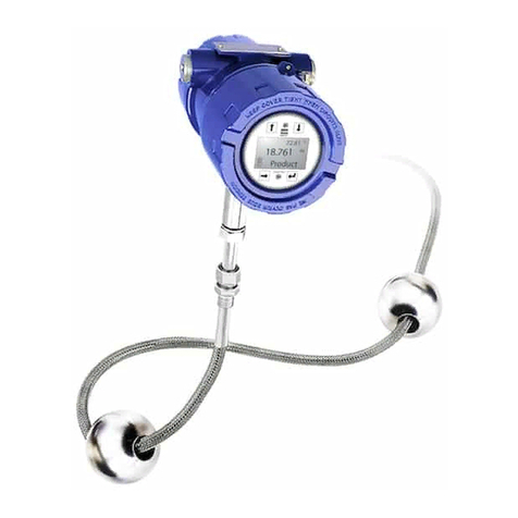
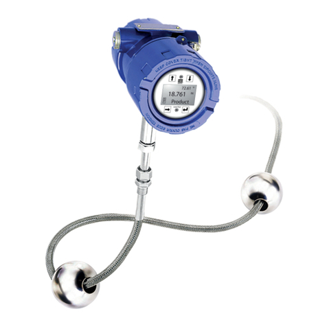
MTS Systems Level Plus Specification sheet

Magnetostrictive Liquid-Level Transmitters
with Temposonics®Technology
Level Plus®
OPERATION AND INSTALLATION MANUAL
M-Series Model MR Analog Transmitter
The Measurable Difference


Contact
Information
Model MR Operation and Installation Manual
Contact Information
MTS Sensors
Level Plus®Liquid-Level Transmitters M-Series Model MR Analog Transmitter
Operation and Installation Manual, Document Number: 550720 Revision K (EN) 02/2016
GERMANY
GENERAL:
Tel.:+49-2351-9587-0
Fax:+49-2351-56491
e-mail: [email protected]
http://www.mtssensors.com
MAILING AND SHIPPING ADDRESS:
MTS Sensor Technologie, GmbH & Co. KG
Auf dem Schüffel 9
D - 58513 Lüdenscheid, Germany
TECHNICAL SUPPORT AND APPLICATIONS:
Tel.:+49-2351-9587-0
e-mail: [email protected]
http://www.mtssensors.com
JAPAN
GENERAL:
Tel.: +81-42-775-3838
Fax: +81-42-775-5516
e-mail: [email protected]
http://www.mtssensors.com
MAILING AND SHIPPING ADDRESS:
MTS Sensors Technology Corporation
737 Aihara-cho, Machida-shi
Tokyo 194-0211, Japan
TECHNICAL SUPPORT AND APPLICATIONS:
Tel.: +81-42-775-3838
Fax: +81-42-775-5512
GENERAL:
Tel: +1-919-677-0100
Fax: +1-919-677-2343
E-mail: [email protected]
http://www.mtssensors.com
MAILING AND SHIPPING ADDRESS:
MTS Systems Corporation
Sensors Division
3001 Sheldon Drive
Cary, North Carolina, 27513, USA
CUSTOMER SERVICE:
Tel: +1-800-457-6620
Fax: +1-800-498-4442
E-mail: [email protected]
TECHNICAL SUPPORT AND APPLICATIONS:
24 Hour Emergency Technical Support
Tel: +1-800-633-7609
UNITED STATES
OFFICE HOURS (EST):
Monday - Thursday: 8:00 a.m. to 5:00 p.m.
Friday: 8:00 a.m. to 4:00 p.m.
REMITTANCE ADDRESS:
MTS Systems Corporation
Sensors Division
NW 5872
P.O. Box 1450
Minneapolis, MN, 55486-5872
QUOTE AND CONTRACT TERMS & CONDITIONS:
The parties expressly agree that the purchase and use of Material and/
or Services from MTS Sensors Division are subject to MTS’ Terms
and Conditions, in effect as of the date of this document, which
are located at http://www.mtssensors.com/leadmin/media/pdfs/
Terms_and_Conditions.pdf and are incorporated by reference into
this and any ensuing contract. Printed Terms and Conditions can
if you prefer, go to http://www.mtssensors.com/index and click the
Quote/Contract Terms and Conditions link at the bottom of the page
to download the PDF.
i

Reference
Information
MTS Sensors
Level Plus®Liquid-Level Transmitters M-Series Model MR Analog Transmitter
Operation and Installation Manual, Document Number: 550720 Revision K (EN) 02/2016
Model MR Operation and Installation Manual
Reference Information
Notices used in this manual
This manual contains notices to highlight specific information as follows:
Notes:
These notices provide important tips, guidance, or advice.
Important:
These notices provide information that might help you avoid inconvenient or problem situations.
Attention:
These notices indicate possible damage to programs, devices, or data and is placed just
before the instruction or situation in which damage could occur.
Caution:
These notices indicate situations that can be potentially hazardous to you. A Caution notice is placed just
before a description of a potentially hazardous procedure, step, or situation.
Related publications
The following publications are listed below by part number followed by description and are avail-
able in Adobe Acrobat Portable Document Format (PDF) at http://www.mtssensors.com/
550677 - Product Specification, Model MR Analog Transmitter
551103 - Level Plus Accessories Catalog
550731 - Component Replacement Guide
550904 - Application Datasheet Rigid
550905 - Application Datasheet Sanitary
550906 - Application Datasheet 7/8” Flex
551409 - Brief Operation Manual for Safe Use
550791 (PT) - Operation and Installation Manual, Model MG in Portuguese
550791 (KOR) - Operation and Installation Manual, Model MG in Korean
For information about safe work procedures, refer to the following documentation:
National Electric Code ANSI/NFPA 70
CSA C22.1 Canadian Electrical Code
How this manual is organized
“Introduction”, provides an overview of the manual.
“Terms and Definitions”, provides definitions of terms used in this manual.
“Product Overview”, gives an overall product description for the Level Plus liquid-level transmitter, its specifications, use, output,
and electronics.
“Installation and Mounting”, provides detailed installation and mounting information.
“Electrical Connections and Wiring Procedures”, provides engineering specifications and wiring diagrams to assist in the
installation process.
“Maintenance and Field Service”, provides guidelines for general float maintenance and procedures required for replacing the
Model MR electronic module or level transmitter.
“Troubleshooting”, provides a list of symptoms, their possible cause and the action to be taken when troubleshooting the
transmitter.
Setup using keypad display - describes modes of operation, LCD display functionality, alarm settings and how to calibrate the unit manually.
Setup using HART®Field Communicator - provides procedures for setting 4 and 20 mA set points
Setup using MTS Field Setup Software - provides software installation, parameter setup, and calibration procedures.
“Agency Information” provides comprehensive listings of agency approvals and standards, installation drawings, labels and applicable proto-
cols.
Getting information, help, and service
You can get the latest ordering information and software updates by visiting www.mtssensors.com website
General contact information, shipping and office hours are available on page i.
ii

Table of
Contents
MTS Sensors
Level Plus®Liquid-Level Transmitters M-Series Model MR Analog Transmitter
Operation and Installation Manual, Document Number: 550720 Revision K (EN) 02/2016
Model MR Operation and Installation Manual
Table of Contents
Contact information
General ........................................................................................i
Mailing and shipping address .....................................................i
Customer service ........................................................................i
Technical support and applications .............................................i
Office hours ................................................................................i
Remittance address ....................................................................i
Quote and contract terms and conditions ....................................i
Reference information
Notices used in this manual........................................................ ii
Related publications.................................................................... ii
How this manual is organized .....................................................ii
Getting information, help, and service ........................................ii
Introduction
Introduction............................................................... 1
Public website support portal ......................................... 1
Terms and Definitions
Terms and definitions reference ...................................... 2
Model MR product overview
Product overview ........................................................ 3
Industries....................................................................................3
Applications ................................................................................3
Features ......................................................................................3
Components .............................................................. 3
Housings.....................................................................................3
Outer pipe configurations ........................................................... 4
Floats .........................................................................................5
Internal electronics......................................................................5
Accessories ................................................................................5
Theory of operation...................................................... 6
Accuracy ................................................................. 6
Warranty ................................................................. 6
Model number identification........................................... 7
FM/CSA ......................................................................................7
ATEX/IECEx................................................................................. 8
Product specifications ................................................. 10
Model MR transmitter installation and mounting
Installation and mounting ............................................ 11
Storage ................................................................. 11
Stilling wells and guide poles ....................................... 11
Installation............................................................... 11
Rigid probe ...............................................................................11
Flexible probe ...........................................................................12
Mounting ................................................................ 13
Threaded flange mounting......................................................... 13
Welded flange mounting .......................................................... 13
Sanitary Tri-Clamp mounting ................................................... 14
Electrical connections and wiring procedures
Electrical connections and wiring procedures ..................... 15
Safety recommendations for installation ........................... 15
Recommended cable types ........................................... 16
Cable specifications .................................................................16
Electrical conduit installation ....................................... 16
Grounding ............................................................... 17
Safety barriers for IS installation .................................... 17
Maintenance and field service
Maintenance and field service ....................................... 18
General maintenance and field service requirements ........... 18
Float maintenance .................................................................... 18
Field service ............................................................................. 18
Service / RMA policy ................................................................18
Troubleshooting
Troubleshooting procedures ......................................... 18
Setup
Quick start-up guide.................................................... 19
Before you begin ...................................................................... 19
Quick start-up procedure ......................................................... 19
Setup using keypad display .......................................... 19
Operation modes ...................................................................... 19
LCD display and keypad (optional) ........................................... 20
Alarm settings ......................................................................... 20
Manual calibration ................................................................... 20
Setup using HART field communicator ............................. 22
Preparing the transmitter for re-calibration .............................. 22
Setting the low value ............................................................... 22
Setting the upper range value ................................................. 22
Setup using MTS Field Setup software ............................. 23
Using the MTS Field Setup software ........................................23
Advanced setup tab ................................................................. 24
Calibration tab ......................................................................... 25
Output tab ............................................................................... 25
Agency Information
Agency approvals ...................................................... 26
Hazardous area installation .......................................... 28
CSA ......................................................................................28
Installation drawings ............................................................ 28
Notes ................................................................................... 30
Wiring and connections ....................................................... 31
FM ......................................................................................34
Installation drawings ............................................................ 34
Notes ................................................................................... 36
Wiring and connections ....................................................... 37
ATEX and IECEx .......................................................................40
Installation Drawing .............................................................. 40
Notes ....................................................................................43
Wiring and Connection ......................................................... 44
Special Conditions for Use .................................................... 46
iii
Agency certifications .................................................. 47
ATEX .........................................................................................47
CSA.... ...................................................................................... 58
EC DECLARATION OF CONFORMITY ....................................... 60
FM ........................................................................................... 62
IECEx ....................................................................................... 66
NEPSI....................................................................................... 69
CCoE ........................................................................................ 77

MTS Sensors
Level Plus®Liquid-Level Transmitters M-Series Model MR Analog Transmitter
Operation and Installation Manual, Document Number: 550720 Revision K (EN) 02/2016 iv

MTS Sensors
Level Plus®Liquid-Level Transmitters - M-Series Model MR Analog Transmitter
Operation and Installation Manual, Part No.: 550720 Revision K (EN) 02/2016
Introduction
MTS is recognized as the pioneer, innovator and leader in magnetostrictive sensing. The new Level Plus®M-Series transmitter design repre-
sents a continuation of our on-going effort to provide effective, innovative and reliable products to the Liquid Level marketplace.
This manual will provide the following information about the Level Plus Model MR analog transmitter:
• Terms and definitions
• Product overview
• Installation and mounting
• Electrical connections and wiring procedures
• Maintenance and field service
• Troubleshooting
• Quick start-up guide
• Setup using the keypad display
• Setup using a HART®Field Communicator
• Setup using MTS Field Setup Software
• Agency information
• Product certifications
Public website support portal
Visit our support portal at http://www.mtssensors.com for:
• Building Level Plus M-Series Model MR analog transmitter model numbers
• Latest documentation releases
• Detailed ordering information
• Latest software updates
Model MR Operation and Installation Manual
Introduction
Introduction
1

MTS Sensors
Level Plus®Liquid-Level Transmitters - M-Series Model MR Analog Transmitter
Operation and Installation Manual, Part No.: 550720 Revision K (EN) 02/2016 2
Terms and definitions reference
E
Explosion-proof – Type of protection based on enclosure in which
the parts which can ignite an explosive gas atmosphere are placed
within, and which can withstand the pressure developed during an
internal explosion of an explosive mixture, and which prevents the
transmission of the explosion to the explosive gas atmosphere sur-
rounding the enclosure.
F
Flameproof – Type of protection based on enclosure in which the
parts which can ignite an explosive gas atmosphere are placed
within, and which can withstand the pressure developed during an
internal explosion of an explosive mixture, and which prevents the
transmission of the explosion to the explosive gas atmosphere sur-
rounding the enclosure.
H
HART®– a Bidirectional communication protocol that provides data
access between intelligent field instruments and host systems.
Terms and
Definitions
Model MR Operation and Installation Manual
Terms and Definitions
I
Interface – Noun; The measurement of the level of one liquid when
that liquid is below another liquid.
Interface – Adj.; The Software Graphical User Interface (GUI) that
allows the user to access software protocols (HART).
Intrinsic safety – ‘Intrinsically safe’ - Type of protection based on the
restriction of electrical energy within apparatus of interconnecting
wiring exposed to potentially explosive atmosphere to a level below
that which can cause ignition by either sparking or heating effects.
N
NEMA Type 4X – A product Enclosure intended for indoor or outdoor
use primarily to provide a degree of protection against corrosion,
windblown dust and rain, splashing water, and hose-directed water;
and to be undamaged by the formation of ice on the enclosure. They
are not intended to provide protection against conditions such as
internal condensation or internal icing.
NPT – U.S. standard defining tapered pipe threads used to join pipes
and fittings.
S
Specic Gravity – The density ratio of a liquid to the density of water
at the same conditions.

MTS Sensors
Level Plus®Liquid-Level Transmitters - M-Series Model MR Analog Transmitter
Operation and Installation Manual, Part No.: 550720 Revision K (EN) 02/20163
Model MR product overview
The Level Plus Model MR Liquid-Level transmitter is a continuous multi-functional magnetostrictive transmitter that provides product level,
interface level, and temperature to the user via 4 to 20 mA current loops or HART. Magnetostrictive technology is one of the most accurate
and repeatable level technologies available to date. MTS is the inventor and purveyor of magnetostrictive technology and has been serving the
level industry for over 30 years.
INDUSTRIES APPLICATIONS FEATURES
Petroleum
Liquid petroleum gas
Pharmaceutical
Food & beverage
Chemical
Wastewater
Mining
Tank farms
Terminals
Bullet tanks
Separator tanks
Battery tanks
Storage tanks
Solvent extraction
3-in-1 measurement
- Product level
- Interface level
- Temperature
No scheduled maintenance or recalibration
Field repairable
AMS Aware
Components
The Level Plus Model MR liquid level transmitter consists of four main components; a housing, outer pipe, float, and electronics. Varying the
components of the transmitter allows the transmitter to be customized to almost any application.
HOUSINGS
Level Plus Model MR transmitters are available in three housing configurations; NEMA Type 4X 316L stainless steel, explosion-proof single
and dual-cavity housings as shown below:
NEMA Type 4X 316L stainless-steel housing
Top View
123 mm
(4.85 in.) O.D.
81 mm
(3.19 in.)
152 mm
(6 in.) ½ in. NPT conduit access
Single cavity explosion-proof housing
127 mm
(5 in.)
210 mm
(8.25 in.)
123 mm
(4.84 in.)
81 mm
(3.18 in)
Optional
display 3/4 in. NPT
conduit access
M20x1.5 (ATEX)
121 mm
(4.75 in.)
O.D.
Dual cavity explosion-proof housing
127 mm
(5 in.)
210 mm
(8.25 in.)
127 mm
(5 in.)
210 mm
(8.25 in)
176 mm
(6.95 in.)
81 mm
(3.47 in)
Optional
display 3/4 in. NPT
conduit access
M20x1.5 (ATEX)
121 mm
(4.75 in.)
O.D.
Model MR Operation and Installation Manual
Product Overview, Components
Product
Overview

MTS Sensors
Level Plus®Liquid-Level Transmitters - M-Series Model MR Analog Transmitter
Operation and Installation Manual, Part No.: 550720 Revision K (EN) 02/2016
Model MR Operation and Installation Manual
Product Overview, Components
4
OUTER PIPE CONFIGURATIONS
The outer pipe is constructed of a variety of configurations, shown below. Contact factory for other materials (such as Hastelloy C or Teflon).
74 mm (2.9 in.) min.
Inactive zone
3/4 in. NPT
Adjustable fitting
Tip of transmitter
Tank flange
(provided by customer)
Order length
95 mm (3.75 in.)
minimum
Pipe diameter
16 mm (0.625 in.)
Figure 1. 5/8 in. diameter rigid outer pipe of 316L stainless steel
Sanitary process connnection
(sanitary cap)
Pipe diameter 16 mm (0.625 in. dia.)
constructed of 316L stainless steel
Order length
49 mm
(1.9 in.) Typical
Figure 2. 5/8 in. diameter rigid outer pipe of polished 316L
stainless steel with sanitary process connection and end plug
Order length
Outer flex pipe 7/8” dia.
(316L stainless steel)
305 mm (12 in.)
686 mm (27.0 in.)
Tank
flange
1 in. NPT Adjustable
compression fitting, male
Bottom-fixing
Magnet
Bottom-fixing WeightBottom-fixing Hook
76.2 mm
(3.0 in.) 127 mm
(5.0 in.)
50.8 mm
(2.0 in.) Typ.
Figure 3. 7/8 in. diameter flexible pipe of 316L stainless steel
Product
Overview

MTS Sensors
Level Plus®Liquid-Level Transmitters - M-Series Model MR Analog Transmitter
Operation and Installation Manual, Part No.: 550720 Revision K (EN) 02/20165
FLOATS
Model MR transmitters offer numerous floats for different applications such as stainless steel, 3-A sanitary, hastelloy, Teflon, and Nitrophyl
for both product level and interface level. To be able to accurately detect the interface level there needs to be a difference of at least 0.05 in
specific gravities between the product and interface liquids. For detailed information about floats, refer to the ‘Accessories Catalog’, MTS part
number 551103.
For assistance with selecting a specific float for your application, please contact Technical Support with the following information:
• Specific gravity of liquid(s) being measured
• Process temperature • Process Opening Size
• Vessel pressure
For ATEX, IECEx, and CCoE approvals, Model MR transmitters should be used with a float having an offset weight and made of stainless steel
or Hastelloy C. This allows the float to stay in contact with the pipe to prevent the buildup of an electrostatic charge. For detailed information
about floats, refer to the ‘Accessories Catalog’, MTS part number 551103.
Non-metalic floats with a projected surface area of less than 5,000 mm² should only be used in Zone 0, Gas group IIA such as float part
numbers 201643-2, 201649-2, 201650-2, 201109, 251115 and 251116. All other non-metallic floats offered by MTS such as, 251939,
251119, 251120 and 252999, should not be used in a hazardous area application.
NITROPHYL FLOATS
Float and dimension reference
Projected
surface
area
Part number
18 mm
(.07 in.) dia.
Magnet
C
L
76 mm
(3 in.)
31 mm
(1.2 in.) dia.
Added weight
for interface floats
2356 mm²
201643-2
201649-2
201650-2
TEFLON FLOATS
Float and dimension reference
Projected
surface
area
Part number
4635 mm²
201109
251115
251116
INTERNAL ELECTRONICS
All transmitters come with two electronic components of a sensing element and a board set. All sensing elements up to 300 inches (7620
mm) are rigid and greater lengths have flexible sensing elements. Flexible sensing elements are only available under 300 inches (7620 mm)
as special orders. The board set consists of a electronic puck and interconnect board. The board set can be configured for single or dual loop
output offering the ability to output the product level, interface level, and temperature. All three variables can be communicated via HART.
The electronic puck can be ordered with or without a display. The optional display is capable of displaying the product level, interface level, and
temperature. Designed into the optional display are three push buttons for local setup of 4 and 20 mA set points.
A temperature sensing function is optional with the Model MR transmitter. The temperature sensing device is a Resistive Temperature Device
(RTD) mounted inside the transmitter’s outer pipe assembly. The RTD is a 1000 ohm platinum film device.
ACCESSORIES
MTS also offers a series of displays, housings, converters, and other accessories, please refer to the ‘Accessories Catalog’, MTS part number
551103.
Model MR Operation and Installation Manual
Product Overview, Components
Product
Overview
61 mm
(2.38 in.) dia.
76 mm
(3 in.)
9 mm
(0.35 in.)
Magnet
Centerline
of Magnet
18 mm
(0.7 in.) dia.

MTS Sensors
Level Plus®Liquid-Level Transmitters - M-Series Model MR Analog Transmitter
Operation and Installation Manual, Part No.: 550720 Revision K (EN) 02/2016
Theory of operation
Magnetostrictive M-Series transmitters precisely sense the posi-
tion of an external float by applying an interrogation pulse to a
waveguide medium. This current pulse causes a magnetic field
to instantly surround the waveguide. The magnet installed within
the float also creates a magnetic field. Where the magnetic fields
from the waveguide and float intersect, a rotational force is created
(waveguide twist). This, in turn, creates a torsional-sonic pulse that
travels along the waveguide as shown in Figure 4.
The head of the transmitter houses the sensing circuit, which de-
tects the torsional-sonic pulse and converts it to an electrical pulse.
The distance from a reference point to the float is determined by
measuring the time interval between the initiating current pulse and
the return pulse and precisely knowing the speed of these pulses.
The time interval is converted into a level measurement.
Figure 4. Theory of operation
Accuracy
For magnetostrictive transmitters inherent accuracy is measured in terms of non-linearity. Non-linearity is a measurement of any imperfec-
tions in the waveguide that are reflected in the linearity of the transmitter’s output. MTS tolerances reflect a maximum non-linearity of 0.02%
of full scale. MTS is able to achieve such strict tolerances by manufacturing all of its own waveguide from a proprietary alloy and testing 100%
of all transmitters before shipping.
Warranty
6
All M-Series transmitters come with a two year limited warranty from
the factory shipment date. A Return Materials Authorization (RMA)
number is required and must accompany any transmitter returns.
Any unit that was used in a process must be properly cleaned in
accordance with OSHA standards, before it is returned to the factory.
A Material Safety Data Sheet (MSDS) must also accompany the
transmitter that was used in any process.
Important:
Contact Technical Support or Customer Service for assistance if you
suspect that the transmitter is not working correctly. Technical support
can assist you with troubleshooting, part replacement, and Returned
Material Authorization (RMA) information if required.
Model MR Operation and Installation Manual
Theory of Operation, Accuracy, and Warranty
Product
Overview

MTS Sensors
Level Plus®Liquid-Level Transmitters - M-Series Model MR Analog Transmitter
Operation and Installation Manual, Part No.: 550720 Revision I (EN) 06/2014
Product
Overview
7
Model number identification for FM and CSA approvals
TRANSMITTER MODEL =M1
M= Magnetostrictive transmitter
TYPE =R2
R= Analog output liquid-level transmitter
AGENCY APPROVAL =3
F= FM C= CSA
3= 3-A
OUTPUT =4
1= 4-20 mA Single loop with HART 2= 4-20 mA Dual loops with HART
HOUSING TYPE =5
A= NEMA Type 4X, 316L stainless steel with cable (intrinsically
safe only) E= Dual cavity with display (explosion-proof and intrinsically
safe)
B= Single cavity (explosion-proof and intrinsically safe) L= NEMA Type 4X, 316L SS w/6-pin male connector
(intrinsically safe only)
C= Dual cavity (explosion-proof and intrinsically safe) 3= NEMA Type 4X, 316L SS with internal terminal blocks
(intrinsically safe only)
D= Single cavity with display (explosion-proof and intrinsically safe)
ELECTRONICS MOUNTING =6
1= Integral electronics
TRANSMITTER PIPE =7
B= Industrial end-plug with stop collar F= Sanitary, drain-in-place, no hole, DN
C= Sanitary, T-bar, TB H= Flexible w/bottom fixing hook (stainless steel only)
D= Sanitary, drain-in-place, DP J= Flexible w/bottom fixing weight (stainless steel only)
E= Sanitary, clean-in-place, CP K= Flexible w/bottom fixing magnet (stainless steel only)
MATERIALS OF CONSTRUCTION (WETTED PARTS) =8
Note: contact factory for other materials
1= 316L stainless steel A= Teflon
2= Electropolished 316L stainless steel Ra 15 C= CRN Approved
3= Hastelloy C
PROCESS CONNECTION TYPE =9
1= NPT adjustable fitting 6= 150 lb. welded RF flange
4= Sanitary, welded 7= 300 lb. welded RF flange
5= Sanitary, adjustable 8= 600 lb. welded RF flange
PROCESS CONNECTION SIZE =10
A= ¾ in. (NPT for 5/8in. pipe) F= 3 in.
B= 1 in. (NPT for 7/8in. hose) G= 4 in.
C= 1½ in. H= 5 in. (except sanitary)
D= 2 in. J= 6 in.
E= 2½ in.
TEMPERATURE =11
0= None 2= One RTD, customer defined position∆
Note: ∆ (if this option is selected, position ‘18 E’ must
also be selected)
1= One RTD, fixed position 76 mm (3 in.) from the end of pipe
UNIT OF MEASUREMENT =12
M= Metric (millimeters) Encode length in millimeters if using metric
(XXXXX mm) U= US Customary (inches) Encode length in inches if
ordering in US Customary (XXX.XX in.)
LENGTH =13-17
= Order length based on unit of measurement = Teflon 508 mm (20 in.) to 6096 mm (240 in.)
= Flexible transmitter: 3048 mm (120 in.) to 12,192 mm (480 in.)
(FM IS Group D only) = Rigid/Sanitary transmitter: 508 mm (20 in.) to
7620 mm (300 in.)
SPECIAL =18
S= Standard product E= Engineering special
(not affecting agency controlled parts or features)
Model MR Operation and Installation Manual
Model Number Identification - FM and CSA

MTS Sensors
Level Plus®Liquid-Level Transmitters - M-Series Model MR Analog Transmitter
Operation and Installation Manual, Part No.: 550720 Revision K (EN) 02/2016 8
Model number identification for ATEX and IECEx based approval
TRANSMITTER MODEL =M1
M= Magnetostrictive transmitter
TYPE =R2
R= Analog output level transmitter
APPROVAL AGENCY =3
E= ATEX Approved
H= IECEx Approved
OUTPUT =4
1= 4-20 mA Single loop with HART 2= 4-20 mA Dual loops with HART
HOUSING TYPE =5
B= SIngle cavity (Flameproof IIB) J= Single cavity with display (ATEX, Ex ia IIA)
C= Dual cavity (Flameproof IIB) K= Dual cavity with display (ATEX, Ex ia IIA)
D= Single cavity with display (Flameproof IIB) P= NEMA Type 4X, 316L stainless steel with cable (ATEX, Ex ia IIB)
E= Dual cavity with display (Flameproof IIB) R= Single cavity (ATEX, Ex ia IIB)
F= NEMA Type 4X, 316L stainless steel with cable (ATEX, Ex ia IIA) S= Dual cavity (ATEX, Ex ia IIB)
G= Single cavity (ATEX, Ex ia IIA) T= Single cavity with display (ATEX, Ex ia IIB)
H= Dual cavity (ATEX, Ex ia IIA) U= Dual cavity with display (ATEX, Ex ia IIB)
ELECTRONICS MOUNTING =6
1= Integral electronics
TRANSMITTER PIPE/HOSE =7
B= Industrial end-plug with stop collar H= Flexible w/bottom fixing hook (stainless steel only)
C= Sanitary, T-bar, TB J= Flexible w/bottom fixing weight (stainless steel only)
D= Sanitary, drain-in-place, DP K= Flexible w/bottom fixing magnet (stainless steel only)
E= Sanitary, clean-in-place, CP L= Sanitary Special
F= Sanitary, drain-in-place, no hole, DN
MATERIALS OF CONSTRUCTION (WETTED PARTS) (Note: contact factory for other materials) = 8
1= Stainless steel, 1.4404 A= Teflon / FEP
2= Stainless steel, 1.4404 electropolished
3= Hastelloy C
PROCESS CONNECTION TYPE =9
1= NPT, Adjustable fitting 7= 300 lbs. Welded RF flange
4= Sanitary, welded 8= 600 lbs. welded RF flange
5= Sanitary, adjustable fitting 9= DIN flange welded according to specification
6= 150 lbs. welded RF flange
PROCESS CONNECTION SIZE =10
A= ¾ in. (NPT for 5∕8in. pipe) F= 3 in.
B= 1 in. (NPT for 7∕8in. hose) G= 4 in.
C= 1½ in. H= 5 in. (except sanitary)
D= 2 in. J= 6 in.
E= 2½ in.
TEMPERATURE =11
0= None 1= One RTD, fixed position 76 mm (3 in.) from the end of pipe
2= One RTD, customer defined position łł
Note: łłIf this RTD option is selected, option ‘18 E ’ must also be selected
UNIT OF MEASUREMENT =12
M= Metric (millimeters) Encode length in millimeters if using metric
(XXXXX mm) U= US Customary (inches) Encode length in inches if ordering
in US Customary (XXX.XX in.)
Model MR Operation and Installation Manual
Model Number Identification - ATEX and IECEx
Product
Overview
P=CCoE approved
K=KC approved
B= INMETRO approved

MTS Sensors
Level Plus®Liquid-Level Transmitters - M-Series Model MR Analog Transmitter
Operation and Installation Manual, Part No.: 550720 Revision K (EN) 02/2016
Model MR Operation and Installation Manual
Model Number Identification - ATEX and IECEx
Product
Overview
9
Model number identification for ATEX and IECEx based approval
LENGTH (Order length based on unit of measurement) = 13-17
=Rigid or Sanitary transmitter: 508 mm (20 in.) to 7620 mm (300 in.) = Teflon: 508 mm (20 in.) to 6096 mm (240 in.)
= Flexible transmitter: 3048 mm (120 in.) to 12,192 mm (480 in.) except ATEX, Ex ia IIB max. length 7620 mm (300 in.)
SPECIAL =18
S= Standard product E= Engineering special (not affecting agency controlled parts or features)

MTS Sensors
Level Plus®Liquid-Level Transmitters - M-Series Model MR Analog Transmitter
Operation and Installation Manual, Part No.: 550720 Revision K (EN) 02/2016 10
Model MR Operation and Installation Manual
Product Specifications
Parameters Specifications
LEVEL OUTPUT
Measured
variable: Product level and interface level
Output signal /
Protocol: 4 to 20 mA with HART®, 1 or 2 loop
Order length: Flexible hose:
(ATEX Ex ia IIB, FM IS Group C, D):
3048 mm (120 in.) to 7620 mm (300 in.) ∆§
(All else):**
3048 mm (120 in.) to 12200 mm (480 in.) ∆§
*FM I.S. Group D only
Rigid pipe:
508 mm (20 in.) to 7620 mm (300 in.) ∆ §
Sanitary pipe:
508 mm (20 in.) to
7620 mm (300 in.) ∆ §
∆Contact factory for longer lengths.
§ Order length equals the measurement range plus
the inactive zone.
Non-linearity: 0.02% F.S. or 0.794 mm (1/32 in.)*
*Whichever is greater
Repeatability: 0.01% F.S. or 0.381 mm (0.015 in.)*
(any direction)
†Contact factory for alternative materials.
TEMPERATURE OUTPUT
Measured
variable: Single-point temperatures
Type: 4 to 20 mA from 1000Ω platinum RTD
at 0 °C
Repeatability: ±0.1 °C (±0.18 °F)
Temperature
accuracy: ±1.5 °C (±2.7 °F)
Drift: ±0.5 ºC (±0.9 ºF) per year
ELECTRONICS
Input voltage: 10.5 to 36 Vdc, 28 Vdc maximum for I.S.
approval
Fail safe: High (21.4 mA), or Low (3.8 mA)
Reverse polarity
protection: Series diode
Lightning/
Transient
protection:
Stage 1:
Line-to-ground surge suppression;
IEC 61000-4-5
Stage 2:
Line-to-line and line-to-ground transient
suppressors; IEC 61000-4-4
CALIBRATION
Zero adjust
range: Anywhere within the active length
Span adjust
range: Full scale to 152 mm (6 in.) from zero
Parameters Specifications
ENVIRONMENTAL
Enclosure rating: NEMA Type 4X
Humidity: 0 to 100% relative humidity,
non-condensing
Operating
temperatures:
Electronics*:
-40 °C (-40 °F) to 71 °C (160 ºF)
Sensing element:
-40 °C (-40 °F) to 125 °C (257 °F) ◊
Temperature element:
-40 °C (-40 °F) to 105 °C (221 °F)
◊Contact factory for specific temperature ranges.
* Consult Agency Approvals section for approved
specific ambient temperature rating
Vessel pressure: Industrial rigid pipe: 1000 psi (70 bar)
Sanitary pipe: 435 psi (30 bar)
Teflon pipe: 100 psi (7 bar)
Flexible Hose: 260 psi (18 bar)
Materials: Wetted parts: 316L stainless steel †
Non-wetted parts: 316L stainless steel,
Epoxy coated aluminum
†Contact factory for alternative materials.
FIELD INSTALLATION
Housing
dimensions: Single cavity:
127 mm (5 in.) by 133 mm (5.25 in.)
123 mm (4.84 in.) O.D.
Dual cavity:
127 mm (5 in.) by 177 mm (6.95 in.)
123 mm (4.84 in.) O.D.
NEMA Type 4X:
81 mm (3.2 in.) by 123 mm (4.85 in.) O.D.
MOUNTING
Rigid pipe: ¾ in. Adjustable MNPT fitting
Flange or Tri-Clamp®Mount
Flexible hose: 1 in. Adjustable MNPT fitting
Flange mount
WIRING
Connections: 2-wire shielded cable or twisted pair,
Daniel Woodhead 6-pin male connector,
4570 mm (180 in.) integral cable with
pigtail
ELECTRICAL CONNECTIONS
Single and Dual
Cavity: ¾ in. FNPT conduit opening, M20 for
ATEX/IECEx/CCoE version
NEMA Type 4X: ½ in. FNPT conduit opening
DISPLAY
Measured
variables:
Product level, interface level and
temperature
Size: 13 mm (0.5 in.)
Number of digits: 16
Model MR product specifications
Product
Overview

MTS Sensors
Level Plus®Liquid-Level Transmitters - M-Series Model MR Analog Transmitter
Operation and Installation Manual, Part No.: 550720 Revision K (EN) 02/201611
Installation and mounting
If the installation is going to occur in a hazardous area, completely read the Agency Information section before starting any work. The Agency
Information outlines additional regulations that need to be followed in order for the installation to comply with hazardous area regulations.
This section contains information about storing your transmitter (prior to installation) and detailed procedures for installing and mounting your
transmitter.
Storage
If storage is required prior to installation, store indoors in a dry environment at ambient temperature range not exceeding -40 °C (-40 °F) to
71 °C (160 °F).
Stilling wells and guide poles
Level Plus transmitters can be mounted in slotted or unslotted stilling wells but a slotted stilling well is always preferred. Using a unslotted
stilling well will negatively affect performance of any level device as the level in the stilling well can differ from the level in the tank. The Level
Plus transmitter can also be installed to one side of the stilling well to also allow for sampling and manual gauging from the same opening as
the automatic tank gauging. Contact Technical Support for details.
Level Plus transmitters do not require a stilling well for installation. Our transmitters are installed in numerous tanks without stilling wells with
no loss in performance due to our patented flexible waveguide and hose. A stilling well is highly recommended for agitated, turbulent, and/or
fast filling tanks.
Installation
The installation procedures below are illustrated using the adjustable NPT fitting for a threaded flange mount. The procedures will have to be
slightly adjusted if using a welded flange or sanitary Tri-Clamp mount.
RIGID PROBE
Tools Required:
• Channel lock pliers
• Common screwdriver
• 5/32 in. Hex key (allen wrench)
Caution:
It is recommended that assembly and mounting of this transmitter should not be performed alone. To ensure proper and safe assembly of the Level
Plus transmitter, a minimum of two (2) individuals are recommended. Gloves are also recommended. In addition , PPE is required for work areas such
as safety shoes, safety glasses, hard hat, and fire resistant clothing.
Perform the following steps to Install the RefineME transmitter:
1. Remove the stop collar and E-ring. With assistance, feed the rigid pipe through the hole of the removed tank flange until the flange is
positioned near the top of the transmitter. Insert the threaded portion of the adjustable fitting into the customer supplied flange and
tighten (apply pipe thread sealant if required). Be careful not to drop the flange as it can damage the transmitter.
2. Slide the product float onto the rigid pipe. Slide the interface float (optional) onto the rigid pipe. Install stop collar 2 inches from the
bottom (see ‘Note’ below). Do not drop the float(s) or allow them to free fall along the rigid pipe as damage may result.
Note:
The stop collar can be removed or adjusted based on the float selected for the application. Please consult the factory for more information.
3. Slide float(s) back down to the stop collar to prevent them from free falling during installation into the tank. Insert the rigid pipe
(with floats) through the tank opening and lower the transmitter/float assembly into the tank until it rests on the bottom. DO NOT
DROP OR DAMAGE THE PIPE.
4. Secure the flange onto the tank mount.
5. Pull the transmitter upward so the end plug is just resting on the floor of the tank. Tighten the adjustable fitting to hold the transmitter
in place.
6. Terminate the field wire cables noting proper wire orientation.
Model MR Operation and Installation Manual
Installation, Mounting and Storage
Installation &
Mounting

MTS Sensors
Level Plus®Liquid-Level Transmitters - M-Series Model MR Analog Transmitter
Operation and Installation Manual, Part No.: 550720 Revision K (EN) 02/2016 12
FLEXIBLE PROBE
Caution:
When assembling and installing the Model MR transmitter, be careful not to allow the flexible hose to kink or be coiled in less than 16 in. (406.5 mm)
diameter. It is recommended that assembly and mounting of this transmitter should not be done alone. To ensure proper and safe assembly of the
Model MR transmitter, a minimum of two (2) individuals are recommended. Gloves are also recommended. PPE is required for work areas such as safe-
ty shoes, safety glasses, hard hat, and fire resistant clothing.
Tools Required:
• 9/16 in. Socket and ratchet
• Channel lock pliers
• 3/16 in. Hex key (allen wrench)
1. Remove the stop collar. With assistance, feed the flexible hose through the hole of the removed tank flange until the flange is
positioned at the rigid section of pipe near the top of the transmitter. Insert the threaded portion of the adjustable fitting into the
customer supplied flange and tighten (apply pipe thread sealant if required). Be careful not to drop flange on the flexible hose as
damage may result.
2. Slide the product float onto the flexible pipe. Slide the interface float (optional) onto the flexible pipe. Install stop collar 3 inches from
the bottom of rigid section (see ‘Note’ below). Do not drop float(s) or allow them to free fall along the flexible pipe as damage may
result.
Note:
The stop collar can be removed or adjusted based on the float selected for the application. Please consult the factory for more information.
3. Mount the hook, weight, or the magnet to the welded end-plug section of the pipe (this is the bottom rigid section of the pipe) using the
supplied nut, spacer and washer, tighten securely as shown in Figure 5. For the magnet, remove washer before
installing in tank.
Weight
Flexible pipe
Magnet
Transmitter retention
using weight
Bottom-fixing hook
(mates with customer supplied
hardware mounted in the
tank bottom)
Nut
Welded
end-plug
Washer
Spacer
Flexible pipe
Welded
end-plug
Nut Washer
Spacer
Flexible pipe
Welded
end-plug
Transmitter retention
using magnet
Transmitter retention using
bottom-xing hook
Remove
washer
Figure 5. Bottom fixing hardware
DO NOT DROP OR DAMAGE THE PIPE
Important: Avoid kinking or bending the flexible pipe in less than 16 inch (406 mm) diameter or damage may result.
4. Slide float(s) back down to the stop collar to prevent them from free falling during installation into the tank. Insert the flex pipe and
floats through the tank riser pipe and lower the transmitter/float assembly into the tank until it rests on the bottom. If you are using
a bottom-fixing hook, fasten the hook to the appropriate customer-supplied mating hardware at the tank bottom.
5. Secure the flange onto the tank riser pipe.
6. Pull the transmitter upward to straighten the flexible pipe until the resistance of the weight, magnet, or hook is felt without raising the
weight or magnet off the floor of the tank. Tighten the adjustable fitting to hold the transmitter in place.
7. Terminate the field wire cables noting proper wire orientation.
Model MR Operation and Installation Manual
Installation, Mounting and Storage
Installation &
Mounting

MTS Sensors
Level Plus®Liquid-Level Transmitters - M-Series Model MR Analog Transmitter
Operation and Installation Manual, Part No.: 550720 Revision K (EN) 02/2016
Installation &
Mounting
13
Mounting
The method of mounting the transmitter is dependent on the vessel or tank in which it is being used, and what type of transmitter is being
mounted. There are three typical methods for mounting; threaded flange mounting, welded flange mounting, and sanitary Tri-Clamp mounting.
THREADED FLANGE MOUNTING
In most applications, the Model MR transmitter can be mounted
directly to the tank or flange via a NPT threaded fitting, assuming
there is a proper threaded connection available. If the float will not fit
through the flange opening when the flange is removed, there must
be some alternative means to mount the float on the transmitter from
inside the vessel; this may require an access port nearby the entry
point of the transmitter as shown in Figure 6.
Riser
NPT fitting
Tank flange
(customer supplied
or ordered separately)
Float access
port
Tip of transmitter
Figure 6. Threaded flange mounting for rigid and flexible pipe
WELDED FLANGE MOUNTING
The Model MR transmitter can also be mounted to a tank flange as
shown in Figure 7. First, install float(s) onto the transmitter. Second,
install the float retaining hardware on the tip of the transmitter. To
complete the installation, mount the transmitter, flange and float(s)
as a unit in to the tank.
Welded flange
Tank flange
Welding sleeve
28.6 mm
(1.13 in.) dia
Product float
Riser
Stainless-steel
flexible pipe
Interface float
Bottom-fixing weight,
magnet or hook
Figure 7. Welded flange mounting for rigid and flexible pipe
Model MR Operation and Installation Manual
Threaded and Welded Flange Mounting

MTS Sensors
Level Plus®Liquid-Level Transmitters - M-Series Model MR Analog Transmitter
Operation and Installation Manual, Part No.: 550720 Revision K (EN) 02/2016 14
SANITARY TRI-CLAMP MOUNTING
In sanitary applications, the Model MR transmitter is mounted to the tank using a standard sanitary connection and clamp as shown in
Figure 8. In most cases it is not necessary to remove the float as the sanitary end-plug fitting is sized to allow installation with the float in place.
Please note that some sanitary end-plug styles have float(s) permanently mounted as shown in Figure 9. To install the clamp, the transmitter
and float(s) into the mating process connection and attach the sanitary Tri-Clamp.
Mating process connection
(Customer supplied)
Top
view
Cable
(Customer supplied)
123 mm
(4.85 in.)
Riser
Sanitary float
(Permanently mounted on some
transmitter pipe styles)
81 mm
(3.19 in.)
152 mm
(6.0 in.)
Tip of transmitter
Sanitary clamp
(Customer supplied) Sanitary cap (welded to transmitter pipe)
Figure 8. M-Series Model MR transmitter. Tank mounted with sanitary connection
CP
Clean-in-place
DP
Drain-in-place
with end plug*
TB
Sanitary*
Inactive zone:
81 mm (3.2 in.)
from tip (typical)
*This end plug style has permanently mounted floats. Floats cannot be removed from pipe.
DN
Drain-in-place
no through hole
Inactive zone:
74 mm (2.9 in.)
from tip (typical)
Inactive zone:
74 mm (2.9 in.)
from tip (typical)
Inactive zone:
81 mm (3.2 in.)
from tip (typical)
Figure 9. End-plug options for transmitters in a sanitary pipe application
Model MR Operation and Installation Manual
Tri-Clamp Mounting
Installation &
Mounting
Other manuals for Level Plus
2
Table of contents
Other MTS Systems Transmitter manuals