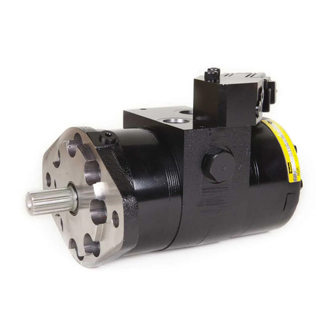
Parker 700 Series Manual

Bulletin SM1531-001/US
Pump/Motor Division
Effective: May 2006
700 Series
Low Speed
High Torque
Service Procedure

Bulletin 1531-001/USA Pump/Motor Division
700 Series Service Procedure
Parker Hannin Corporation
Hydraulic Pump/Motor Division
Greeneville, TN 37745 USA
2
FAILURE OR IMPROPER SELECTION OR IMPROPER USE OF THE PRODUCTS AND/OR SYSTEMS DESCRIBED HEREIN OR RELATED
ITEMS CAN CAUSE DEATH, PERSONAL INJURY AND PROPERTY DAMAGE.
This document and other information from Parker Hannin Corporation, its subsidiaries and authorized distributors provide product and/or
system options for further investigation by users having technical expertise. It is important that you analyze all aspects of your application
and review the information concerning the product or system in the current product catalog. Due to the variety of operating conditions and
applications for these products or systems, the user, through its own analysis and testing, is solely responsible for making the nal selection
of the products and systems and assuring that all performance, safety and warning requirements of the application are met.
The products described herein, including without limitation, product features, specications, designs, availability and pricing, are subject to
change by Parker Hannin Corporation and its subsidiaries at any time without notice.
WARNING
The items described in this document are hereby offered for sale by Parker Hannin Corporation, its subsidiaries or its authorized distributors.
This offer and its acceptance are governed by the provisions stated in the "Offer of Sale".
Copyright 2006, Parker Hannin Corporation, All Rights Reserved
Offer of Sale

Bulletin 1531-001/USA Pump/Motor Division
700 Series Service Procedure
Parker Hannin Corporation
Hydraulic Pump/Motor Division
Greeneville, TN 37745 USA
3
Table of Contents
Contents
Introduction ................................................................................................................. 4
Troubleshooting Guide ............................................................................................. 5-6
Tools & Materials Required for Maintenance .............................................................. 7
Service Parts List ................................................................................................... 8-10
Exploded Views .................................................................................................... 11-13
Disassembly & Inspection .................................................................................... 14-15
Assembly .............................................................................................................. 16-17
Final Checks ............................................................................................................. 18
Maintenance Tips ...................................................................................................... 19
Offer of Sale .............................................................................................................. 20

Bulletin 1531-001/USA Pump/Motor Division
700 Series Service Procedure
Parker Hannin Corporation
Hydraulic Pump/Motor Division
Greeneville, TN 37745 USA
4
Introduction
The 700 series Low Speed High Torque (LSHT) hydraulic motor is designed to provide
long life while operating with low radial side loads. Refer to catalog radial load limits. However, should
maintenance be required, the instructions below should be used for disassembly, replacement of parts,
cleaning and assembly.
Read the trouble shooting information to eliminate non-hydraulic causes and hydraulic system problems. The
check list identies hydraulic system and possible motor component problems. Read all disassembly and
assembly sections carefully. Pay special attention to the notes, cautions and warnings.
The component part names and item numbers assigned on the exploded assembly views corresponds with
names and item numbers (in parentheses) used in the disassembly and assembly procedures. Refer to the
exploded assembly view page as you follow the procedures for ease in identifying and locating components.
Service part number charts display exploded view item numbers and part numbers.
Obtain service parts from the Original Equipment Manufacturer or your local Parker Distributor.
We welcome suggestions to make this manual clearer or more complete. If you are stuck, please contact our
customer service department. Don't second guess the manual. Following this safe and productive procedure
results in restoring the reliable, long-life operation engineered into the motor.
Important Notes:
Prior to any motor disassembly, plug the open ports and case drain. Clean all dirt from the outside of
the motor.
Prior to assembly lightly oil all seals, the rollers and the threaded bolt ends.

Bulletin 1531-001/USA Pump/Motor Division
700 Series Service Procedure
Parker Hannin Corporation
Hydraulic Pump/Motor Division
Greeneville, TN 37745 USA
5
Preliminary Checks
Hydraulic systems are often trouble-free. Hence, the
problem an operator complains of could be caused by
something other than the hydraulic components.
Thus, once you have determined that a problem ex-
ists, start with the easy-to-check items, such as:
• Parts damaged from impact that were not
properly repaired, or that should have been
replaced
• Improper replacement parts used in previous
servicing
• Mechanical linkage problems such as bind-
ing, broken or loose parts, or slipping belts
Hydraulic Components
If the motor has low speed or torque, look at the check
list on the next page rst. Since these motors maintain
volumetric and torque efciencies during their usual
life, the problem is usually elsewhere in the hydraulic
system.
However, there are hydraulic system problems which
can drastically reduce the long life designed into these
motors. Three key areas to check are:
• Temperature: Do not exceed 180˚F.
• Fluid: Viscosity at the maximum temperature
must exceed 50 ssu.
• Filtration: A Beta 25 ratio of at least 2.
Troubleshooting Guide
Preparation
Make your troubleshooting easier by preparing as fol-
lows:
• work in a clean, well-lighted place
• have proper tools and materials nearby
• have an adequate supply of clean, petro-
leum-based solvent
• prior to any motor disassembly, plug the
open ports and case drain
• clean all dirt from outside the motor
• prior to assembly, lightly oil all seals, rollers,
rolls and the threaded bolt ends
Since solvents are ammable, be
extremely careful when using any
solvent. Even a small explosion
could cause injury or death.
Wear eye protection and be sure
to comply with OSHA and other
maximum air pressure require-
ments.
WARNING
WARNING
NOTE Before troubleshooting any system prob-
lem, check service literature published
by the equipment and/or component
manufacturers. Follow their instructions, if
given, for checking any component other
than the motor unit.
Bulletin 1531-001/USA Pump/Motor Division
700 Series Service Procedure
Parker Hannin Corporation
Hydraulic Pump/Motor Division
Greeneville, TN 37745 USA
6
Troubleshooting Checklist
Trouble
Oil Leakage
Signicant loss of
speed under load
Low mechanical
efciency or undue
high pressure
required to operate
motor
Cause
1. Hose ttings loose, worn
or damaged.
2. Motor section seal rings (7)
deteriorated by excess heat.
3. Tie bolt loose
4. Broken tie bolts.
5. Internal shaft seal worn or
damaged.
6. Worn shaft and internal seal.
1. Lack of sufcient oil supply.
2. High internal motor leakage.
3. Excessive heat.
1. Line blockage.
2. Internal interference.
3. Excessive binding or loading
in system external to motor.
1. Low ow output of pump.
2. Relief valve set incorrectly or
not closing completely.
Check & replace damaged "O"
Rings. Torque to manufacturer's
specications.
Replace oil seal rings. Correct heat
problem.
If bolts are loose because of
excessive pressures as indicated
by most or all being loose, replace
bolts & advise customer to correct
the pressure regulation.
Replace bolts.
Replace seal.
Replace shaft and seal.
(a) Check for faulty relief valve
and adjust/replace as required.
(b) Check for/repair worn pump.
(c) Check for and use correct
oil for temperature of
operation. Check reservoir
uid level.
Replace worn IGR™ set.
Locate excessive heat source
(usually a restriction or lack of an
oil cooler) and correct.
Locate blockage source and repair
or replace.
Disassemble motor, identify and
remedy cause.
Locate source and eliminate
cause.
Repair or replace worn pump.
Reset relief, look for contamination
or replace.
Remedy
Lack of pressure
CAUTION Seals in the system will shrink, harden or crack if uid tem-
peratures exceed 180˚F (82.2˚C), resulting in loss of ability to
seal.

Bulletin 1531-001/USA Pump/Motor Division
700 Series Service Procedure
Parker Hannin Corporation
Hydraulic Pump/Motor Division
Greeneville, TN 37745 USA
7
Tools and Materials Required for Servicing
• Clean, petroleum-based solvent
• Emery paper
• Vice with soft jaws
• Air-pressure source
• Screwdriver
• Tape
• Breaker bar or impact wrench
• Torque wrench 50 ft. lbs.
• Socket, 1/2"
• Allen wrench, 1/4"
• Adjustable crescent wrench or hose tting wrenches
Mixing greases that have different bases can be
detrimental to bearing life.
CAUTION

Bulletin 1531-001/USA Pump/Motor Division
700 Series Service Procedure
Parker Hannin Corporation
Hydraulic Pump/Motor Division
Greeneville, TN 37745 USA
8
Item No. Qty Part Number Description
1 8 See Following Page Bolts
2 1 M110C-6 4 Dowel End Cover (standard)
1 M110C-23 Encoder End Cover, 4 Dowel End Cover BSPP
3 6 1046 O-Rings
4 1 See Following Page IGR™ Set, Rear
5 2 1660 Clip, 2 Pieces
6 1 See Following Page Shaft, Internal
7 2 SM015995 Commutator Plate
8 4 1021 Check Ball
9 1 See Following Page Center Block
10 4 25060-09 Bolt, 5/16-18x1.00, G8
11 1 See Following Page Shaft, Output
12 1 PA-2984-1 1.25" Shaft "A" Flange (with seals)
1 PA-2984-2 1.25" Shaft "B" Flange (with seals)
13 1 1060-34 O-Ring Flange, 2-034
14 2 040230-0565 Dowel
15 8 See Following Page Bolt
16 1 See Following Page Front Bearing Housing
17 1 See Following Page IGR™ Set, Front
18 2 036300 7/8-14 SAE Plug
19 1 1826 Spring, Two Speed Valve Return Spring
20 1 1825 or 2792 Valve - 1825 Open Center
2792 Closed Center
21 4 1320 Check Balls-Solenoid Block
22 5 032841 O-Rings-Solenoid Block
23 1 1823 Solenoid Block (Aluminum)
24 1 481006 Solenoid-With Manual Override
1 2891 Solenoid-Without Manual Override
25 2 021442 Bolt, 5/16-24 x 1.875"
26 1 2271 1.25" Dia. Shaft Thrust Washer
27 1 2270 1.25" Dia. Shaft Thrust Bearing
28 1 2150 1.25" Dia. Shaft Seal, High Pressure
29 1 1435 1.25" Dia. Shaft Seal, Dust, 1.312"
30 1 1323 1" Dia. Shaft Thrust Washer
31 1 1585 1" Dia. Shaft Thrust Bearing (pressed into ange)
32 1 2175 1" Dia. Shaft Seal, High Pressure, 1.063"
33 1 1325 1" Dia. Shaft Seal, Dust, 1.062"

Bulletin 1531-001/USA Pump/Motor Division
700 Series Service Procedure
Parker Hannin Corporation
Hydraulic Pump/Motor Division
Greeneville, TN 37745 USA
9
Motor Item 6 Item 17 Item 4 Item 1 Item 15
Disp. Shaft IGR™ Set IGR™ Set Hex Bolt 12 Point Flange
Head Screw
Standard (encoder)
12.9/25.8 2865-258 (2249) SM012907005A2 SM012907008A1 021363 021457
10.6/21.2 2865-212 (2249) SM010607005A2 SM010607008A1 021428 021456
8.8/17.6 2865-176 (2249) SM008807005A2 SM008807008A1 021356 021455
7.1/14.2 2865-142 (2249) SM007107005A2 SM007107008A1 021306 021454
5.4/10.8 2865-108 (2249) SM005407005A2 SM005407008A1 021382 021453
3.6/7.2 2865-072 (2249) SM003607005A2 SM003607008A1 021437 021452
Item 16 Item 9 Item 11
Bearing Housing Center Block Shaft, Output
SL012004A1 1" Dia. Shafts
(1/4-19 BSPP) SM012002A1 SL019012, 1" Key
(7/8-14 O-Ring, SL019020, 6B Spline
Pilot Act.) SL019013, 25mm Key
SL012003A1 SL019017, 7/8" 13T Spline
(7/16-20 O-Ring) SM012001A1
(7/8-14 O-Ring
Solenoid)
1.25" Dia. Shafts
SM012003A1 SL019014 ,1.25" Key
(BSPP Pilot Act.) SL019015, 1.25" Taper
SL019016, 1.25" 14T Spline
SM012004A1 SL019018, 32mm Key
(BSPP Solenoid)
PA-2817
(Manifold, Pilot Act.)
1" Output Shafts
Seal Kit - Complete: SK000202
Includes: P/N Qty Description
1046 6 Body O-Rings
1060-34 1 Flange O-Ring, Item 13
1325 1 Dust Seal
2175 1 1.063" High Pressure Seal
032844 5 Solenoid Block O-Rings
1585 1 Thrust Bearing (presses in ange)
1.25" Output Shafts
Seal Kit - Complete: SK000203
Include: P/N Qty Description
1046 6 Body O-Rings
1060-34 1 Flange O-Ring, Item 13
1435 1 Dust Seal
2150 1 1.311" High Pressure Seal
032844 5 Solenoid Block O-Rings

Bulletin 1531-001/USA Pump/Motor Division
700 Series Service Procedure
Parker Hannin Corporation
Hydraulic Pump/Motor Division
Greeneville, TN 37745 USA
10
Change for All 700 Series motors with 1" diameter shafts
and date codes through 091-96 (3/31/96)
Change: New seal kit and outputs for 700 Series, 1" diameter shaft motors
Summary: Starting 092-96 (4/1/96) all 700 Series motors will use the 1.25" diameter type "A" and "B" ange and
the same seal kit regardless of shaft diameter size.
Description Not Available Replace With
After 3/31/96
(1" Dia. Parts) (1.25" Dia. Parts)
"A" Flange (including seats) PA-2983-1 PA-2984-1
"B" Flange (including seats) PA-2983-2 PA-2984-2
1" Keyed Shaft 2970-0 SL019000
1" 6B Spline Shaft 2970-1 SL019011
25mm Keyed Shaft 2970-2 SL019002
78" 13T Spline Shaft 2970-6 SL019006
SK000202 Seal Kit for 1" type shafts prior to 092-96 (4/1/96)
SK000203 Seal kit for all other type 700 series
2270 Thrust bearing (required when converting from 2970-X)
2271 Thrust washer (required when converting from 2970-X)
NOTE: Replacement shafts for any fo the above mentioned motors manufactured on or before 091-6 (3/31/96)
must be ordered with a 1.25" type ange. The 1" diameter type anges wll no longer be available. Also, the 1.25"
diameter type thrust bearing 2270 and thrust washer 2271 must be ordered to complete the change over.

Bulletin 1531-001/USA Pump/Motor Division
700 Series Service Procedure
Parker Hannin Corporation
Hydraulic Pump/Motor Division
Greeneville, TN 37745 USA
11
700 Series Exploded View - Mounting Flange End
10
12
28 27
29
26
11
15
16
14
13
317
3
8
7
3
6
9
18
Mounting Flange End
10
12
32 31
33
30
11
Item Description
No.
3 O-Ring
6 Shaft, Internal
7 Commutator Plate
8 Check Ball
9 Center Block
10 Bolt, Allen
13 O-Ring, Flange
14 Dowel
15 Bolt, Allen
16 Front Bearing Housing
17 IGR
TM
Set, Front
18 Plug, Spool Port
= 1.25" Shaft Option Parts
11 Shaft, Output
12 Flange, Mounting
26 Thrust Washer
27 Thrust Bearing
28 Seal, High Pressure
29 Seal, Dust
= 1" Shaft Option Parts
11 Shaft, Output
12 Flange
30 Thrust Washer
31 Thrust Bearing (Pressed into flange)
32 Seal, High Pressure
33 Seal, Dust

Bulletin 1531-001/USA Pump/Motor Division
700 Series Service Procedure
Parker Hannin Corporation
Hydraulic Pump/Motor Division
Greeneville, TN 37745 USA
12
700 Series Exploded View - Cover End
6
2
3
1
5
3
18
9
3
7
8
4
5
Item Description
No.
1 Bolt, Hex
2 Cover
3 O-Ring
4 IGRTM Set, Rear
5 Clip
6 Shaft, Internal
7 Commutator Plate
8 Check Ball
9 Center Block
18 Plug, Spool Port
Cover End

Bulletin 1531-001/USA Pump/Motor Division
700 Series Service Procedure
Parker Hannin Corporation
Hydraulic Pump/Motor Division
Greeneville, TN 37745 USA
13
700 Series Exploded View - Optional Solenoid
20
19
23
18
24
25
Solenoid Block
Bottom View
Item Description
No.
18 Plug, Spool Port
19 Spring, Valve
20 Valve
21 Check Ball, Solenoid Block
22 O-Ring Solenoid
23 Solenoid Block
24 Solenoid
25 Hex Bolt
Optional Solenoid
21
22
23
24

Bulletin 1531-001/USA Pump/Motor Division
700 Series Service Procedure
Parker Hannin Corporation
Hydraulic Pump/Motor Division
Greeneville, TN 37745 USA
14
(Preparation Before Disassembly)
• Before you disassemble the motor unit of any of its components, read this entire manual.
It provides important information on parts and procedures you will need to know to service
the motor.
• Refer to page four for tools and other items required to service the motor and have them
available.
• Thoroughly clean off all outside dirt, especially from around ttings and hose connections,
before disconnecting and removing the motor. Remove rust or corrosion from coupling
shaft.
• Remove coupling shaft connections and hose ttings. Immediately plug port holes and uid
lines.
• Remove the motor from system. Drain it of uid and take it to a clean work surface.
• Clean and dry the motor before you start to disassemble the unit.
• As you disassemble the motor, clean all parts - except seals - in a clean, petroleum-based
solvent and blow them dry.
• Keep parts separate to avoid nicks and burrs.
• Discard all seals and seal rings as they are removed from the motor. Replace all seals,
seal rings and any damaged or worn parts with genuine Parker or OEM approved service
parts.
Never steam or high pressure wash hydraulic components. Do not force
or abuse closely tted parts.
CAUTION
Since they are ammable, be extremely careful when using any solvent.
Even a small explosion or re could cause injury or death.
WARNING
Wear eye protection and be sure to comply with OSHA or other maxi-
mum air pressure requirements.
WARNING

Bulletin 1531-001/USA Pump/Motor Division
700 Series Service Procedure
Parker Hannin Corporation
Hydraulic Pump/Motor Division
Greeneville, TN 37745 USA
15
Section I
Motor Disassembly
1. Mount the motor in a soft-jawed vise, shaft up,
clamping rmly on the cover assembly. Remove
manifold port rings if applicable.
2. Remove the key or castle nut if on the shaft.
3. Remove the 4 socket head cap screws (10) from
the ange cover. Lift ange cover (12) by lightly
tapping the ange up off the dowels with a soft
hammer. Do not remove the dowel pins.
4. Remove thrust washers and shaft. (2 washers
used with the 1.25" dia. shaft 1 washer used with
the 1" dia. shaft).
5. Loosen and remove the 8 socket screws (15) to
remove the front bearing housing (16) and the
locating ring. Remove rollers and check balls.
Note: The check balls may fall into the
bolt holes or into the commutator ports. Be sure
that both check balls are removed and accounted
for.
6. Separate the locating ring from the front bearing
housing (16) by holding the locating ring in
hand and tapping the housing with a soft nosed
hammer.
7. Remove the outer carefully to prevent rolls from
falling or remove rolls with a magnet.
8. Remove rolls, inner and valve plate.
9. Remove commutator plate assembly (7) and seal
(6).
10. Turn motor assembly upside down and clamp
center block (9) in vise.
11. Loosen and remove the 8 5/16-24 bolts (1).
Remove the cover (2), locating ring, check valve
balls (quantity 2)(8), and rollers.
12. Remove the outer, rolls, inner and valve plate.
13. Lift shaft (6) up a short distance, push the valve
plate down and remove the 2 snap ring pieces (5).
NOTE: With the snap ring removed, the shaft will
fall out of the motor unless you maintain a grip on
it.
14. Remove the valve plate, shaft (6) commutator
plate (7) and seal (3).
Seal Removal
15. Remove dust seal by tapping on the seal with a
blunt instrument and hammer with the ange (12)
lying on a clean, at surface.
16. Pry lip seal out with a screwdriver. Be careful to
not scratch the ange seal area. Scratching the
seal area would possibly create a leak path.
Pilot Option
To change pilot operation from normally parallel to
normally series or vice versa, reverse the spool
direction. Also valid for solenoid shift motors.
1. Remove the plugs (18) on the center block.
2. Remove the spool (20) and spring (19).
3. Looking at the port surface, install the spool with:
A) the "double" or "wide" land nearest the pilot
port for normally parallel operation.
B) the "double" or "wide" land opposite the pilot
port for normally series operation.
4. The spring is always located on the side opposite
the pilot port.
THE DISASSEMBLY OF THE MOTOR IS NOW
COMPLETE.
Parts Inspection
Inspect the shaft for a smooth polish in the bearing and
seal areas. If scratched, polish with ne emery
paper in circumferential direction. If pitted, or
if scratches are deep, replace shaft and check
the rest of the motor for scratches, galling or
contamination damage. Replace parts as needed.
If your motor has a thru shaft option and the seals are
leaking, the entire cover must be replaced. Thru
covers contain no serviceable parts.
The rollers & check balls will fall
out so be ready to catch them to
prevent damage and loss.
CAUTION
If placed in a vise, use minimal
clamping force to prevent a
permanent out of round condition.
CAUTION
The rollers will fall out so be ready
to catch them to prevent damage
and loss.
CAUTION

Bulletin 1531-001/USA Pump/Motor Division
700 Series Service Procedure
Parker Hannin Corporation
Hydraulic Pump/Motor Division
Greeneville, TN 37745 USA
16
Section II
Motor Assembly
1. Assemble the new dust seal at edge facing into
the ange (12).
2. Assemble the new shaft seal and place at side
facing out over the shaft (11) to the shoulder.
Insert shaft into ange. Tap shaft end with soft
hammer to seat seal.
NOTE: With 1" diameter shafts (2970-X) thrust
bearing must now be pressed into the ange with
the copper side facing inward.
3. Position the center block (9) so the pilot port or
solenoid ports are on your right and lock in vise.
4. Place the square cut seal (3) in center block seal
gland.
5. Place commutator plate (7) on the center block (9)
with the square ring groove facing up. Align the 8
bolt holes in the plate with the 8 tapped holes in
the body (The holes will align in only one position).
Section II
Motor Assembly
Replace all seals and seal rings with new ones each
time you reassemble the motor unit. Lubricate
all seals and seal rings with oil or clean grease
before assembly.
NOTE: Individual seals and seal rings as well as
complete seal kits are available. The parts should
be available through most OEM parts distributors
or Parker distributors. (Contact your local dealer
for availability.)
NOTE: Unless otherwise indicated, do not oil or grease
parts before assembly.
Wash all parts in clean petroleum-based solvents
before assembly. Blow them dry with compressed
air. Remove any paint chips from mating surfaces
and from port an seal areas.
Since they are ammable, be
extremely careful when using any
solvent. Even a small explosion or
re could result in injury or death.
WARNING
Wear eye protection and be sure to
comply with OSHA or other maxi-
mum air pressure requirements.
WARNING
NOTE: Do not dislodge square ring seal (3) while
positioning the commutator plate (7).
6. Insert the internal shaft through the commutator
plate and center block with the spline snap ring
groove up. Then place the counterbored (at
the splines) valve plate on the shaft with the
counterbore facing up to accept the snap ring
halves (5) in the next step.
7. Put both snap ring halves (5) into the snap ring
groove on the shaft (6). Hold the snap rings in
place with pliers while gently tapping the shaft
down, seating the snap rings into the valve plate
counterbore.
8. Place the square cut seal (3) in the commutator
plate (7) seal gland.
9. Place the inner counterbored side down on the
splines so that the semicircular roll pockets are
between the rotary valve port windows. Rotate
the shaft and align one valve plate window
perpendicular to the at center block port face.
Keep this valve/shaft position to enable proper
timing of the motor in step 17. A properly timed
motor will help smooth out low speed operation
(i.e. 180˚ out of phase).
10. Place the outer over the inner and insert the rolls.
The rolls should not block the ports in the valve
plate. Place the check balls (8) on their seats
on the commutator plate. Assembly grease can
be used to keep the check balls in place during
assembly.
11. Place the locating ring over the inner with the
square oil return groove up and the check ball
counterbores over the check balls. Align the 8 bolt
holes with the commutator holes.
12. Alternate inserting long and short rollers between
the outer and locating ring to match up with 4
dowels on the cover.
NOTE: The difference between rolls and rollers
is that rolls have square ends and rollers have a
radius on the ends.
13. Place O-Ring (3) in cover (2) seal groove.
Assembly grease can be used to hold the O-Ring
in place during assembly.
14. Place the cover (2) so the port markings (IN-IN)
are lined up with the corresponding ports. Also
check the O-Ring (3) to verify it hasn't dropped
out.

Bulletin 1531-001/USA Pump/Motor Division
700 Series Service Procedure
Parker Hannin Corporation
Hydraulic Pump/Motor Division
Greeneville, TN 37745 USA
17
15. Install lubricated bolts (1) and torque diagonally to
15 ft. lbs.
A) Increase torque diagonally 5 ft. lbs. on each
bolt.
B) Rotate the shaft by hand through several
rotations.
C) Repeat steps A & B until torque is 28 ft. lbs.
16. Turn motor right side up in the vice and install the
O-Ring (3) in the center block seal gland.
17. Place the commutator plate on the center block
with the square ring groove facing up. Align the
8 bolt holes with the 8 tapped holes in the center
block.
18. With the valve plate windows sharp edge facing
the commutator plate, place the valve plate over
the splines of the shaft. The plate should be
positioned one tooth off the opposite end valve
plate when viewing valve plate port timing with
respect to the commutator plate.
19. Install an O-Ring into the groove in the
commutator plate.
20. Place the inner over the splines of the shaft.
Position the inner so the semi-circular roll pockets
are between the rotary valve port windows.
21. Place the outer over the inner and insert the rolls
into the inner pockets.
NOTE: The difference between rolls and rollers
is that rolls have square ends and rollers have
radius ends.
22. Place the check balls (8) on their seats on the
commutator plate. Place the locating ring section
onto the commutator plate with the check ball
counterbored facing downward over the balls.
Align the 8 bolt holes with the commutator holes.
Place the rollers in position alternating long and
short to match up with the 4 dowels in the front
bearing housing (16).
23. Install an O-Ring (3) into the groove of the front
bearing housing (16). Place the front bearing
housing with O-Ring over the shaft and place onto
the locating ring. Be sure to align the 4 dowels
with the short dowels inside the locating ring and
to align the bolt holes in the locating ring. The bolt
pattern will only match one way.
Do not rotate the locating ring or
check balls will drop into the bolt
holes.
WARNING
24. Insert O-Ring seal (13) into the front bearing
housing (16).
25. Insert shaft (11). Gently tap in with a soft hammer,
rotating the shaft if necessary to align the splines.
For the 1.25" dia. shaft:
Place the thrust washer (11A) on the shaft and
place the thrust bearing (11A) on top of the thrust
washer. The grooves on the bearing washer must
face towards the shaft seal.
For the 1" dia. shaft:
There is only one thrust washer and it can be
assembled either way. The thrust bearing is
pressed in the front bearing housing.
26. Install lubricated bolts (1) and torque diagonally to
15 ft. lbs.
A) Increase torque diagonally 5 ft. lbs. on each
bolt.
B) Rotate the shaft by hand through several
rotations.
C) Repeat steps A & B until torque is 30 ft. lbs.
27. Place the ange with 2 dowels over the shaft and
onto the front bearing housing. Align the dowel
pins as you install the ange. Lubricate and install
the 4 socket head cap screws and torque to 25 ft.
lbs.
Solenoid Assembly
1. Place 4 check balls (21) on their seats on the
center block (9).
2. Place 5 O-Rings (22) in the grooves on the
solenoid block (23).
3. Place solenoid valve assembly (23) on the center
block. Insert bolts and torque to 15 ft. lbs.
THE MOTOR ASSEMBLY IS NOW COMPLETE
EXCEPT FOR KEYS, NUTS, ETC. AT THE TIME
OF INSTALLATION IF APPLICABLE. SEE FINAL
CHECKS.

Bulletin 1531-001/USA Pump/Motor Division
700 Series Service Procedure
Parker Hannin Corporation
Hydraulic Pump/Motor Division
Greeneville, TN 37745 USA
18
Final Checks
• Pressurize the motor with 100 psi dry air or nitrogen and submerge in solvent to check for
external leaks.
• Port with IN cast adjacent to the port indicates shaft rotation.
• Check operation of the motor with a test stand.
Hydraulic Fluid
• Hydraulic uid as recommended by equipment manufacturer, with viscosity no less than
50 SSU.
Filtration
• Recommended ltration: Beta 25 ratio of at least 2.
Oil Temperature
• Maximum operating temperature 180˚.
Do not mix oil types. Any mixture or non-approved oil could deteriorate the
seals. Maintain the proper uid level in the reservoir. When changing uid,
completely drain old oil from the system. It is suggested also that you ush
the system with clean oil, especially if there was a major hydraulic component
failure. In addition, run the system with no load for a period of time to allow the
lters to clean up the oil. Then, change the lters before returning the machine
to service.
CAUTION

Bulletin 1531-001/USA Pump/Motor Division
700 Series Service Procedure
Parker Hannin Corporation
Hydraulic Pump/Motor Division
Greeneville, TN 37745 USA
19
Maintenance Tips
• Adjust uid level in reservoir as necessary.
• Encourage all operators to report any malfunction or accident that may have damaged the
hydraulic system or component.
• Do not attempt to weld any broken motor component. Replace the component with original
equipment only.
• Do not cold straighten or bend any motor part.
• Prevent dirt or other foreign matter from entering the hydraulic system. Clean the area
around the ller caps before checking oil level.
• Investigate and correct any external leak in the hydraulic system no matter how minor.
• Comply with manufacturer's specications for cleaning or replacing the lter.
Do not strike or drop the motor on the shaft end. This will cause internal
damage.
CAUTION
Do not weld, braze, solder or in any way alter any motor component.
CAUTION
Maximum operating pressure must not exceed recommended motor pressure
capacity.
CAUTION
Always carefully inspect any system component that may have been struck or
damaged during operation or in an accident. Replace any component that is
damaged or that is questionable.
CAUTION
Do not force any coupling onto the motor coupling shaft as this could damage
the unit internally.
CAUTION
Parker Hannin Corp. extends close technical cooperation and assistance. If problems occur
that you cannot solve, please contact our Parker Technical Service Representative or local
Parker Distributor. See the back cover of this manual for our address, phone and fax numbers.

Bulletin 1531-001/USA Pump/Motor Division
700 Series Service Procedure
Parker Hannin Corporation
Hydraulic Pump/Motor Division
Greeneville, TN 37745 USA
20
1. Terms and Conditions of Sale: All descriptions, quotations,
proposals, offers, acknowledgments, acceptances and sales of Seller’s
products are subject to and shall be governed exclusively by the terms and
conditions stated herein. Buyer’s acceptance of any offer to sell is limited
to these terms and conditions. Any terms or conditions in addition to, or
inconsistent with those stated herein, proposed by Buyer in any acceptance
of an offer by Seller, are hereby objected to. No such additional, different or
inconsistent terms and conditions shall become part of the contract between
Buyer and Seller unless expressly accepted in writing by Seller. Seller’s
acceptance of any offer to purchase by Buyer is expressly conditional upon
Buyer’s assent to all the terms and conditions stated herein, including any
terms in addition to, or inconsistent with those contained in Buyer’s offer.
Acceptance of Seller’s products shall in all events constitute such assent.
2. Payment: Payment shall be made by Buyer net 30 days from the
date of delivery of the items purchased hereunder. Amounts not timely paid
shall bear interest at the maximum rate permitted by law for each month
or portion thereof that the Buyer is late in making payment. Any claims
by Buyer for omissions or shortages in a shipment shall be waived unless
Seller receives notice thereof within 30 days after Buyer’s receipt of the
shipment.
3. Delivery: Unless otherwise provided on the face hereof, delivery
shall be made F.O.B. Seller’s plant. Regardless of the method of delivery,
however, risk of loss shall pass to Buyer upon Seller’s delivery to a carrier.
Any delivery dates shown are approximate only and Seller shall have no
liability for any delays in delivery.
4. Warranty: Seller warrants that the items sold hereunder shall be
free from defects in material or workmanship for a period of 18 months from
date of shipment from Parker Hannin Corporation. THIS WARRANTY
COMPROMISES THE SOLE AND ENTIRE WARRANTY PERTAINING TO
ITEMS PROVIDED HEREUNDER. SELLER MAKES NO OTHER WAR-
RANTY, GUARANTEE, OR REPRESENTATION OF ANY KIND WHAT-
SOEVER. ALL OTHER WARRANTIES, INCLUDING BUT NOT LIMITED
TO, MERCHANTABILITY AND FITNESS FOR PURPOSE, WHETHER
EXPRESS, IMPLIED, OR ARISING BY OPERATION OF LAW. TRADE
USAGE, OR COURSE OF DEALING ARE HEREBY DISCLAIMED.
NOTWITHSTANDING THE FOREGOING, THERE ARE NO WAR-
RANTIES WHATSOEVER ON ITEMS BUILT OR ACQUIRED WHOLLY
OR PARTIALLY, TO BUYER’S DESIGNS OR SPECIFICATIONS.
5. Limitation of Remedy: SELLER’S LIABILITY ARISING FROM
OR IN ANY WAY CONNECTED WITH THE ITEMS SOLD OR THIS
CONTRACT SHALL BE LIMITED EXCLUSIVELY TO REPAIR OR RE-
PLACEMENT OF THE ITEMS SOLD OR REFUND OF THE PURCHASE
PRICE PAID BY BUYER, AT SELLER’S SOLE OPTION. IN NO EVENT
SHALL SELLER BE LIABLE FOR ANY INCIDENTAL, CONSEQUENTIAL
OR SPECIAL DAMAGES OF ANY KIND OR NATURE WHATSOEVER.
INCLUDING BUT NOT LIMITED TO LOST PROFITS ARISING FROM
OR IN ANY WAY CONNECTED WITH THIS AGREEMENT OR ITEMS
SOLD HEREUNDER, WHETHER ALLEGED TO ARISE FROM BREACH
OF CONTRACT, EXPRESS OR IMPLIED WARRANTY, OR IN TORT,
INCLUDING WITHOUT LIMITATION, NEGLIGENCE, FAILURE TO WARN
OR STRICT LIABILITY.
6. Changes, Reschedules and Cancellations: Buyer may request
to modify the designs or specication for items sold hereunder as well as
the quantities and delivery dates thereof, or may request to cancel all or
part of this order, however, no such requested modication or cancellation
shall become part of the contract between buyer and Seller unless accepted
by Seller in written amendment to this Agreement. Acceptance of any such
requested modication or cancellation shall be at Seller’s discretion, and
shall be upon such terms and conditions as Seller may require.
7. Special Tooling: A tooling charge may be imposed for any
special tooling, including without limitation, dies, xtures, molds and pat-
terns, acquired to manufacture items sold pursuant to this contract. Such
special tooling shall be and remain Seller’s property notwithstanding pay-
ment of any charges by Buyer, in no event will Buyer acquire any interest
in apparatus belonging to Seller which is utilized in the manufacture of the
items sold hereunder, even if such apparatus has been specially converted
or adapted for such manufacture and notwithstanding any charges paid by
Buyer. Unless otherwise agreed, Seller shall have the right to alter, discard
or otherwise dispose of any special tooling or other property in its sole
discretion at any time.
8. Buyer’s property: Any designs, tools, patterns, materials,
drawings. Condential information or equipment furnished by buyer, or
any other items which become Buyer’s property, may be considered
obsolete and may be destroyed by Seller after two (2) consecutive
years have elapsed without Buyer placing an order for the items which
are manufactured using such property. Seller shall not be responsible
for any loss or damage to such property while it is in Seller‘s posses-
sion or control.
9. Taxes: Unless otherwise indicated on the face hereof, all
prices and charges are exclusive of excise, sales, use, property, oc-
cupational or like taxes which may be imposed by any taxing authority
upon the manufacture, sale or delivery of the items sold hereunder. If
any such taxes must be paid by Seller or if Seller is liable for the col-
lection of such tax, the amount hereof shall be in addition to amounts
for the items sold. Buyer agrees to pay all such taxes or to reimburse
Seller therefore upon receipt of its invoice. If Buyer claims exemption
from any sales, use or other tax imposed by any taxing authority, Buyer
shall save Seller harmless from and against any such tax together with
any interest or penalties thereon which may be assessed if the items
are held to be taxable.
10. Indemnity For Infringement of Intellectual Property
Rights: Seller shall have no liability for infringement of any patents,
trademarks, copyrights, trade dress, trade secrets or similar rights ex-
cept as provided in this Part 10. Seller will defend and indemnify Buyer
against allegations of infringement of U.S. patents, U.S. Trademarks,
copyrights, trade dress and trade secrets (hereinafter “Intellectual
Property Rights). Seller will defend at its expense and will pay the cost
of any settlement or damages awarded in an action brought against
Buyer based on an allegation that an item sold pursuant to this contract
infringes the Intellectual Property Rights of a third party. Seller’s obliga-
tion to defend and indemnify Buyer is contingent on Buyer notifying
Seller within ten (10) days after Buyer becomes aware of such allega-
tions of infringement, and Seller having sole control over the defense
of any allegations or actions including all negotiations for settlement or
compromise. If an item sold hereunder is subject to a claim that it in-
fringes the Intellectual Property Rights of a third party, Seller may, at its
sole expense and option, procure for Buyer the right to continue using
said item, replace or modify said item so as to make it noninfringing, or
offer to accept return of said item and return the purchase price less a
reasonable allowance for depreciation. Notwithstanding the foregoing,
Seller shall have no liability for claims of infringement based on informa-
tion provided by Buyer, or directed to items delivered hereunder for
which the designs are specied in whole or part by Buyer, or infringe-
ments resulting from the modication, combination or use in a system
of any item sold hereunder. The foregoing provisions of this Part 10
shall constitute Seller’s sole and exclusive liability and buyer’s sole and
exclusive remedy for infringement of Intellectual Property Rights.
If a claim is based on information provided by Buyer or if the de-
sign for an item delivered hereunder is specied in whole or in part by
Buyer, buyer shall defend and indemnify Seller for all costs, expenses
of or judgments resulting from any claim that such item infringes any
patent, trademark, copyright, trade dress, trade secret or any similar
right.
11. Force Majeure: Seller does not assume the risk of and
shall not be liable for delay or failure to perform any of Seller’s obliga-
tions by reason of circumstances beyond the reasonable control
of Seller (hereinafter “Events of Force Majeure”). Events of Force
Majeure shall include without limitation, accidents, acts of god, strikes
or labor disputes, acts, laws, rules or regulations of any government
or government agency, res, oods, delays or failures in delivery of
carries or suppliers, shortages of materials and any other cause beyond
Seller’s control.
12. Entire Agreement/Governing Law: The terms and condi-
tions set forth herein, together with any amendments, modications and
any different terms or conditions expressly accepted by Seller in writing,
shall constitute the entire Agreement concerning the items sold, and
there are no oral or other representation or agreements which pertain
thereto. This Agreement shall be governed in all respects by the law of
the State of Ohio. No actions arising out of the sale of the items sold
hereunder or this Agreement may be brought by either party more than
two (2) years after the cause of action accrues.
The items described in this document and other documents or descriptions provided by Parker Hannin Corporation, its subsidiaries and its authorized distributors
are hereby offered for sale at prices to be established by Parker Hannin Corporation, its subsidiaries and its authorized distributors. This offer and its acceptance
by any customer (“Buyer”) shall be governed by all of the following Terms and Conditions. Buyer’s order for any such item, when communicated to Parker Han-
nin Corporation, its subsidiary or an authorized distributor (“Seller”) verbally or in writing, shall constitute acceptance of this offer.
Offer Of Sale
Table of contents
Other Parker Engine manuals

Parker
Parker F11 series User manual

Parker
Parker TM Series User manual

Parker
Parker 892 Series User manual

Parker
Parker V12 Series User manual

Parker
Parker F11 series User manual

Parker
Parker F11 series Installation and operation manual

Parker
Parker P1V-M Series Manual

Parker
Parker MGV Series User manual

Parker
Parker P1V-A160B Series User manual

Parker
Parker LHC Datasheet

Parker
Parker P1VAS Series User manual

Parker
Parker V14-110 User manual

Parker
Parker QDC 007 Datasheet

Parker
Parker 3Z Series Manual

Parker
Parker 716 Series User manual

Parker
Parker GVM Series User manual

Parker
Parker V12 Series User manual

Parker
Parker ETH Series User manual

Parker
Parker V16 Series User manual

Parker
Parker P1V-S Manual