INFORMACIÓN DE PRODUCTO
Número de Modelo
Número de Serie
Nombre de Comerciante
Fecha de Compra
INTRODUCCION
Gracias por adquirir este procesador MTX Digital Bass. La instalación correcta emparejado con
amplicadores, altavoces MTX y subwoofers proporcionan un sonido superior y rendimiento para
interminables horas de diversión si usted está despertando a los vecinos o simplemente disfrutando
de sus canciones. Felicitaciones y disfrutar de la experiencia de audio denitiva con MTX!
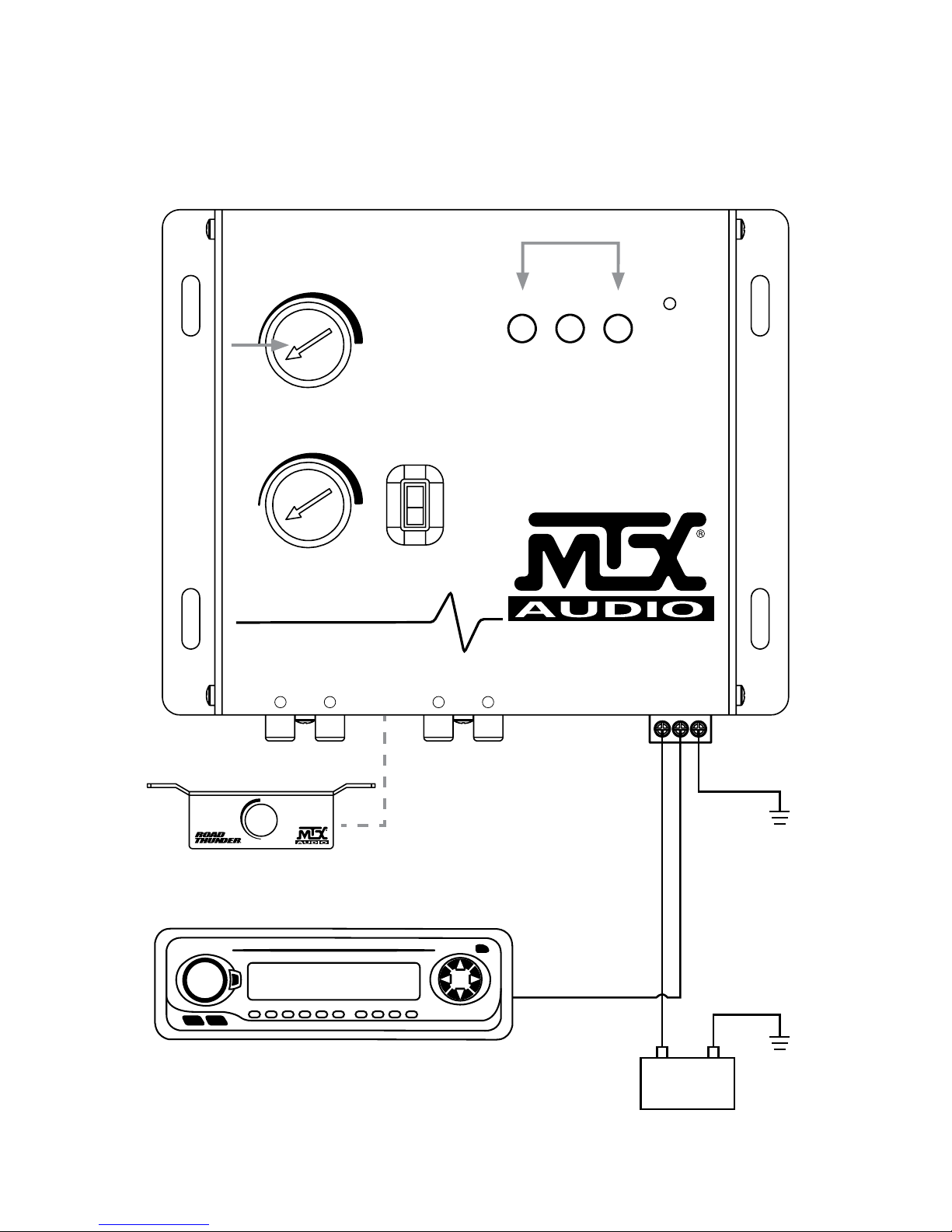
FUNCIONES DE CONTROL
1. Entradas - Las entradas utilizan un circuito de entrada equilibrada para ayudar a minimizar
el ruido inducido. También están diseñados para manejar muy altos voltajes de señal de hasta 15
voltios.
2. Salidas - Las salidas deben estar conectados a un componente, como un crossover, ecualizador,
o amplicador. Nota: El RTLDBP debe estar en línea antes de un crossover.
3. Control remoto que se monta al tablero
4. Conector de alimentación
5. Controles Para-Bass - Los dos mandos controlan las funciones para-Bass del RTLDBP. El mando
BARRIDO recoge la frecuencia central deseada para maximizar. El mando ANCHA ajusta el
ancho de un rango de frecuencia de la RTLDBP afectará.
6. PFM interruptor ltro subsónico - El RTLBDP utiliza un conmutador de ltro subsónico PFM que
ayudará con el control de altavoz y de gestión de energía. El interruptor de ltro subsónico PFM
viene con tres selecciones de frecuencia: 35Hz / 50Hz / 80Hz. En la mayoría de los sistemas,
poniendo el interruptor en 35Hz está bien. Un ajuste de frecuencia más alta proporcionará aún
más protección a su sistema. A menudo, una mayor frecuencia en realidad suena más fuerte y
más limpio.
7. Bajo indicadores maximizador: Estos tres indicadores LED parpadean cuando se activa el
circuito de la maximización de graves.
8. Encendido LED
9. Los puentes de conexión a tierra de entrada - Para la mayoría de los sistemas el puente se puede
dejar en la posición de equilibrio. En algunos sistemas, la unidad fuente puede buscar un
terreno a través de los conectores RCA. En este caso, los puentes deben moverse a la posición
desequilibrada.
10. Puentes de aislamiento de tierra - Ocasionalmente zumbido del alternador puede aparecer en un
sistema porque la unidad de la fuente y el amplicador pueden utilizar diferentes a tierra.
Conexiones a tierra alternativos se han proporcionado para ayudar en esta situación. Asegúrese
de que el sistema esté apagado antes de retirar estos puentes.
11. Puentes de control de salida de graves - No todos los sistemas están diseñados de la misma.
Algunos están diseñados exclusivamente para SPL (nivel de presión sonora), mientras que otros
son un poco más dócil. El circuito Bass Maximizer puede o bien aumentar o disminuir el voltaje
de la señal de la Restauración Circuito Bass. Dependiendo del sistema, estos puentes se pueden
cambiar a un ajuste más alto o más bajo para maximizar la salida de graves y proteger sus
altavoces. En la mayoría de los sistemas de la conguración de fábrica debe estar bien. Se
recomienda probar el establecimiento de la primera fábrica.