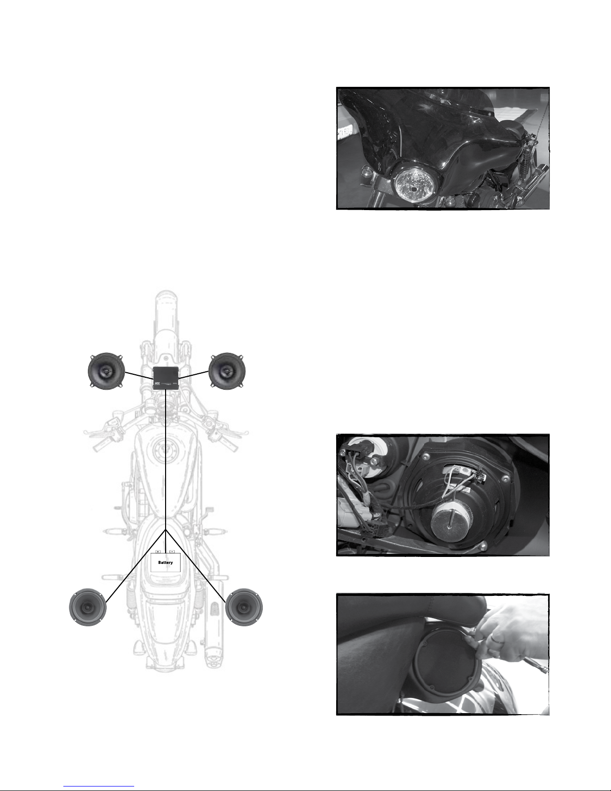
B- Connect the speaker output wires to the new speakers mounted to the
bike. Also make sure to keep the clutch side and brake connectors
directed to the correct side. The speaker output wires are marked with a
tag indicating clutch or brake and have female fastons on each end that
will connect to the new speaker.
C- Unplug the stock wire connected to the center of the cigarette lighter. Then
plug in the blue wire from the MTX wire harness into the cigarette lighter, and
then plug the stock cigarette lighter wire connector into the extra connector
on the MTX wire harness.
D- Turn the gain to 3⁄4 and switch the filter to high pass for both channels use
the 80Hz setting for the front channel.
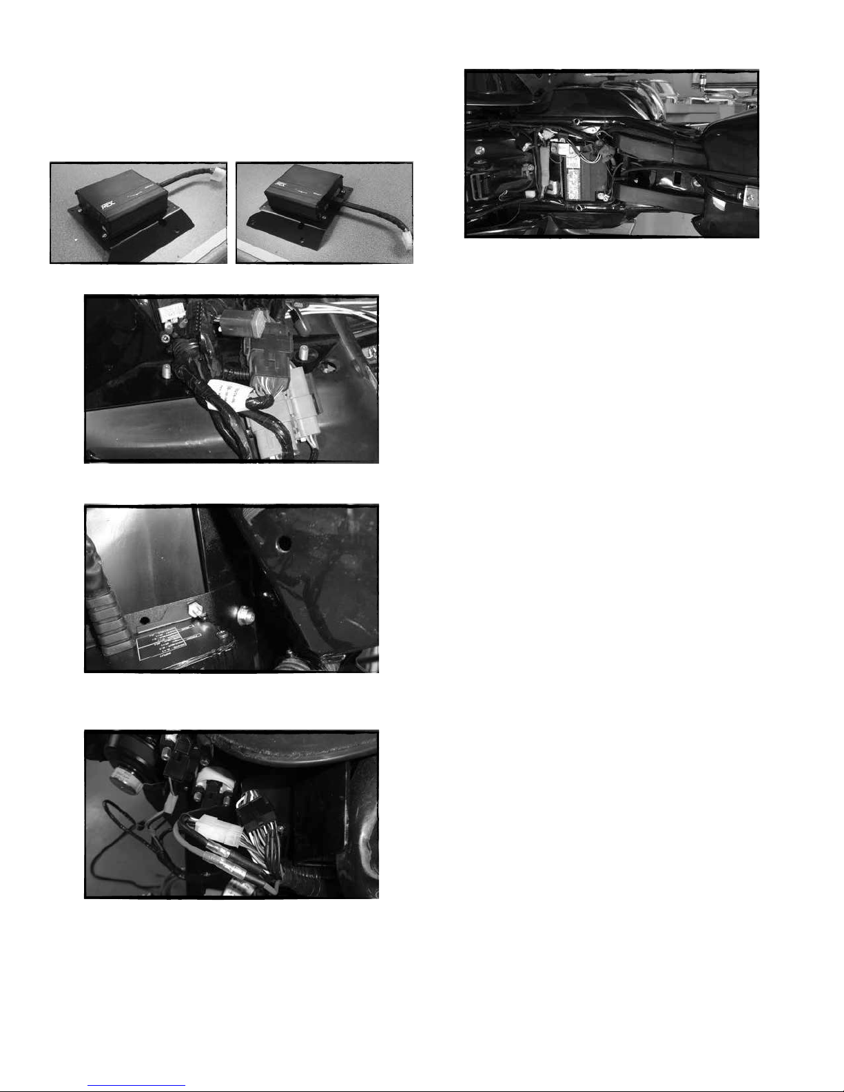
E- Place Hook and loop fastener on bottom of the amplifier, and the top of the
radio.
a. If the radio does not have any modules on the top place the amplifier
with the wire harness pointing towards the brake side and make
sure the amp is pushed as far back on the radio as possible.
b. If the radio does have a module on the top place the Hook and loop fastener on the
open side of the radio. Place the amplier with the wire harness
pointing forward. The amp should be pushed back as far as possible
to keep it from interfering with the fairing.
F- Connect the amplier connections to the MTX wire harness. There are 4
connections, 2 large rectangular connectors, and 2 bullet power connectors.
Take care to keep the power wire polarity correct. Red to Red, Black to Black.
a. Make sure the connections are securely snapped together.
G- Open fuse holder and place the 15 amp fuse in the holder.
H- Turn the bike to ACC and test to make sure the amp and speakers power up.
If all works properly, reverse the process to put the fairing back in place.
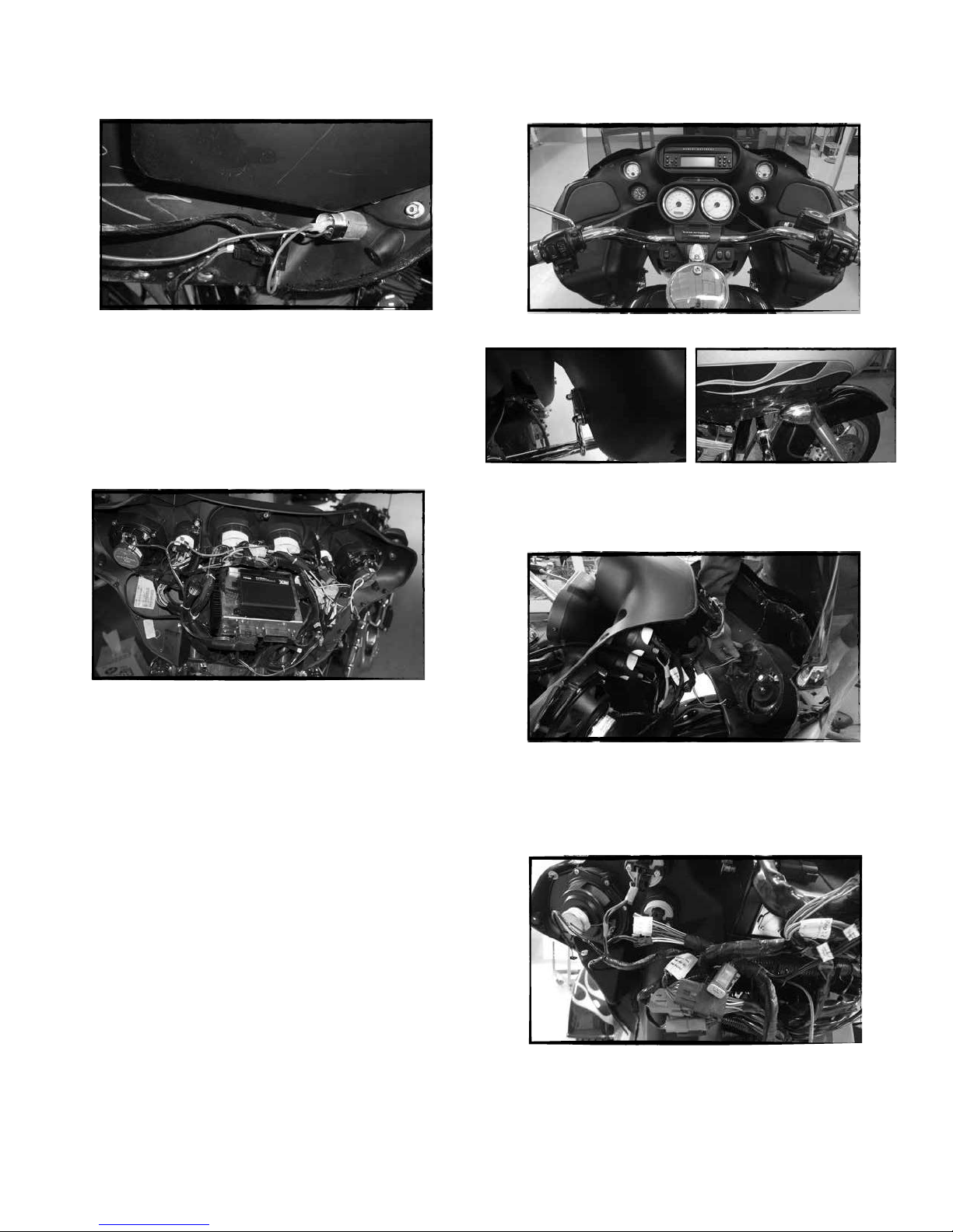
ROAD GLIDE AND ROAD GLIDE ULTRA INSTALLATION
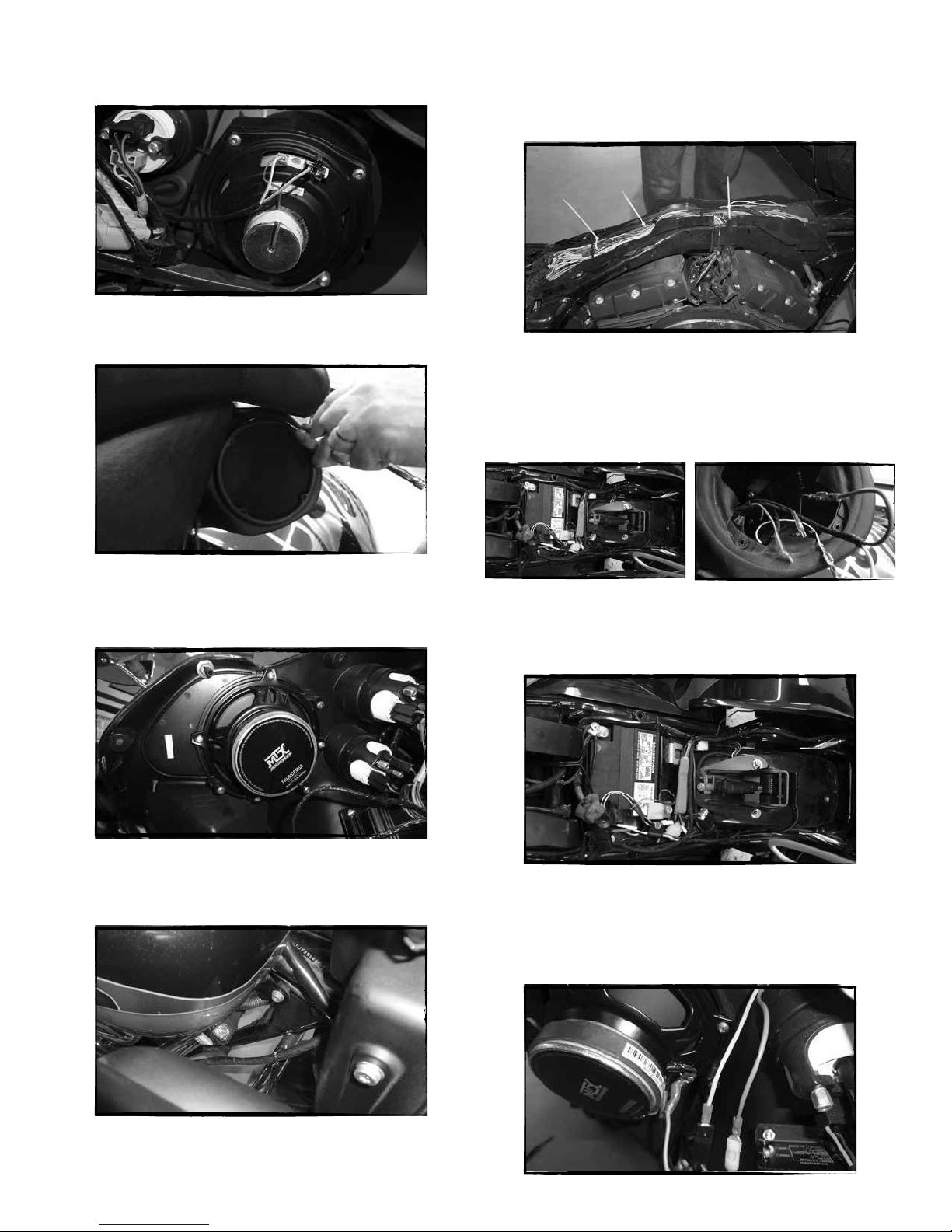
First Step - Fairing Removal
A- Remove the 6 bolts on the bottom sides of the fairing. This will allow the
fairing to be removed.
B- Remove the right and left turn signals.
C- Pull the fairing forward and up slightly, the harness connecting the headlight will
need to be disconnected too completely pull the fairing away from the bike.
a. Take care to not bump the fairing against the signal or extra lights
connected to the front forks.
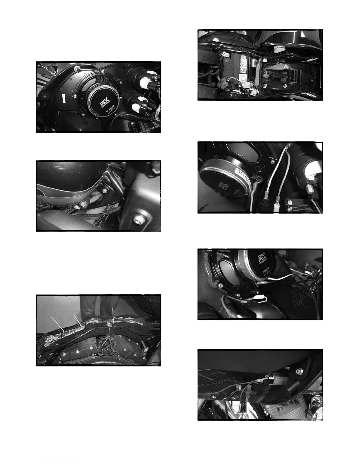
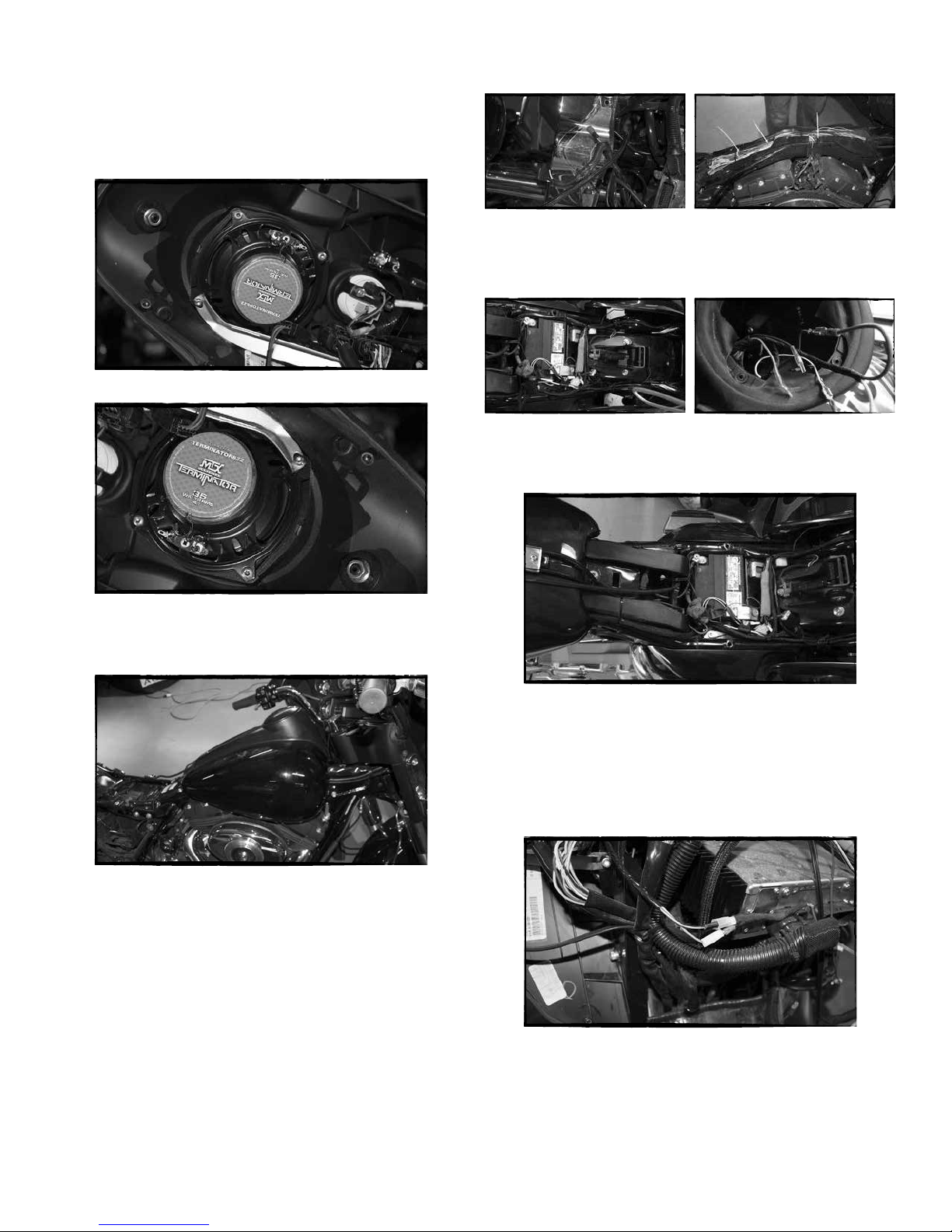
Second Step - Speaker Removal
A- Remove the speaker wire connectors from the speakers, take care to pull
them from the plastic connector and not the wires so that the stock wire
harness is not damaged.
B- Use a Torx driver to loosen the 4 screws holding on the stock speakers.
C- Keep track of which wires go to the clutch and brake side speakers.
-8-