5
Disassembly / Reassembly Instructions
HG-8 WARM CLIMATE FLUSHING SYSTEM
TOOLS NEEDED: Philips screwdriver, at-head screwdriver, HG-20087 T-handle wrench
HG-8 DISASSEMBLY AND REASSEMBLY INSTRUCTIONS
4. To prevent the loss of the
solenoid plunger and spring, place
an object or have a finger over
the plunger of the solenoid. Allow
the plunger enough space to kick
out of the solenoid body into the
object or finger hovering over it.
5. If test is successful, return
the flush / meter assembly to its
operating position below grade.
6. Return insulation pad and cast
iron meter lid to their
proper positions.
If everything checks out, the
electrical system is in
working order.
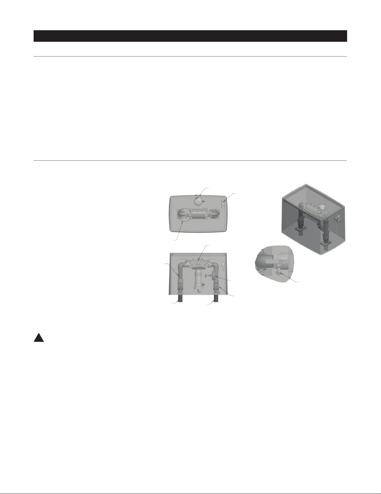
Valve Disassembly and Check
1. Remove six (6) bolts from
top cover.
2. Slowly pull cover off the valve.
3. Remove rubber diaphragm and
inspect for holes or worn areas.
4. Be certain to avoid contacting
the EPDM rubber diaphragm with
pipe putty. Pipe putty can cause
the rubber to thin out and leak.
5. Remove the valve screen plug
on the lower half of the valve body.
Be careful not to exert too much
force when pulling plug out.
6. Check for debris in the valve
screen on the inlet side with the
lower half of the valve body by
removing the valve screen plug.
7. Return valve plug to its
proper location when debris screen
is cleared.
8. Replace the top cover back onto
the diaphragm – make sure to line
up the openings in both.
9. Match up the top cover of the
valve with the bottom portion.
The arrows have to align on both
portions.
10. Replace the bolts and
tighten down.
Although the Hydro-Guard HG-8
Warm Climate Sub-Surface
Unit was delivered completely
assembled, it may be necessary
and/or desirable to disassemble
portions of the Unit, or the Unit
in its entirety, in order to allow for
required service and maintenance.
If disassembly is necessary,
please follow the directions below.
Always close the curb stop before
working on the unit.
Disassembly
1. Shut off water supply to
the unit and remove the green
housing cover.
2. Remove the composite lid
of HG-8 protective ground
sleeve vault.
3. Backup to stress point then
push down on the camlock
release handles to disengage
the camlocks prior to lifting the
flushing components out of
the device.
4. Raise and remove the flushing
system assembly out of the
meter box.
5. Modular design of valve and
double check valve allow for
service to be completed without
removal of the devices’ bodies
from the piping assembly.
Electrical System Check
1. Pull internals of HG-8 out of
in-ground protective vault.
2. Unscrew solenoid from valve –
be careful to not drop the
solenoid plunger and spring into
in-ground housing.
3. Using the Bluetooth Controller,
run a 2 minute manual flush
seequence.
NOTE: Plunger inside solenoid
should be down when running and
up when off.
WARNING: Avoid overuse of
pipe sealant and never allow
sealant to come into contact with
EPDM rubber diaphram.
Reassembly
1. If any disassembly has been
conducted of the control valve and/
or double check valve, verify that all
bolts are properly tightened. Check
assemblies for leakage prior to
lowering flushing / metering assembly
back into position below grade.
2. Using lifting holes and/or lifting
strap on steel plate, lower flushing
assembly below grade by slowly
lowering the steel frame to the lower
part of the in-ground protective
housing (DO NOT apply excessive
force to assembly). Use Guide in
meter box to allign internols.
3. Once lowered back into the
pretective vault, lock the internals
in place by pulling up on camlock
handles.
4. Turn water supply to the unit
on. Using the controller, run a two
minute manual flushing procedure
to confirm all components
are operational.
5. Return insulation pad and lid to
their proper location.
!