(L)
70/
t-7';J/'51
t-
(03
~)
front
upright
(Bag-D3)
70/t-0'7-7-.b.
front
lower
arID
(E'eg--{J5)
~$o~CD~~
(R)
M~~dJ.Qliiil;:'
~$:,cc<7.)~~~G
"(fJ'6
M~
~d.>"t'T~L
'0
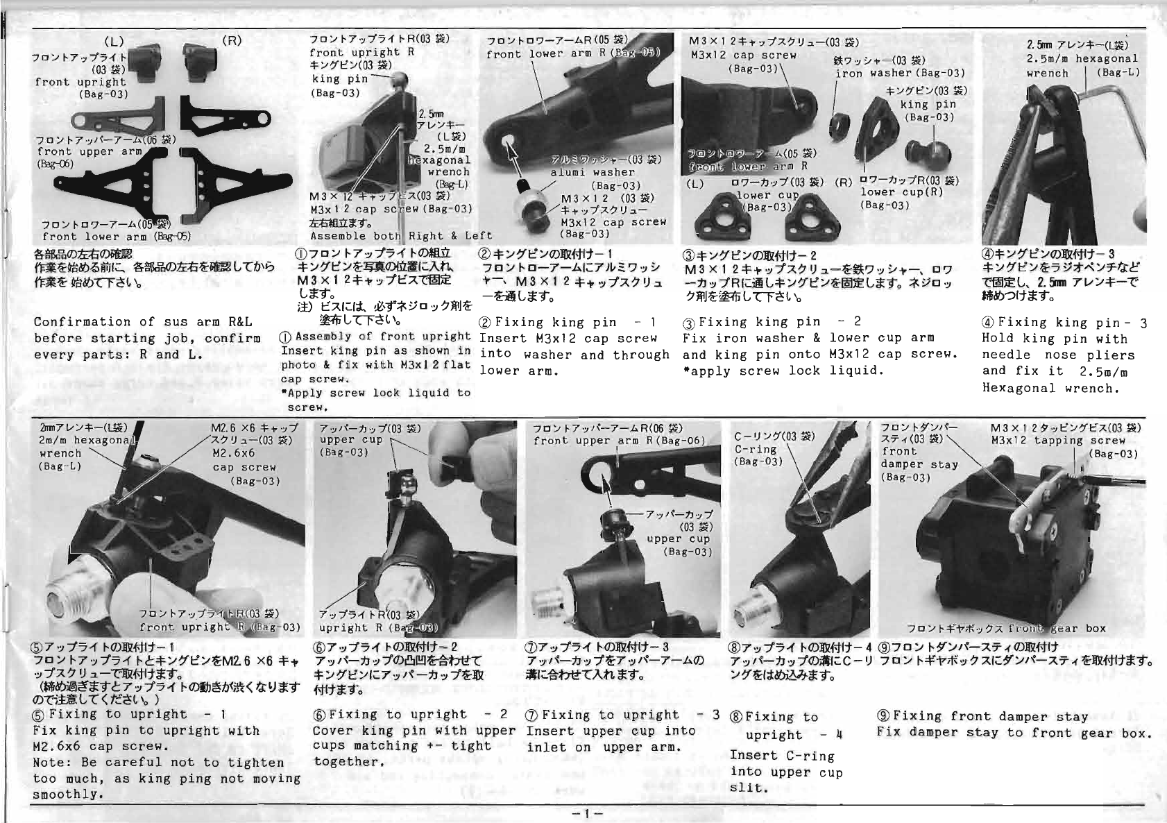
Confirmation
of
sus
arm
R&L
before
starting
job,
confirm
every
parts:
Rand
L.
70/
t-7
'
;J/'51
t-
R(03~)
front
upright
R
~/?"t/(03
~)
king
pin
(Bag-
D3)
2.m
l//~
(L~)
2.5m/m
xagonal
wrench
a umi
washer
(Eag-L) . / (Bag-
D3)
M3
03
~)
M3 x 1 2
(03~)
M3x
12
cap
s w(Bag-D3)
~1-';J/7..?I),,-
~a::9o
M3x12
cap
screw
Assemble
bo
Right
&
Left
(Bag-D3)
CD
7D
;.I
1-7,,,
:f'5-f
1-<DmJ'l
(2)
~
;.I~t::/CD1IlZ#11-
1
~;.I~t::/~UO){lril'l;:Att.
70;.1
I-
0-7-1>.1;:7
)!I~?
':J
~
M3X12~T',,:ft::X(~:iE
T-,
M3X12~T',,:fA?I).:I.
Ga;:90
-H
G
a;:
90
)i)
CAI;:I-;l
~\~"*~D
'"
?~J~
~L'-'Cr~L
'0
(2)
Fixing
king
pin
- 1
CD
Assembly
of
front
upright
Insert
M3x12
cap
screw
Insert
king
pin
as
shown
in
into
washer
and
through
photo
&
fix
with
M3x
12
flat
lower
arm.
cap
screw.
-Apply
screw
lock
liquid
to
screw.
M 3 x 1
2~1-
';J/7..?
I)
,,-(03
~)
M3x12
cap
screw
(Bag-D3)
~'7';J~1--(03
~)
washer
(Bag-
D3)
~
/?"
t::
/(03
~)
king
pin
(Bag-D3)
(L)
0'7-n
'
;J/(03~)
(R)
0'7-n';J/R(03~)
lower
cup(R)
(Bag-D3)
G)
~
/~I::'/CD1IlZ#11-
2
M3XI2~T':J:fA?I)':"-~.?':J~T~
D?
-t.J,,,
:fRI;:~G~;.I?·I::';.I~~~Ga;:90
*YO
'"
?~J~~G
"Cl'c!L
'0
G)
Fixing
king
pin
- 2
Fix
iron
washer
&
lower
cup
arm
and
king
pin
onto
M3x12
cap
screw.
-apply
screw
lock
liquid.
2.m
7l//~-(~)
2.5m/m
@
:j:;.I~I::'/CD1IlZ#11-
3
~/~I::'/~'5~;tA:;.I=rt.rc
c~~G,
2.5nm
7v;.l~-C'
MdJ-::>
11
a;:
90
@
Fixing
king
pin
- 3
Hold
king
pin
with
needle
nose
pliers
and
fix
it
2.5m/m
Hexagonal
wrench.
mm7l//~-(~)
2m/m
hexagon
wrench
(Bag-
L)
M2
. 6 x6
~
i'
';J
/
?
I)
,,-(03
~)
M2.6x6
70
/
t-7
·
;J/~-7-.b.R(06
~)
front
upper
arID
R(Bag-D6
70/t-:$f/1~-
7..7'·d03
~)
front
damper
stay
(Bag-D3)
M 3 x 1
29
';J
t/?"!::"7..(03
~)
M3x12
tapping
screw
®7,,,:f'5-f
I-CD1IlZi-t11-1
70/1-7':J:f'5-fI-~~/~I::'/~M26X6~T
,,,:fA?
I)
.:..-C'1IlZ#11a;:90
(Mi~~a;:9
~
7 '"
:f'5-f
I-CDIh~fJ<j!I{<
t.rlJ a;:9
CDci±'~
G
"(
<
t::.c!
L
'0
)
®
Fixing
to
upright
- 1
Fix
king
pin
to
upright
with
M2.6x6
cap
screw.
Note:
Be
careful
not
to
tighten
too
much,
as
king
ping
not
moving
smoothly.
@
7,,,:f'5-f
I-CDI!l1#Ij'- 2
7
':J
1~-t.J
'"
:fCD81!!l~bt~T
:j:
;.I~I::'/I;:
7
':J
I~
-t.J
'"
:f~1Iil
#11a;:90
@
Fixing
to
upright
- 2
Cover
king
pin
with
upper
cups
matching
+-
tight
together.
(])7,,,
:f'5-f
HD1Ii#11- 3
7
':J1'\-t.J
'"
:f~7
,,,/'\-7-1>.CD
~1;:~btt,,(An
a;:90
,(Bag-03)
70
/
t--¥,~;j{
'
;J?
7..
f
®
7'"
:f'5-f
I-CD]lJZHI1-
4
®7
0
;.l
I-
~/I~-
AT'(
CD1fil#11
7
,,,/~-t.J
'"
:fCD;'lI;:C
-I)
70/
I-=¥i"*
':J?
AI;:~/I~-AT.(
~]lJZ#11a;:90
/?,'~I~~Ma;:90
(])
Fixing
to
upright
- 3 ®
Fixing
to
®
Fixing
front
damper
stay
Insert
upper
cup
into
upright
-4
inlet
on
upper
arm.
-1-
Insert
C-ring
into
upper
cup
slit.
Fix
damper
stay
to
front
gear
box.