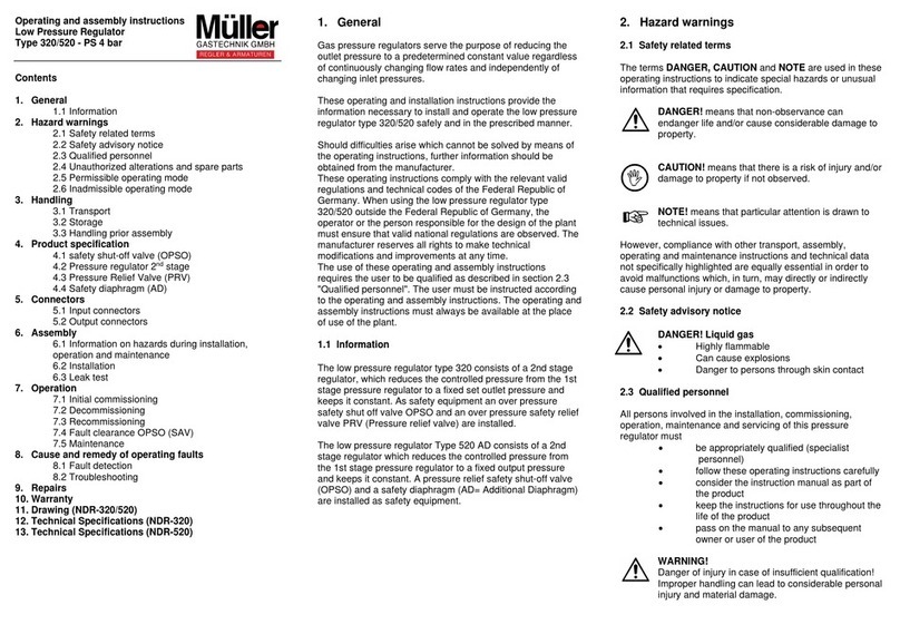
Muller 110 Product guide

Operating and assembly instructions
Tank regulator combination
Type 110/111 - PS 25 bar
Contents
1. General
1.1 Information
2. Hazard warnings
2.1 Safety related terms
2.2 Safety advisory notice
2.3 Qualified personnel
2.4 Unauthorized alterations and spare parts
2.5 Permissible operating mode
2.6 Inadmissible operating mode
3. Handling
3.1 Transport
3.2 Storage
3.3 Handling prior assembly
4. Product specification
4.1 safety shut-off valve (OPSO)
4.2 Pressure regulator 1st stage
4.3 Pressure Relief Valve (PRV)
4.4 Pressure regulator 2nd stage
4.5 Emergency supply (Type 111)
5. Connectors
5.1 Input connectors
5.2 Output connectors
6. Assembly
6.1 Information on hazards during installation,
operation and maintenance
6.2 Installation
6.3 Leak test
7. Operation
7.1 Initial commissioning
7.2 Decommissioning
7.3 Recommissioning
7.4 Fault clearance OPSO (SAV)
7.5 Maintenance
8. Cause and remedy of operating faults
8.1 Fault detection
8.2 Troubleshooting
9. Repairs
10. Warranty
11. Drawing
12. Technical specifications
1. General
Gas pressure regulators serve the purpose of reducing the
outlet pressure to a predetermined constant value regardless
of continuously changing flow rates and independently of
changing inlet pressures.
These operating and installation instructions provide the
information necessary to install and operate the container
regulator combination type 110/111 safely and in the
prescribed manner.
Should difficulties arise which cannot be solved by means of
the operating instructions, further information should be
obtained from the manufacturer.
These operating instructions comply with the relevant valid
regulations and technical codes of the Federal Republic of
Germany. When using the tank regulator combination type
110/111 outside the Federal Republic of Germany, the
operator or the person responsible for the design of the plant
must ensure that valid national regulations are observed. The
manufacturer reserves all rights to make technical
modifications and improvements at any time.
The use of these operating and assembly instructions
requires the user to be qualified as described in section 2.3
"Qualified personnel". The user must be instructed according
to the operating and assembly instructions. The operating and
assembly instructions must always be available at the place
of use of the plant.
1.1 Information
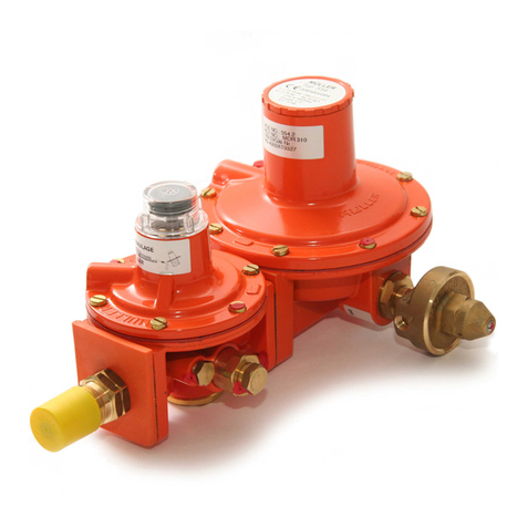
The tank regulator combination type 110/111 consists of a 1st
stage regulator and a 2nd stage regulator, which reduces the
unregulated pressure from the LPG tank to a fixed set outlet
pressure and keeps it constant. As safety equipment, an
overpressure safety shut-off valve (OPSO) and an
overpressure safety relief valve (PRV) are installed.
2. Hazard warnings
2.1 Safety related terms
The terms DANGER, CAUTION and NOTE are used in these
operating instructions to indicate special hazards or unusual
information that requires specification.
DANGER! means that non-observance can
endanger life and/or cause considerable damage to
property.
CAUTION!means that there is a risk of injury and/or
damage to property if not observed.
NOTE!means that particular attention is drawn to
technical issues.
However, compliance with other transport, assembly,
operating and maintenance instructions and technical data
not specifically highlighted are equally essential in order to
avoid malfunctions which, in turn, may directly or indirectly
cause personal injury or damage to property.
2.2 Safety advisory notice
DANGER! Liquid gas
•Highly flammable
•Can cause explosions
•Danger to persons through skin contact
2.3 Qualified personnel
All persons involved in the installation, commissioning,
operation, maintenance and servicing of this pressure
regulator must
•be appropriately qualified (specialist
personnel)
•follow these operating instructions carefully
•consider the instruction manual as part of
the product
•keep the instructions for use throughout the
life of the product
•pass on the manual to any subsequent
owner or user of the product
WARNING!
Danger of injury in case of insufficient qualification!
Improper handling can lead to considerable personal
injury and material damage.

2.4 Unauthorized alterations and spare parts
Modification or alteration of the tank regulator combination
type 110/111 is not permitted. Original drawings and
accessories authorised by the manufacturer serve for safety.
The use of other parts or unauthorised modifications to the
type 110/111 tank regulator combination by third parties
invalidates the manufacturer's liability for the consequences.
2.5 Permissible operating mode
•liquid gas (gas phase), others on request
•ex zone 1 or 2
•under the container cover (above ground,
underground), in weather-protected outdoor areas,
•in buildings and special installation rooms (according
to TRF 2012)
2.6 Inadmissible operating mode
•ex-zone 0
•operating modes that deviate from the permissible
operating modes and technical data
3. Handling
3.1 Transport
During all transportation, the generally recognised rules of
technology and the accident prevention regulations must be
strictly observed.
Handle the goods to be transported with care. During
transport, the pressure regulator must be protected against
shocks, blows or vibration.
Immediately after receipt of the goods, the delivery must be
checked for completeness and transport damage.
See also section 9.0.
3.2 Storage
If the pressure regulator is not installed immediately upon
delivery, it must be stored properly.
Storage temperature -20°C to +60°C, dry, free of dirt and
protected from moisture.
3.3 Handling prior assembly
•Protect from weather influences such as wetness
•Make sure that the product is free from dust and
foreign particles
4. Product specification
4.1 Safety shut-off valve (OPSO)
The overpressure safety shut-off device OPSO is open during
normal operation and is designed to shut off the gas flow
automatically as soon as the set response pressure is
reached in order to protect downstream equipment from
impermissibly high pressure. It must be opened manually
after closing (see OPSO restart).
4.2 Pressure regulator 1st stage
The 1st stage pressure regulator reduces the unregulated
pressure from the liquid gas container to a set outlet pressure.
4.3 Pressure Relief Valve (PRV)
The PRV (Pressure Relief Valve) is closed during normal
operation and is designed to automatically release the gas
flow with limited flow when the pressure in the system to be
protected reaches the set pressure. This is relieved via the
regulator's venting port. It closes again automatically when
the pressure drops below the set pressure.
The outlet opening must be protected against rainwater.
It is important to note that pressure regulators which
are operated inside a building, an enclosure or a
hazardous area must be provided with a vent line to
the outside.
Please observe this information, otherwise liquid gas
can escape in the building, which may lead to an
explosion.
Insect screen with filter screen must be screwed into
the vent on the regulator. It must be checked
regularly whether the screen is free from dirt. A
clogged screen can lead to increased or too low
outlet pressures and thus to a response of the
OPSO.
4.4 Pressure regulator 2nd stage
The pressure regulator of the 2nd stage reduces the output
pressure of the pressure regulator of the 1st stage to a fixed
output pressure of 50 mbar.
4.5 Emergency supply (Type 111)
If the gas tank should unexpectedly run out of gas, the gas
supply can be secured by means of a gas cylinder via the
emergency supply connection using a high-pressure hose.
This is not a permanent solution. It only serves as a
temporary solution until the gas tank is filled again.
5. Connectors
5.1 Input connectors
•Cylindrical female threads:
G.37 = G 1/4”, G 3/8”, G 1/2”, G 3/4”, G 1”
•Large cylinder connection:
G.4 = W 21,8 x 1/14 LH
•POL Connection:
G.9
•Cutting ring fitting RVS:
G.22 = 12mm, 15mm, 18mm, 22mm, 28mm
Other connections on request!
5.2 Output connectors
•Cylindrical female threads:
H.22 = G 1/4”, G 3/8”, G 1/2”, G 3/4”, G 1”
•Cutting ring fitting RVS:
H.8 = 12mm, 15mm, 18mm, 22mm, 28mm
•Compression fitting PVS:
H.10
•Soldering screw connection LVS:
H.10
6. Assembly
6.1 Information on hazards during installation, operation
and maintenance
DANGER!
Safe operation of the pressure regulator is only
guaranteed if it is installed and commissioned by
qualified personnel (see point 2.3 "Qualified
personnel") in accordance with the warnings in this
operating manual. Proper use of tools and protective
equipment must be ensured. The operating
instructions of the pressure regulator must be
observed during all work on the pressure regulator or
when handling the pressure regulator.

6.2 Installation
In addition to the generally applicable installation guidelines,
the following points must be observed:
•current TRF (private area)
•accident prevention regulation DGUV 79 +80
(commercial sector)
•corresponding DVGW worksheets
NOTE!
The installation position of the pressure regulator
must be carried out according to the enclosed
support device. It is also important to note that the
installation position of the vents must be selected in
such a way that any water accumulation can drain
off.
The interior of the pipeline must be free of foreign
particles.
A tension-free installation must be ensured.
The pressure regulator must not serve as a fixed
point; it is supported by the pipeline system.
Observe flow direction (marked by an arrow on the
product).
The pressure regulator must be mounted and
protected in such a way that dripping water cannot
penetrate. When mounting on an underground liquid
gas tank, we recommend a ventilation set (art. no.: 9
03 110 8 5 000 2). If the pressure regulator is used
outdoors, it must be mounted under the protective
cover or in a protective box.
•When tightening the POL connection, avoid any
force on the pressure regulator.
•Prevent sealant from penetrating the gas-carrying
components.
•For threaded connections, always use a suitable
spanner to counteract.
•After assembly a careful leak test must be carried
out.
6.3 Leak test
CAUTION: The control device must not be
included in a strength test (design review) of the
entire installation.
•Close all shut-off valves of the connected devices.
•apply test pressure according to TRF 2012
•wait for temperature adjustment
•test duration 10 minutes (the pressure must not
drop)
•spray all connections with foaming agents (e.g. leak
detection spray) and check for leaks
NOTE!
We recommend the leak test with our testing device
(Art. No.: 1 00 098 14 018 2)
DANGER!
•Before each commissioning of a new installation or
recommissioning of an installation after repairs or
modifications, the following must be ensured:
•proper completion of all installation/assembly work!
•commissioning only by "Qualified personnel "(see
point 2.3).
•passed leak test
7. Operation
7.1 Initial commissioning
After completion of the leak test the pressure regulator is
ready for operation.
7.2 Decommissioning
If the supply and consumption system is to be taken out of
operation, all shut-off valves must be closed and the pipe
system drained. All open connections must be secured with a
suitable seal.
7.3 Recommissioning
When recommissioning the regulator, make sure that all the
relevant steps are repeated as described in section 6.1 to
section 6.3.
If recommissioning is not possible, the manufacturer must be
informed.
7.4 Fault clearance OPSO (SAV)
If the OPSO has locked, indicated by the visual indicator
(red), the following steps are required:
•Close the tapping valve on the liquid gas container
•Relieve the pressure on the pressure regulator (on
the inlet and outlet side)
•Turn off the OPSO display
•Place the OPSO plunger with the enclosed lever tool
on the red indicator and pull it out until it engages
•After rectifying the fault, open the gas outlet valve
7.5 Maintenance
If the points in section 6 are observed, the pressure regulator
is maintenance free.
8. Cause and remedy of operating faults
8.1 Fault detection
DANGER!
When troubleshooting, the hazard warnings
under 2 must be observed.
•If the faults cannot be rectified using the following
table "Troubleshooting (8.2)", the manufacturer must
be consulted.
•In case of malfunctions of the function or the
performance, it must be checked whether the
installation work has been carried out and completed
according to these operating instructions.
•The information on pressure, temperature, and
direction of flow as well as the operating conditions
must correspond to the data sheet or the technical
data on the type plate
8.2 Troubleshooting
Fault
Measures
Gas smell
Caution: Fire and
explosion hazard!
Keep calm, close the gas supply,
open windows and doors, do not
operate any electrical switches,
contact a specialist
No gas flow
Open shut-off valves, check level
indicator if necessary,
OPSO is closed (see
Recommissioning OPSO), check
the filter in the inlet connection as
well as the vent openings and clean
if necessary or contact the
manufacturer.
Consumption
appliance on fault
After depressurising the system,
connect the "Müller test unit" to the
appropriate test connections on the
regulator and take measurements:
•inlet pressure (upstream
pressure before the controller
stage)
•outlet pressure (idle pressure,
consuming device not in
operation
•outlet pressure (flow pressure,
consumer unit in operation)
•connection pressure at the
consumer unit
Then compare the values with the
technical data of the regulator and
the consumer unit.

Fault
Measures
OPSO falls
continuously or
cannot be unlocked
Pressure regulator is defective,
please replace.
NOTE!
Before carrying out assembly and repair work,
please observe Section 10
9. Repairs
In order to ensure the proper functioning of the installation
under normal operating conditions, it is recommended to
replace the device before 10 years have elapsed since the
date of manufacture.
The 10 years is a recommendation that can be replaced by
national laws or technical regulators, taking into account the
operating conditions of integrated safety devices and
maintenance schedules.
According to DGUV 79:
The Contractor must ensure that parts of consumable
equipment that are subject to wear and aging are replaced
after a maximum of 8 years. This does not apply if the proper
condition has been confirmed by an expert.
10. Warranty
The scope and period of warranty is defined in the version of
the "General Terms and Conditions" of Müller Gastechnik
GmbH valid at the time of delivery.
All information and notes in this manual have been compiled
taking into account the applicable standards and regulations,
the state of the art and our many years of expertise and
experience. The manufacturer accepts no liability for
damages due to:
•Non-compliance with the instructions
•Unintended use
•Use of untrained personnel
•Unauthorised conversion
•Technical changes
•Use of non-approved spare parts. The actual scope
of delivery may differ from the explanations and
illustrations described here in the case of special
versions, the use of additional ordering options or
due to the latest technical changes.
11. Drawing (BRK-110/111)
1. inlet connection Pol
2. OPSO (SAV) vent opening
3. overpressure safety shut-off device OPSO (SAV)
4. visual display OPSO
5. ventilation outlet regulator
(connection for insect screen) Internal overpressure
safety relief valve
6. low pressure regulator 2nd stage
7. outlet connection G 1/2 "IG
8. test device back pressure, 8mm hose connection from
"Müller test device”
9. test device inlet pressure G 1/4" (for type 111 via
emergency supply connection G 3/8" LH-KH
10. medium pressure regulator 1st stage
1. inlet connection Pol
2. ventilation opening medium pressure regulator
3. medium pressure regulator 1st stage
4. low pressure regulator 2nd stage
5. outlet connection G 1/2 "IG
6. test device back pressure, 8mm hose connection
from "Müller test device"
7. ventilation blow-off opening regulator (connection for
insect screen) internal overpressure safety blow-off
valve
8. test device inlet pressure G 1/4" (for type 111 via
emergency supply connection G 3/8" LH-KH
9. vent opening OPSO (SAV)
10. visual display OPSO
12. Technical specification (BRK-110/111)
Max. permissible
pressure:
PS 25
Response
pressure
OPSO:
132
mbar
Nominal flow
Mg:
10 kg/h
Response
pressure PRV:
150
mbar
Inlet pressure
p:
3-16 bar
Connection at
inlet
Pol
Nominal outlet
pressure pd:
50 mbar
Connection at
outlet
G 1/2”
Pressure loss:
ΔP 5
Temperature
range
-40 °C
to
+80 °C
This manual suits for next models
1
Other Muller Controllers manuals