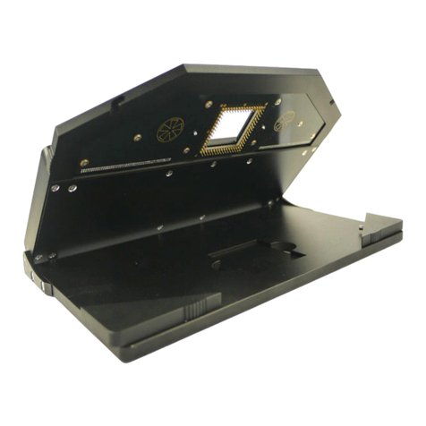
Multi Channel Systems MEA Series User manual

i
MEA Amplifier
for Inverse Microscopes
Manual

ii
Information in this document is subject to change without notice.
No part of this document may be reproduced or transmitted without the express written
permission of Multi Channel Systems MCS GmbH.
While every precaution has been taken in the preparation of this document, the publisher
and the author assume no responsibility for errors or omissions, or for damages resulting
from the use of information contained in this document or from the use of programs and
source code that may accompany it. In no event shall the publisher and the author be liable
for any loss of profit or any other commercial damage caused or alleged to have been caused
directly or indirectly by this document.
© 2020 Multi Channel Systems MCS GmbH. All rights reserved.
Printed: 06. 11. 2012
Multi Channel Systems
MCS GmbH
Aspenhaustraße 21
72770 Reutlingen
Germany
Phone +49-71 21-90 92 5 - 0
Fax +49-71 21-90 92 5 -11
sales@multichannelsystems.com
www.multichannelsystems.com
Microsoft and Windows are registered trademarks of Microsoft Corporation. Products that
are referred to in this document may be either trademarks and/or registered trademarks of
their respective holders and should be noted as such. The publisher and the author make
no claim to these trademark.

3
Table of Contents
Introduction 5
About this Manual 5
Important Information and Instructions 7
Operator's Obligations 7
Guarantee and Liability 7
Important Safety Advice 8
First Use of the MEA Amplifier 9
Welcome to the MEA Amplifier 9
Setting Up and Connecting the MEA Amplifier 10
First Tests and Tutorial 11
First Functional Tests 11
General Performance / Noise Level 11
Operating the MEA Amplifier 13
Signal Amplification and Filters 13
Temperature Control 14
Mounting the MEA Probe and Grounding the Bath 15
Stimulation 17
Service and Maintenance 18
Troubleshooting 19
About Troubleshooting 19
Noise on Single Electrodes 19
Unsteady Baseline 20
Artifacts on All Channels 21
Liquid Spilled onto Amplifier 22
Technical Support 22
Appendix 23
Technical Specifications 23
MEA1060-Inv 23
Heating Element 24
Test Model Probe 24
Pin Layout 25
Pin and MEA Layout 25
Contact Information 27
Ordering Information 27
Index 33


5
1 Introduction
1.1 About this Manual
This manual comprises all important information about the first installation of the hardware
and software, and about the daily work with the instrument. It is assumed that you have already
a basic understanding of technical and software terms. No special skills are required to read this
manual.
If you are using the device for the first time, please read the important safety advice before
installing the hardware and software, where you will find important information about the
installation and first steps.
The printed manual and Help are basically the same, so it is up to you which one you will use.
The Help offers you the advantage of scrolling through the text in a non-linear fashion, picking
up all information you need, especially if you use the Index, and the Search function. If you are
going to read larger text passages, however, you may prefer the printed manual.
The device and the software are part of an ongoing developmental process. Please understand
that the provided documentation is not always up to date. The latest information can be found
in the Help. Check also the MCS web site (www.multichannelsystems.com) for downloading
up-to-date manuals and Help files.


7
2 Important Information and Instructions
2.1 Operator's Obligations
The operator is obliged to allow only persons to work on the device, who
are familiar with the safety at work and accident prevention regulations and have been
instructed how to use the device;
are professionally qualified or have specialist knowledge and training and have received
instruction in the use of the device;
have read and understood the chapter on safety and the warning instructions in this manual
and confirmed this with their signature.
It must be monitored at regular intervals that the operating personnel are working safely.
Personnel still undergoing training may only work on the device under the supervision
of an experienced person.
2.2 Guarantee and Liability
The General conditions of sale and delivery of Multi Channel Systems MCS GmbH always apply.
The operator will receive these no later than on conclusion of the contract.
Multi Channel Systems MCS GmbH makes no guarantee as to the accuracy of any and all tests
and data generated by the use of the device or the software. It is up to the user to use good
laboratory practice to establish the validity of his findings.
Guarantee and liability claims in the event of injury or material damage are excluded when
they are the result of one of the following.
Improper use of the device.
Improper installation, commissioning, operation or maintenance of the device.
Operating the device when the safety and protective devices are defective and/or inoperable.
Non-observance of the instructions in the manual with regard to transport, storage, installation,
commissioning, operation or maintenance of the device.
Unauthorized structural alterations to the device.
Unauthorized modifications to the system settings.
Inadequate monitoring of device components subject to wear.
Improperly executed and unauthorized repairs.
Unauthorized opening of the device or its components.
Catastrophic events due to the effect of foreign bodies or acts of God.

MEA Amplifier for Inverse Microscopes Manual
8
2.3 Important Safety Advice
Warning: Make sure to read the following advice prior to install or to use the device and the
software. If you do not fulfill all requirements stated below, this may lead to malfunctions or
breakage of connected hardware, or even fatal injuries.
Warning: Obey always the rules of local regulations and laws. Only qualified personnel should
be allowed to perform laboratory work. Work according to good laboratory practice to obtain
best results and to minimize risks.
The product has been built to the state of the art and in accordance with recognized safety
engineering rules. The device may only
be used for its intended purpose;
be used when in a perfect condition.
Improper use could lead to serious, even fatal injuries to the user or third parties and damage
to the device itself or other material damage.
Warning: The device and the software are not intended for medical uses and must not
be used on humans.
Malfunctions which could impair safety should be rectified immediately.
High Voltage
Electrical cords must be properly laid and installed. The length and quality of the cords must
be in accordance with local provisions.
Only qualified technicians may work on the electrical system. It is essential that the accident
prevention regulations and those of the employers' liability associations are observed.
Each time before starting up, make sure that the mains supply agrees with the specifications
of the product.
Check the power cord for damage each time the site is changed. Damaged power cords should
be replaced immediately and may never be reused.
Check the leads for damage. Damaged leads should be replaced immediately and may never
be reused.
Do not try to insert anything sharp or metallic into the vents or the case.
Liquids may cause short circuits or other damage. Keep the device and the power cords always
dry. Do not handle it with wet hands.
Requirements for the installation
Make sure that the device is not exposed to direct sunlight. Do not place anything on top of
the device, and do not place it on top of another heat producing device. Never cover the device,
not even partially, so that the air can circulate freely. Otherwise, the device may overheat.
Use and keep the device only in a dry environment. Fluids or damp air may damage or destroy the
device. Spilled liquid can damage or even completely destroy the electronics of the MEA amplifier.
Avoid it by all means.
Warning: The device must not get in contact with fluids! Spilled liquid can damage or even
completely destroy the electronics of the amplifier! This is eminently important when using
a perfusion system. Take care that the flow rates of the inlet and outlet flow match so that
flooding of the amplifier is efficiently prevented.

9
3 First Use of the MEA Amplifier
3.1 Welcome to the MEA Amplifier
Raw data from up to 60 electrodes of a microelectrode array (MEA) is amplified
by 60 channels of filter amplifiers that are built very small and compact using SMD
(Surface Mounted Devices) technology. The small-sized MEA amplifier combines the
interface to the MEA probe with the signal filtering and the amplification of the signal.
The compact design reduces line pick up and keeps the noise level down.
The MEA sensor is placed directly into the small-sized MEA amplifier. When the amplifier
is closed, the contact pins in the lid of the amplifier are pressed onto the MEA contact pads.
The very close location of the amplifier to the MEA sensor is very favorable concerning a high
signal-to-noise ratio.
MEA amplifiers can be ordered with different gain and bandwidth configurations by the user's
choice. For example, typical pass bands would be 1 to 300 Hz for recording field potentials and
300 to 3000 Hz for recording action potentials. It is also possible to use a broadband amplifier
and filter the data with the digital filter of the free MC_Rack program. Gain settings from
100 to 5000 are possible.
The amplifier is connected to the data acquisition computer via a single 68-pin MCS standard
cable. The analog output signals of the MEA amplifier are then acquired and digitized by the
MC_Card (MEA-System) or your custom data acquisition system.
MEA amplifiers have an integrated heating system for controlling the MEA's temperature.
The desired temperature can be easily programmed with a temperature controller. You will not
need an incubator during recording all environmental conditions are reliably controlled directly
in the MEA dish.
You can then simply ground bad or unwanted electrodes by toggling small switches on the
amplifier. You can also connect a stimulus generator to any electrode(s) for stimulation.
Amplifier inputs are grounded during stimulation to prevent a saturation of the amplifier.

MEA Amplifier for Inverse Microscopes Manual
10
3.2 Setting Up and Connecting the MEA Amplifier
Warning: Spilled liquid can damage or even completely destroy the electronics of the MEA
amplifier. Please be extremely careful when setting up your perfusion system and when starting
the perfusion. Take care that the flow rates of the inlet and outlet flow match so that flooding
of the amplifier is efficiently prevented.
Note: The housing of the MEA amplifiers was optimized for Zeiss Axiovert microscopes. MEA
amplifiers are compatible to most standard microscopes if the following prerequisites are met.
This MEA amplifier type has been developed for standard inverse microscopes with a rectangular
microscope table. The focal plane of the microscope has to be in a distance of 3.5 mm to the
microscope table.
Note: If you use a complete MEA-System, the MEA amplifier will usually be powered by the
isolated power supply (IPS10W) that is integrated into the data acquisition computer. The power
is distributed along the MCS 68-pin MCS high grade cable. If you use your MEA amplifiers
together with a MEA Switch, or if you use a custom data acquisition system without IPS10W,
you will need an external power supply for operating the amplifier(s). Please ask your local
retailer for more information on setup options.
Note: If you use an USB-ME-System you need an external power supply, for example a PS40W,
for operating the amplifier(s). Please ask your local retailer for more information on setup
options.
Using the MC_Card for data acquisition: Connect the MEA amplifier's output to the MC_Card
input labeled MC_Card Ch. 01–64 with a 68-pin MCS standard cable. If you have a MEA120-System,
connect the second MEA amplifier with a 68-pin MCS standard cable to the input for channels
65 –128 labeled MC_CX64 Ch. 65 –128. If you are using a MEA Switch, connect the amplifiers to
the MEA Switch inputs, and the MEA Switch outputs to the MC_Card.
Using an USB-ME data acquisition device: Connect the MEA amplifier's output to the USB-ME
input via 68-pin MCS standard cable. If you are using a MEA Switch, connect the amplifiers to
the MEA Switch inputs, and the MEA Switch outputs to the USB-ME device.
1. Place the MEA amplifier onto the microscope table.
2. Connect the internal heating element to a Temperature Controller's output channel (D-Sub9
socket) with the black cable. (The Temperature Controller is not part of the standard scope of
delivery, but is included in the MEA-System or USB-ME-System, and can also be ordered
separately.) Do not connect the black heating element cable to the data acquisition computer.
3. You should use a Faraday cage or appropriate materials, for example aluminum foil, for shielding
the amplifier. The shielding should be connected to the amplifier's ground, for example, to the
screws of the cover.
Please see also the separate handout "MEA Microelectrode Systems" for setup suggestions with
detailed illustrations.

11
4 First Tests and Tutorial
4.1 First Functional Tests
Each MEA amplifier has been thoroughly tested at the factory site before delivery. However,
you may want to perform some tests yourself before you begin your experiment to exclude
any damage that might have occurred during transportation, or to fulfill your own guidelines,
for instance.
Some of the tests will also help you to get to know the basic functions of the hard- and software,
like a short tutorial. It will take only a few minutes time and can save time and trouble in the long
run. Multi Channel Systems MCS GmbH recommends running these tests after the setup of your
system before you start your real experiments.
4.2 General Performance / Noise Level
Please use the provided test model probe to test the amplifier immediately after installation.
The test model probe is already mounted on the amplifier. It simulates a MEA with a resistor
of 220 kand a 1 nF capacitor between bath and electrode. Use MC_Rack or your custom data
acquisition program to record from the test model probe and to check the amplifier.
Setting up MC_Rack
Please refer to the MC_Rack manual for more information.
1. Start MC_Rack.
2. Open the file MEA_Display.rck on the installation volume. This basic rack contains the virtual
MC_Card instrument with appropriate gain settings and a continuous raw data display.
- OR –
Set up the rack on your own:
1. Click Data Source Setup on the Edit menu. Select Configuration or a 2-dimensional MEA layout.
2. Add an USB-MEA device or the MC_Card to your virtual rack.
3. Click the Hardware tab of the data source and enter the amplifier gain (standard: 1200).
4. On the Edit menu, click Add Data Display to add a raw data display to your virtual rack.
Starting the recording
1. On the Measurement menu, click Start to start the recording. You see the raw data streams
of all 60 channels in the typical MEA layout.
2. You may have to adjust the position and span of the axes until you can clearly see
the noise level.
You should see the baseline with a maximum noise level of +/- 8 μV.

MEA Amplifier for Inverse Microscopes Manual
12
The following screen shot shows a recording from a typical MEA amplifier with
a test model probe and a sampling rate of 25 kHz.
Double-click a channel in the display to have a closer look.

13
5 Operating the MEA Amplifier
5.1 Signal Amplification and Filters
The standard MEA amplifier combines the probe interface with a band pass filter and the
signal amplification in one instrument.
Different filter settings are used for different applications to enhance the signal-to-noise ratio.
The pass band of the filter amplifier should be chosen according to the signal type. It is generally
useful to set the upper limit of the amplifier near the highest expected signal frequency, but also
at a safe distance to make sure that the full gain is used for signal amplification.
For slow signals like field potentials, a bandwidth of 1 to 300 Hz is appropriate. If you like to
record fast signals like spikes, a pass band of 300 Hz to 3 kHz is suitable. Cardiac signals have fast
and slow components; therefore, you usually need a wider bandwidth of 1 Hz to 3 kHz.
Multi Channel Systems provides custom amplifiers with a bandwidth of your choice, from 0.1 Hz
to 10 kHz. Please note that it is often useful to acquire the data with a broadband amplifier and
use the digital filter of the free MC_Rack program to change the pass band and filter the raw
data. This way, you are much more flexible in designing your experiments. As a further
advantage, you can see the original (not filtered) data as well. This is especially important because
all filters are known to distort signals. On the other hand, you may need a higher sampling rate to
avoid aliasing, and you will have a lower signal to noise ratio.
The standard gain of a MEA amplifier is 1200 (1100 in case of a MEA amplifier with blanking
circuit), which is fine for most applications, but MCS can also provide amplifiers with a gain
of your choice (from 100 to 5000) as well. For large signals (for example, from whole-heart
preparations), you need a lower gain to prevent a saturation of the amplifier. Please note that
the gain is a fixed hardware property; and that you cannot change the gain of the amplifier by
software controls. For more information on the technical specifications of your amplifier,
please see the separate data sheet that is delivered with each amplifier.
Please note that the ratio of the output signal to the input signal, that is, the gain, is not
a fixed parameter for the complete bandwidth. The gain that was specified for the amplifier,
for example, 1200, is not fully reached at the borders of the amplifier's pass band. The general
rule is, that at the lower and upper limit of the frequency band, the gain is , that is
approximately 70 %, of the full gain. Therefore, you should use a bandwidth that is at a safe
distance of the signals of interest. Outside the pass band, the gain decreases with the frequency
and finally approaches zero.
The following illustration shows a typical frequency band of the MEA amplifier with standard
gain and bandwidth (in blue). Output signal amplitudes were divided by the input signal
amplitude and the resulting gain was plotted versus the input signal frequency on a logarithmic
scale. A straight line at approximately 70 % of the specified gain intersects the plotted curve at
the lower and upper limit of the pass band. The low-pass filter property of the combined
MEA1060 amplifier and MC_Card (in black) is only slightly different.
For information on the gain and filters of the MC_Card data acquisition system, please
see the ME- / MEA-System Manual. For more information on gain and filters in general,
please refer to standard literature or contact your local retailer.

MEA Amplifier for Inverse Microscopes Manual
14
If you use a MEA-System, the isolated power supply IPS10W that is integrated in the data
acquisition computer supplies the power for operating the MEA amplifier. The power
is distributed along the MCS high grade cable. Please consider that the amplifier can only operate
properly if the supply voltage and current specifications are fulfilled, especially if you use a custom
power supply. See also the Technical Specifications and the Troubleshooting section.
5.2 Temperature Control
The biological sample is cultured directly on the MEA. You can record without needing an
incubator, because a heating element is integrated into the amplifier and the perfusion cannula
and are both controlled by a Temperature Controller (Temperature Controller and perfusion
cannula with heating element and sensor are either included in the MEA-System or can be
ordered separately). You have several options regarding the culture chamber, such as a
semipermeable seal that guarantees stable environmental conditions.
For using the integrated heating element of the MEA amplifier, connect it with the black cable
to the Temperature Controller. The heating is active, but the cooling is passive. Therefore,
the minimum temperature is limited by the room temperature. Please refer to the Temperature
Controller Manual for more information.
Important: Please make sure that you have selected the appropriate PID coefficients
for the amplifier type (for inverted or upright microscopes) in use.

Operating
15
5.3 Mounting the MEA Probe and Grounding the Bath
Warning: Do not use too much force. Otherwise you could damage the delicate MEA or contact
pins of the amplifier. Put the lid of the amplifier only onto a dry and clean area with the
bottom side down. Otherwise, you can easily damage the contact pins.
1. Place the MEA amplifier as shown on the photo. Click “Change MEA” in MEA_Select program.
Open the lid of the MEA amplifier.
2. Place the MEA probe inside.
Important: MEA chips are not symmetrical! That is, why the writing (NMI) on the MEA chip
should be on the right side. Otherwise, the MEA layout will not match with the pin layout
of the channel map in MC_Rack. This is very important for MEAs with internal reference electrode,
for example.
3. Replace the lid and close it carefully. Do not unpress the “Change MEA” button until
you have grounded the bath and replaced the shielding, that is, until the setup has been
completely finished.
Warning: Spilled liquid can damage or even completely destroy the electronics of the MEA
amplifier. Please be careful when setting up your perfusion system and when starting the
perfusion. Take care that the flow rates of the inlet and outlet flow match so that flooding
of the amplifier is efficiently prevented.

MEA Amplifier for Inverse Microscopes Manual
16
Grounding the bath
You can ground the bath with a plain silver wire or with an Ag/AgCl pellet. Only the Ag/AgCl
electrode provides a stable intrinsic potential. In practice, the plain silver wire will be good
for 90 % of applications. If you do not achieve satisfying results with the plain silver wire,
try an Ag/AgCl electrode.
If you use MEAs with internal reference electrode, you can use the reference electrode for
grounding the bath. This has the advantage that you can keep the culture chamber closed
and sterile (for example, with MEA-MEM semipermeable membranes).
Important: If you use a MEA with internal reference electrode, you have to connect pin 15
to ground with the provided cable. Setting electrode 15 to ground in the MEA_Select program
is not sufficient for grounding the bath.
1. Attach the provided silver wire or pellet to the amplifier's ground and place it into the bath,
near the rim of the culture chamber. If you use a MEA with internal reference electrode,
connect the ground to the reference electrode socket (pin 15) with the provided connector.
Make sure that the orientation of the MEA inside the amplifier is appropriate.
2. Replace the shielding.

Operating
17
5.4 Stimulation
Recommended stimulus protocols for MEA electrodes
MCS recommends to use biphasic stimulation pulses only with negative phase first. The duration
of each phase should be 100 μs and the amplitude between 100 mV and 3000 mV. (See also
Potter, S. M., Wagenaar, D. A. and DeMarse, T. B. (2005). Closing the Loop: Stimulation Feedback
Systems for Embodied MEA Cultures. Advances in Network Electrophysiology Using Multi-
Electrode Arrays. M. Taketani and M. Baudry, Springer; Wagenaar, D. A., Madhavan, R., Pine, J.
and Potter, S. M. (2005). "Controlling bursting in cortical cultures with closed-loop multi-electrode
stimulation." J Neurosci 25(3): 680-8.)
Stimulation with MEA electrodes
You can use any MEA electrode for stimulation. Simply connect the output channel(s)
of your stimulus generator to the input socket(s) of any desired electrode(s).
You should use the dip switches for connecting stimulating electrodes with the ground.

MEA Amplifier for Inverse Microscopes Manual
18
5.5 Service and Maintenance
You should clean the contact pins of the amplifier with a soft tissue and pure (100 %) alcohol
from time to time, especially if you have problems with the noise level.
It may be necessary after a longer time of operation to replace the contact pins. Replace gold
connectors each year or if there are problems with the contacts. Please see the Spare Parts list
under "Ordering Information".
Warning: Please be very careful when handling the amplifier, cleaning the device, or replacing
contact pins. The pins can be easily damaged. Do not damage the shafts of the pins, as they
have to be replaced by the manufacturer.
Replacing the contact pins
1. Disconnect the amplifier.
2. Open the housing and place the cover upside down on a soft and flat pad or cloth.
3. Grip the defective contact pin firmly with a pair of tweezers and carefully lift it up.
Make sure that you pull only in a vertical direction, not sideways, as this may damage
the hollow shaft of the pin in the housing.
4. Insert the new contact pin loosely into the shaft.
5. Grip the pin very firmly at its thinner part below the head, just above the thicker part,
and push it carefully into the shaft until it snaps in. Again, make sure that you push
only in a vertical direction. Do not push the pin too far into the shaft.

19
6 Troubleshooting
6.1 About Troubleshooting
The following hints are provided to solve special problems that have been reported by users.
Most problems occur seldom and only under specific circumstances. Please check the mentioned
possible causes carefully when you have any trouble with the product. In most cases, it is only
a minor problem that can be easily avoided or solved.
If the problem persists, please contact your local retailer. The highly qualified staff will be glad
to help you. Please inform your local retailer as well, if other problems that are not mentioned
in this documentation occur, even if you have solved the problem on your own. This helps other
users, and it helps MCS to optimize the instrument and the documentation.
Please pay attention to the safety and service information (chapter "Important Safety Advice"
and "Service and Maintenance" in the Manual / Help). Multi Channel Systems has put all effort
into making the product fully stable and reliable, but like all high-performance products,
it has to be handled with care.
6.2 Noise on Single Electrodes
The noise level on single electrodes is significantly higher than +/- 8 μV.
Possible causes:
? The electrode or the contact pin of the amplifier may be defective. To test this, do the following.
1. Open the amplifier and turn the MEA by 90 degrees.
2. Close the amplifier again and start the recording.
If the same electrode in the MEA layout is affected, the amplifier's contact is not ok. If another
electrode is now affected and the previously affected electrode is ok now, the MEA electrode
is not ok, but the amplifier is fine.
- OR -
Use the test model probe to test the amplifier.
MEA electrode is defective
See also the MEA manual.
Possible causes:
? The contact pads are contaminated.
Clean the contact pads carefully with a swab and pure (100 %) alcohol.
? The contact pads or the electrodes are damaged.
Use a new MEA. Try to handle and clean the MEA more carefully next time.

MEA Amplifier for Inverse Microscopes Manual
20
Contact pin is defective
Possible causes:
? The contact pins are contaminated.
Clean the contact pins carefully with a smooth and clean tissue and pure (100 %) alcohol.
? The contact pins are damaged.
Replace the contact pins carefully. Please see the Spare Parts list under "Ordering Information".
Try to handle and clean the contact pins more carefully next time.
6.3 Unsteady Baseline
The baseline is unstable, signals are jumping or drifting.
Possible causes:
? Bath electrode is not connected to ground.
Connect the internal or external bath electrode to one of the ground inputs of the amplifier
as described in "Mounting the MEA Probe".
? AgCl bath electrode needs is not well-chlorided.
Rechloride the electrode or use a new one.
? The MEA has an internal reference electrode and pin 15 is connected to ground appropriately,
but the orientation of the MEA inside the amplifier is wrong. In this case, the wrong (standard
size for recording) electrode is connected to ground, but not the reference electrode.
Open the amplifier and check the orientation of the MEA and the reference electrodes described
in "Mounting the MEA Probe".
This manual suits for next models
15
Table of contents
Other Multi Channel Systems Laboratory Equipment manuals
Popular Laboratory Equipment manuals by other brands

Planet
Planet POE-171A-60 user manual

Porvair Sciences
Porvair Sciences MiniVap Gemini instruction manual

Baker Ruskinn
Baker Ruskinn Concept-M user manual

Thermo Scientific
Thermo Scientific 3962 operating manual

Analytic Jena
Analytic Jena contrAA 300 operating manual

THORLABS
THORLABS S4FC Series user guide

Delta UV
Delta UV EA Series Installation & maintenance manual

VWR
VWR AVANTOR E-BURETTE instruction manual

Altronix
Altronix NetWay112 installation guide

PerkinElmer
PerkinElmer Panthera-Puncher 9 user manual

Du Pont
Du Pont SORVALL SUPRASPEED RC-28S operating instructions

Thermo Scientific
Thermo Scientific 3920 user manual