MultiDyne HoneyBadger User manual

2 | P a g e
DOCUMENT REVISIONS
Table of Contents
Document Revisions.............................................................................................................................. 2
Safety Info ............................................................................................................................................. 3
1. Overview ........................................................................................................................................ 5
2. Feature Descriptions....................................................................................................................... 6
3. Operation...................................................................................................................................... 13
4. Accessories / Field-Replaceable Units.......................................................................................... 18
5. Specifications ............................................................................................................................... 20
6. Contact Info.................................................................................................................................. 23
7. Copyrights.................................................................................................................................... 24
Document Revisions
Revision
Description
Date
Author
A
Initial
9/13/2023
SDP

3 | P a g e
SAFETY INFO
Safety Info
Donot use thisapparatusnear water.
Clean only withlint free dry cloth.
Do not block any ventilationopenings.
Do not install near any heat sources such as
radiators, heat registers, stoves, or other
apparatus (including amplifiers) that produce
heat.
Do not defeat the safety purposes of the
grounding- type plug. A ground type plug has
two blades and a third grounding prong. The
third prong is provided for your safety.If the
provided plug does not fit in to your outlet,
consult anelectrician for replacement of the
obsoleteoutlet.
Install in accordance with the MultiDyne®
installationinstructions.
Install all peripheral equipment (cameras,
routers, etc.) in accordance with the
requirements.
Protect the power cordfrom being walked on or
pinching particularly at plugs, convenience
receptacles, and point where they exit from the
apparatus.
Only use attachments/accessories specified by
MultiDyne®.
Use only with the cart, rack, stand, tripod,
bracket, or table specified by MultiDyne®, or
sold with the apparatus. Whenacartisused,use
caution when moving the cart/apparatus
combination to avoid injury from tip-over.
FollowalllocalElectricalCodesforGrounding,Lightning
Arrestmentand SurgeProtection.Unplugthis apparatus during
lightningstorms or when unused for extended periods of time.
AllElectricalWorktothefacilitymustbe performedby a qualified Licensed Electrician.Alllocal ElectricalCodes must
be followedand, if necessary, must be inspected by a Local orState Inspector.
All servicing of MultiDyne equipment must be performedat the factory bya MultiDyne trained service technician or
engineer.
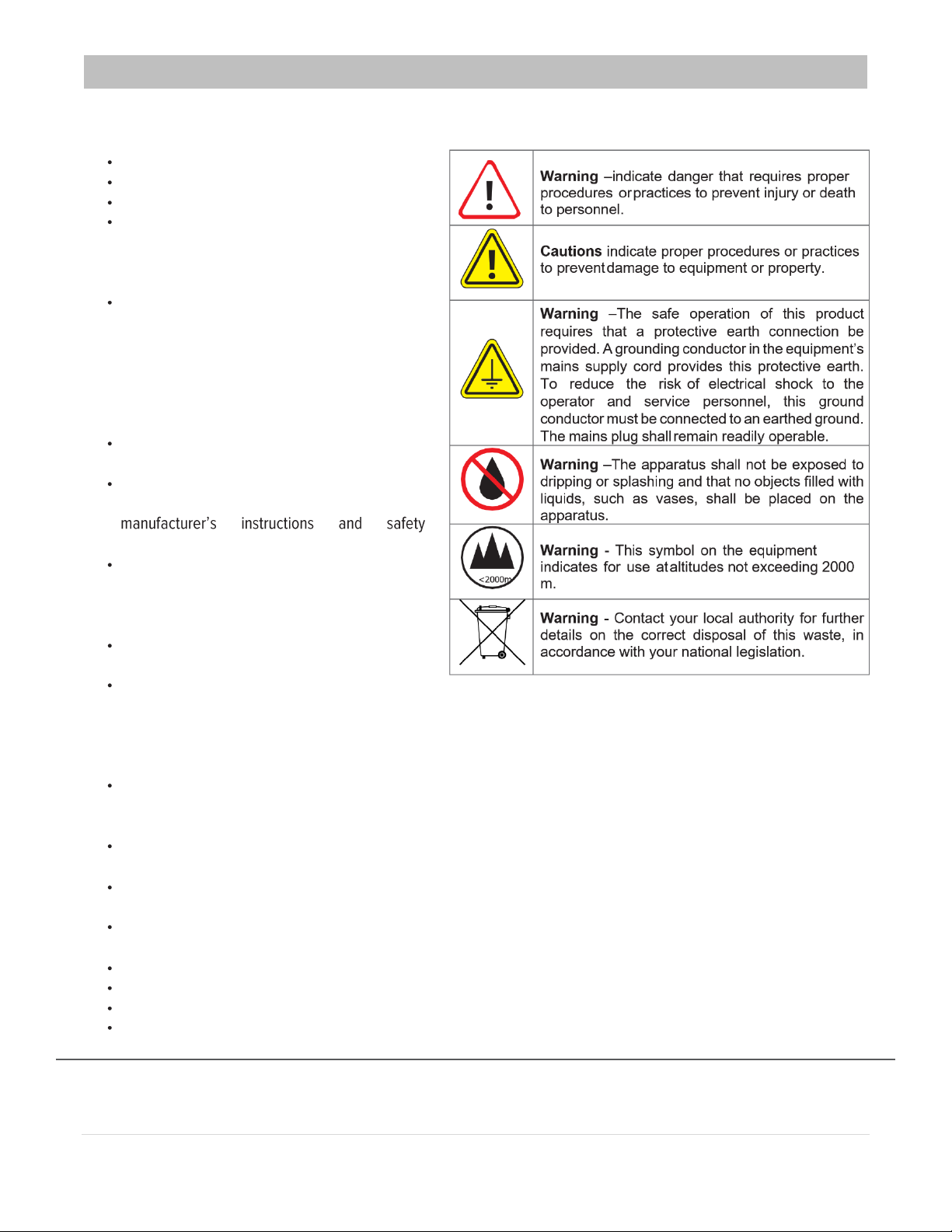
Throughoutthis manual, severalWarnings andCautions and Notesmay bepresentedto alert the user toimportant
safety oroperating information.
Always adhere to local building,safety and fire preventioncodes during the installationand operation of this product.
Use only power cords that were shipped with specified for this product and certified for the country of use.
Connect the unitonly to a power source withthe specified voltage rating.
Unless otherwise stated in the Installation Instructions, and in adherence to local Electrical Codes, MultiDyne®
Equipment should only be plugged into a standard 15-amp dedicated circuit.

4 | P a g e
Laser Safety Information
This unit is classified as a CLASS 1 LASER PRODUCT according to EN60825-1 (EU) andFDA 21CFR 1040.10 (USA). Class 1
laser products are considered safeand do not result in biological hazard if usedaccording to these instructions.
Warning –Use of controls, adjustments, or performance of procedures other than those specified herein may result in
hazardous radiation exposure.
Warning –Never look directly into the end of the optical fiber while either end of the system is operating.
Warning –Never clean an optical fiber connector on equipment or cable that is carrying light.
Warning –Always use dust caps on fiber optic connectors when cables are not connected. This will protect the connector from
damage and accidental exposure of a human eye to an operating laser.

5 | P a g e
OVERVIEW
1. Overview
The HoneyBadger (HB) is a multi-format transceiver that multiplexes a wide collection of broadcast
signal types onto 2 fibers. This includes SDI, analog and intercom audio, Gigabit Ethernet, Genlock
(sync), serial data (RS-232/422/485) and GPIO. This is all accomplished with a 4RU local box and a
5RU remote unit.
Video
There are 8 transmit and 8 receive (8x8) SDI signal paths available. For HD applications, the 3G model
supports SD/HD/3G-SDI. The HB can also support single-link 4K UHD with the 12G model, which
covers all SDI rates from SD- to 12G-SDI.
Audio
There are 8 transmit and 8 receive (8x8) balanced audio paths, with mic-level gain and phantom power
available on the 5RU end.
Intercom
Connect up to 4 RTS®or Clear-Com®intercoms with wet or dry power.
Ethernet
Two, fully independent 1GbE ports
Data/Tally/GPIO
Two RS-232/422/485 data paths, 2 GPIO, and 2 Tallys on multi-pin Phoenix connectors for easy
termination
Sync
Bi-/Tri-level genlock
Key Features
•Wide complement of signal types multiplex onto only 2 fibers
•Optional Fiber I/O includes ST, LC, SC, Lemo, and Neutrik OpticalCon Duo
•Full-sized connectors for fast setup
•Dual AC power supplies are supported to prevent dropouts.
•Anton-Bauer or V-mount Battery plate for emergency backup power

6 | P a g e
FEATURE DESCRIPTIONS
2. Feature Descriptions
2.1. Front Panel HB-DC-DBR (5RU)
A. Status Indicators –Intercom, Ethernet, Sync, Data/Tally, Audio
a. Intercom & Audio
Each LED is shared between 2 audio channels. For example, for Intercom (I-COM) IN “A”, the
LED will light when audio is detected on either channel 1 [CH1] or channel 2 [CH2].
b. Ethernet, Sync, and Data LEDs are lit when signal is detected. Detailed parameters are described
below in their respective sections.
c. LINK –LED indicates unit fiber link is up and running with remote end.
B. Status Indicators –SDI
Relative to the input and output BNCs, the data rate is indicated for each associated channel (SMPTE
rates only). For example, 1.5Gbps video will light the HD LED. Video going into the BNC is transmitted
(TX) to the remote end. Video received (RX) from remote unit is output from BNC.
C. Intercoms
See Section 3.1 for details on the level meters and operation of Intercom modules.
D. SDI I/O
IN 1–8 are transmitted to remote end.
OUT 1–8 are received from remote end.

7 | P a g e
FEATURE DESCRIPTIONS
E. Sync
Output from the Local end. The Sync Card can transport a video reference signal in formats that include
NTSC, PAL, and HD Tri-Level. Only the sync portion of the signal is transported across a fiber link, all
video and color information are stripped from the signal.
HD SYNC supported formats:
NTSC, PAL, 1080p30, 1080p29.97, 1080p25, 1080p24, 1080p23.98, 1080psf24, 1080psf23.98, 1080i60, 1080i59.94,
1080i50, 720p60, 720p59.94, 720p50, 1080p60, 1080p59.94, 1080p50
F. Data, GPIO, & Tally I/O
Data 1 and Data 2 each support one bi-directional Tally, one GPIO Bidirectional Channel, and two Data
Channels transport up to 3Mbps. The LEDs in the front will turn on showing the data paths are active. The
HoneyBadger is built with 422 selected as the default mode. RS-232 and RS-422 operate in full-duplex
mode. RS-485 operates in half duplex and is available by contacting MultiDyne.
G. Ethernet
Each Ethernet port supports rates of 10/100/1000 Mbps. When a link is established between two units,
the green LED on the front panel for respective channel will turn on. Then as each port senses data
activity the LEDs will flicker.
H. MIC/Line Inputs 1–8
See Section 3.2 for details on the MIC/Line Input operation and their indicators.
I. Audio Outputs 1–8
Industry standard, balanced XLR line-level audio output received from remote unit.

8 | P a g e
FEATURE DESCRIPTIONS
2.2. Front Panel HB-DC-DBL (4RU)
Since both boxes are mirror images of each other, only the differences from 5RU are
shown here. See Section 2.1 for full panel descriptions.
A. Intercom Matrix
Patch balanced audio to interface with Matrix frames. Section 2.4.1 has detailed pinouts.
B. Sync
Input sent to remote end. Supported rates mentioned in Section 2.1.E
C. Audio I/O 1–8
Line-level balanced audio

9 | P a g e
FEATURE DESCRIPTIONS
2.3. Rear Panel (Both Models)
A. UFP
Universal Fiber Plate for fiber I/O interface. Fiber options are chosen at time of order. See
Section 6 for all available fiber types.
B. AC Power supplies + cover
One power supply is installed by default. For redundnacy in case of supply failure, a 2nd unit can
be installed. See the Accessories section for part numbers.
C. Battery Plate
Battery support for emergency power backup. Battery options are chosen at time of order, AB
for Anton Bauer and Vfor V-mount type.
The 3G HB consumes around 5A @ 14.7V [no Intercom beltpacks]. Therefore a 140Wh battery,
for example, should run the unit for a little less than 2 hours.

10 | P a g e
FEATURE DESCRIPTIONS
2.4. Pinouts
2.4.1. Intercom Matrix
Pin
Function
1
x
2
x
3
OUT+
4
IN-
5
OUT-
6
IN+
7
x
8
x
Diagram

12 | P a g e
FEATURE DESCRIPTIONS
2.4.4. GPIO & Tally
Pin
Function
1
GP Input
2
GP Output
3
Tally In
4
Tally Out
5
Ground
Diagram
2.4.5. Audio
Industry standard for XLR balanced audio
Pin
Function
1
Ground
2
Balanced Audio +
3
Balanced Audio -

13 | P a g e
OPERATION
3. Operation
3.1. Intercom (4x) [HB-DC-DBROnly]
The Intercom units provide a means to interface between two channels of 2-wire party-line intercom
audio and two channels of 4-Wire analog line-level signals. The unit can perform auto-nulling for each
channel with the push of a button. In addition, each of the 4-Wire input and output channel levels are
monitored and displayed on front panel VU meters.
With the flip of a switch the unit can be a +28VDC party-line voltage power source while providing the
200-ohm intercom audio termination on both channels. If so desired, the party-line source and
termination can be removed by just flipping the switch back. The unit can also be configured to work
with either RTS party-line or Clear Com party-line equipment with the flip of a front panel control switch.
This switch adjusts the output gain between the party line circuitry and the 4-wire line level circuitry
depending on which type of units one is interfacing with.
DIP
Switch
Off (Down)
On (Up)
1
DRY (No Power)
WET (+28V ON)
2
High Gain [RTS]
Low Gain [Clear-Com]
3
AUTO Terminate
WET Terminate
Switch 1
The Intercom can supply party-line power by moving the WET/DRY switch to the up position. With this
function enabled, the unit will provide +28 VDC to pin 2 of the XLR connector of the party-line ports.
When enabled, the CH1 WET LED will turn green. When selecting the WET mode, verify that the WET
LED is green. If red, it means there is a short or overload on the party-line, or the wetting circuitry within
the unit is defective. If the Intercom unit is to be connected to a party-line intercom system with an
existing power source, then the internal power supply within the Intercom board should be turned off.
This is accomplished by flipping the WET/DRY switch to DRY (down). When in DRY mode, the CH1
WET LED will go out. Pin 2 of the XLR connector will no longer provide +28VDC to the rest of the party-
line.

14 | P a g e
OPERATION
Switch 2
Set to RTS or Clear-Com mode.
To be compatible with RTS units, push the GAIN L/GAIN H switch UP; to be compatible with Clear Com
units push switch DOWN.
This switch adjusts the gain needed to interface between the 4-wire to 2-wire signals and it also adjusts
the gain from the 2-wire to 4-wire signals. It increases the gain going from a Clear Com connected 2-
wire unit to the 4-wire side of the interface to compensate for the lower 2-wire operating voltages of the
Clear Com units as compared to RTS units. The RTS units operate at a higher voltage on the party-line
side and thus require less gain when translating from 2-wire to 4-wire signals. When the signal
originates from the 4-wire side and translates over to the 2-wire side the gains are opposite. Less gain
is applied to a 4-wire input as it translates to the 2-wire side of the interface with when a Clear Com unit
is present on the party-line connection as opposed to a RTS unit.
Switch 3
The Intercom can be set to the AUTOTERM mode by pushing the WET TERM/AUT TERM switch
down. When this selection is chosen, the unit will look at both party-line channels to see if they contain
the +28 VDC wetting voltage. For channel 1 the unit’s internal circuitry will remove the internal 200-ohm
terminating resistor if the unit is sourcing the +28 VDC or if it is externally wetted. For Ch2, it will
remove the 200-ohm only if the channel is externally wetted. (Ch2 cannot be internally wetted). If the
WET TERM is selected, then if the Intercom is providing the +28 VDC (WET/DRY switch set to WET),
both channels will be terminated. If the Intercom is not providing the +28 VDC (WET/DRY switch set to
DRY) then the terminations on both channels are removed.
NULL Toggle Switch (Ch1 & Ch2)
Auto nulling is done to achieve maximum return loss between the 4-wire input and the 4-wire output
channels. Auto nulling can be and should be done whenever there’s been changes made to the party-
line connections.
To auto null Channel 1, slide the NULL switch to the left momentarily and release. Observe that the null
CH1 status LED glows orange while the nulling process is taking place. The Intercom will also produce
a 24khz Mic Kill tone. RTS compatible belt packs will respond to this tone and automatically kill the mic
input. If you have another type of belt pack, be sure to turn off the mic input or the null will be poor. The
process should last about 20 seconds after which time the LED will turn green if successful or red if a
null was not able to be obtained. Wait for the auto nulling process to complete on one channel before
attempting to do it on the other channel. Repeat these steps for nulling Channel 2 by momentarily
sliding the switch to the right while observing the CH2 LED alongside it. During the auto nulling process
there will be tones of 1kHz, 300Hz, 3kHz and 1kHz again on each of the party line channels.
After the nulling process is complete, you will need to re-enable your mic inputs. If two or more
Intercom units are used as part of the 2-Wire system, they should be nulled to prevent an audio
feedback path that may cause an audio oscillation. This is evidenced by the VU LEDs being maxed, as
well as an audio squeal, howling or whistle. Once the units are nulled, this should go away. But it can
also return if one of the belt packs or other loads are changed or disconnected from one or both ends.
Then the oscillation will return since the load that the intercom has been nulled for is suddenly gone,

15 | P a g e
OPERATION
and the resulting lack audio return loss will result in feedback. Note that if the party line has been
altered after a null has been done, the status LEDs will not update on their own. They do not monitor
status on a continuous basis. They only reflect the result of the last nulling procedure, so it will be
necessary to perform the nulling procedure again. This is commonplace in the industry, as it is
impossible to measure the depth of the null on a continuous basis without asserting mic kill and
injecting tones.
Level Meters
The Intercom unit contains four, 5-segment LED VU meters on the front panel. The first set displays the
4-wire input levels for Channel 1 as well as the 4-wire output levels for Channel 1. The second set of
VU meters display the input and output levels associated with Channel 2. The nominal 4-wire input
level for either version of Intercom is +4dBu which should correspond to the lower four LEDs for an
input channel turning green with the top LED off (0 LED represents 4dBu). If the input is 6 dB or more
over the nominal input value, then the top LED will light yellow indicating clipping could be on the verge
of occurring. The output VU meters function in the same manner as the input meters. To maintain
accuracy of the meters, the system should always be re-nulled if any of the party-line connections are
changed.
Summary of Internal Termination States vs. Mode Selection
External DC (WET)
Y/N
Unit Mode
Wet/Dry
Auto Term
On/Off
Channel 1 Int.
Termination On
Y/N
Channel 2 Int.
Termination On
Y/N
N
DRY
OFF
N
N
N
DRY
ON
Y
Y
Y
DRY
OFF
N
N
Y
DRY
ON
N
Y
N
WET
OFF
Y
Y
N
WET
ON
Y
N

16 | P a g e
OPERATION
3.2. MIC/Line Inputs (8x) [HB-DC-DBROnly]
The MIC level inputs contain microphone preamplifiers intended for use with low-level microphones or
line-level audio sources. It features adjustable input gain and impedance settings, LED metering, and
individual 48V/12V phantom power (or A-B powered) for each input.
The display area has 2 parts: the VU meter itself, and the two blocks for gain control next to it. The top
block displays the mic gain and the bottom block the line gain.
Along the bottom are the control switches for the mic phantom power, level gain, and to switch between
Mic and Line level for both channels, respectively. The VU meter is set to show a relative value that can
be set to US broadcast audio level of +24dBu FS, EBU R68 of +18dBuFS and consumer level of
+12dBu FS.
12V/48V PH Phantom Power
The phantom toggle switch has 3 phantom voltage modes. By default, all the phantoms will be turned
off or it will be in the previously selected mode before the unit was turned off. The phantom voltage
mode will turn on the direction the toggle switch is pushed. To turn the 12T power on, push the toggle
switch UP. To turn it off push it UP again, or down.
When phantom power is on, the corresponding LED will be lit green. The operation of the switch for
48V phantom is the same, but when the toggle switch is pushed down. The maximum recommended
current rating is 5mA for the microphone connected to each channel input. If the microphone connected
to it draws more current than 5mA the LEDs will turn red. If there is any problem with the phantom
power the LED will turn red. Phantom voltages will not turn on when operated in line mode [L] to avoid
damage to the systems connected to the inputs.
WARNING: The 48 V phantom power biases both pin2 and pin3 to 48V (referenced to pin 1). But the
12T power measures 12V across pin 2 and pin 3.

17 | P a g e
OPERATION
GAIN
The gain is adjusted by toggling the gain switch up or down in the front panel. Push it up to increase the
gain and down to reduce the gain. The gain is displayed in the two gain LED blocks for either line or
microphone as selected by toggling the M-L switch.
There are 9 total gain adjustment steps in Line and Mic modes:
Line mode: -4dB, -3dB, -2dB, -1dB, 0dB, +1dB, +2dB, +3dB, +4dB.
Mic mode: +10dB, +15dB, +20dB, +25dB, +30dB, +35dB, +40dB, +45dB, +50dB
The gain is incremented by 1dB in Line mode and 5dB in Mic mode. For both line and mic modes, the
gain positions which are intermediate to those indicated on the gain LED bar are indicated by lighting
two adjacent LEDs together.
Example: In line mode, when the gain is increased to -3dB from -4dB by toggling the switch up. This
will be indicated by lighting up the LEDs corresponding to -4dB and -2dB. If the gain is increased
again, then the LED -2dB position will light up alone. The LEDs for the gain on mic mode work
similarly.
•Default max audio levels are +24dBu. Contact MultiDyne for other custom levels, e.g., +18.
•Input impedance can also be selected if needed (2.4k, 660 ohm). Contact MultiDyne.

18 | P a g e
ACCESSORIES / FIELD-REPLACEABLE UNITS
4. Accessories / Field-Replaceable Units
Description
Part Number
Redundant/Replacement External Power Supply
OEM-00010
Pull Handle 4RU
HWR-00087
Pull Handle 5RU
HWR-00093
Fan Assembly (Single)
80-0123-004

19 | P a g e
ACCESSORIES / FIELD-REPLACEABLE UNITS
4.1 Fiber Plate Options
The 3-digit suffix of the top-level part number indicates the fiber connector type.
-LC2
LC/UPC
-SC2
SC/UPC
-ST2
ST/UPC
-OC2
Neutrik®opticalCON®Duo

20 | P a g e
SPECIFICATIONS
5. Specifications
5.1 HB-DBL 4RU Unit Dimensions & Weight
WEIGHT: ~38 lbs. [17kg]
Table of contents
Other MultiDyne Recording Equipment manuals
Popular Recording Equipment manuals by other brands

IMG STAGE LINE
IMG STAGE LINE DSM-26LAN instruction manual

IMG STAGE LINE
IMG STAGE LINE MFX-16M instruction manual

Spy Tec
Spy Tec LR32BOX user manual

iCON Pro Audio
iCON Pro Audio PLATFORM U32 user manual

Sunfire
Sunfire THEATER GRAND PROCESSOR II user manual

IMG STAGE LINE
IMG STAGE LINE DELTA-160 instruction manual