Multilink SR-2 User manual

SR Series
Selective Ring Processor
Online Operating
Instructions
www.multi-link.net

REAR
.
/
3
4 5
1) Barge-In Protection Switch 2) Power Indicator Light 3) Device Ports
4) Telephone Line Connector Port 5) 12 Volt
AC
Power Input
FRONT
REAR
456
1) Barge-In Protection Switch 2) Device Port Select Switch 3) Power Indicator Light
4) Device Ports 5) Telephone Line Connector 6) 12 Volt
AC
Power Input

Contents
1
2
3
4
5
6
7
8
Introduction/
How the SR Cal1 Processor Works
.....................
.2
Features
and Applications
.................................
.4
Safety Instructions
.............................................
.6
Installation
..........................................................
.8
Single Line Installation
A. Simple
Plug
In
.................................................
11
B. Wiring Modifications
..........................................
12
C. Installation with Adapters
.....................................
14
D. Partial Supervision with One SR
...........................
15
E. Total Supervision with
Multiple
SR's
......................
17
Multiple Line Installation
A.
Before
a Key System
.........................................
18
B..
....................................
19
Commonly Asked Questions
............................
20
Appendix
Recommended Parts and Materiais
..........................
22
Technical Specifications
........................................
23
FCC Registration
..................................................
23
COPYRIGHT
©
1991
MULTI-LINK,
INC.
SR
series
1

Introduction/How the
SR Call Processor Works
1
Congratulations!
You
are now the owner of
the highest quality Selective Ring
Call
Processor
on
the market
-
The SR series.
We at Multi-Link value
you
as a customer and
have
provided
you
with this manual and a Warranty Registration Card.
Please read the manual carefully and be
sure
to
fill
out
all
the informatioti
requested
on
your warranty
card.
Should
you
need technical assistance,
please
call
our Technical Support department at 800-535-4651. Thank you
for selecting Multi-Link for your communications management needs.
A Word About the “Distinctive Ring
Service”
Your local telephone company has provided you with
an
inexpensive
“Distinctive Ring” service which
increases
your communications capability.
The service goes by different
names
depending
on
the telephone company
-Custom
Ringing
by U.S. West, Smart
Ring
by GTE, Ring
Master
by
Bell
South, Ring
Mate
by NYNEX,
Personalized
Ringing
by
Southwestern
Bell,
Call
Identification
Service
by Ameritech, Ident-a
Ring
by
Bell
Atlantic, etc. These services
all
work
in
the
same
manner. Two, and
sometimes three, different numbers can be requested from the phone
company. The numbers ring through a single line coming into the
business or residence and
each
number can be distinguished by the
pattern of the ring. These ring patterns are made up of various
combinations of ring bursts. Examples of the different ring patterns would
be:
Original Number
1 Regular Ring
Second Number 2 Short Rings
Third Number 3 Rings (Shorts and Longs)
2
SRSr

How
The SR Cal1 Processor
Works
The SR
Call
Processor counts the number of bursts
in
the ring pattern of
the telephone number
called.
It
then directs the
call
to one of the
numbered device ports at the rear of the unit. The device ports are output
jacks
that connect your phone devices (phones, MODEMs, FAX, answering
and dictation machines) to the SR
Call
Processor. When you
have
attached the phone devices you wish to use, the SR
Call
Processor routes
each
different ring pattern
(i.e.
telephone number) to a specific phone
device
without
ringing
other phones
on
the
same
line.
Example:
Ring Pattem
Port
Original Number
Device 1
Second Number
Device 2
Third Number
Device 3
Devices
Used
(examples)
Telephones
FAX
Computer Modem (SR3 only)
SR Series
3

Featuresand
Applications
There are
many
applications for your SR
Call
Processor
in
the home or
small
business. To
optimize the phone configuration that
is
best
for you, it
is
important to understand the
features
available from your SR
Call
Processor.
FEATURES
Exclusion
Feature
-
Both SR models
have
an
exclusion feature which
allows you to control line accessibility between your phone devices. This
feature can be activated by the protection switch labeled
“Barge-In”
on
the
front
panels
of the SR2 and SR3.
(See
inside front cover for end-panel
view).
1)
“Barge-In”
Protection
On
-
This setting enables you to protect
phone conversations and data transmissions from being interrupted by
other phone devices
on
the
same
line. When extensions are picked up
a busy
signal
will be heard.
2)
“Barge-In”
Protection Off
-
This setting allows you to answer any
incoming
call
from any extension
in
the home or business. In addition,
you can conference any
call
from any extension.
Surge Protection
-
This feature
is
standard for both the SR2 and SR3.
Harmful voltage spikes will be carried to the earth ground through the
SR’s
internal
surge suppression network when the SR
is
properly installed.
2/3
Port
Select
Switch [SR3 only]
-
This switch allows you to configure
your SR3 to
operate
with either 2 or 3 numbers. In the “2” position,
calls
will ring through to
Device
2
in
the shortest possible time. If you
have
3
numbers, the switch must be set
in
the
“3”
postion.
4
SR Series

APPLICATIONS
The advantage of
call
routing
is
to allow you the
capability of upgrading or modifying your
communications network as your needs
change.
Here
are a few
applications you may consider.
In The Home
-
With your SR
Call
Processor, you can now assign any
phone device
in
your home its own individual telephone number. Your
children, spouse or roommate can now
have
calls
routed to their personal
phones without ringing other phones
in
the house.
Home Office
-
In the home
office
application, it
is
important for
each
phone number to be routed without ringing other phone devices
in
the
house. The SR
Call
Processor will route the phone numbers you
have
assigned to your phone/office equipment to those particular devices.
You
may choose to
have
one number for your family phone, one for your
business phone, and if you
have
a FAX and/or MODEM, one for these. The
routing
process
is
completely invisible to the caller. No one will
ever
know
your business
is
operated out of your home.
Small
Business
-
Shared
office
space
by different businesses
is
predominant throughout the
US.
With the SR
Call
Processor, it
is
possible
for 3
small
businesses to share the the
same
single-line location without
having to share the
same
phone number. If you are a
small
business or
single residence
office
your FAX, modems, dictation and answering
machines may be assigned individual phone numbers.
SR Series
5

Safety
Instructions
Read These Instructions !!!
When using your SR Series
Call
Processor,
basic safety precautions should always be
followed to reduce the risk of
fire,
electric shock and injury to persons,
including the following:
1. Read and understand
all
instructions.
2. Follow
all
warnings and instructions marked
on
the product.
3. Unplug this product from the wall outlet
before
cleaning. Do not use
liquid cleaners or aerosol cleaners. Use a damp cloth for wiping off the
plastic cabinet.
4. Do not use or install this product near water, for example, near a bath
tub, wash bowl, kitchen sink, or laundry tub,
in
a wet basement, or near a
swimming pool.
5. Do not place this product
on
an
unstable
cart,
stand,
or
table. The
product may
fall,
causing serious
damage
to the product.
6. This product should never be placed near or
over
a radiator
or
heat
register.
7. This product should be operated only from the type of power source
indicated
on
the marking
label.
If you are not
sure
of the type of power
supply to your home, consult your dealer or local power company.
8. This product
is
equipped with a three wire grounding type plug having a
third (grounding)
pin.
This plug will only fit into a grounding type power
outlet. This
is
a safety feature. If you are unable to insert the plug into the
outlet, contact your electrician to
replace
your obsolete outlet. Do not
defeat the safety purpose of the grounding type plug.
9. Do not allow anything to rest
on
the power
cord.
Do not
locate
this
product where the cord will be abused by persons walking
on
it.
10. Do not overload
wall
outlets and extension cords as this can result
in
the risk of fire or electric shock.
6
SR Serles

11. Neverpush objects of
any
kind into this product
through cabinet slots as they may touch dangerous
V
voltage
points or short out parts that could result
in
a risk of fire or electric
shock. Never
spill
liquid of
any
kind
on
the product.
12. To reduce the risk of electric shock, do not disasemble this product, but
take it to a qualified serviceman when
some
service
or
repair work
is
required. Opening
or
removing covers may
expose
you to dangerous
voltages or other risks. Incorrect reassembly can cause electric shock when
the appliance
is
subsequently
used.
13. Unplug this product from the wall outlet and refer
servicing
to qualified
service personnel under the following conditions:
A) When the power supply
cord
or plug
is
damaged
or
frayed.
B) If liquid has
been
spilled into the product.
C) If the product has
been
exposed to rain or water.
D) If the product
does
not
operate
normally by following the operating
instructions. Adjust only those
controls
that are covered by the operating
instructions
because
improper adjustment of other controls may result
in
damage
and
will
often
require
extensive work by a qualified technician to
restore
the product to normal operation.
E) If the product has
been
dropped
or
the cabinet has
been
damaged.
F) If the product exhibits a distinct
change
in
performance.
14. Avoid using a telephone (other than a cordless type) during
an
electrical
storm. There may be a
remote
risk of electric shock from lightning.
15. Do not use the telephone to
report
a gas leak
in
the vicinity of the leak.
SAVE
THESE INSTRUCTIONS
!!!
INSTALLATION PRECAUTIONS
1. Never
install
telephone wiring during a lightning storm.
2. Never
install
telephone
jacks
in
wet locations unless the
jack
is
specially designed for wet locations.
3. Never touch uninsulated telephone wires or terminals unless the
telephone line has been disconnected at the network interface.
4. Use caution when installing or modifying telephone lines.
SR
Serles
7

Installation
Your SR
Call
Processor, when properly
installed and configured, can link together a
variety of telephones and data
communication products, including FAX machines, MODEMs, credit
authorization terminals and answering machines.
Proper Installation Is
Important!
You probably won’t be
able
to plug your SR
in
just anwhere and get the
desired
results.
Please read the following paragraphs to better understand
how to
install
your SR.
To understand the importance of proper installation and placement, think
of your SR
Call
Processor as a telephone “traffic
top”
that supervises
traffic through
an
intersection. Any telephones and data devices that are
attached THROUGH the SR can be allowed to ring, and allowed or denied
access
to the telephone line.
Just as a traffic
top
cannot control traffic that
does
not pass through his
intersection, your SR cannot properly control telephones and data devices
that are not connected THROUGH the SR.
There are three factors to consider when chosing
an
installation method.
They are:
1)
Which phones and data devices
require
ring
supervision?
Any data device that answers
calls
(FAX, MODEM, answering
machine,
etc.) should be connected THROUGH your SR. Phones
that may awaken you at night should
also
be connected through your
SR. Certain other phones may be left directly connected to the
telephone line if you
don't
need
barge-in
protection.
8
SR Serles

2)
3)
Do
I
need
barge-in
protection?
If
you use a data device (FAX, MODEM, etc), V
you should place the “BARGE-IN” switch
in
the “ON” position.For
your SR to properly provide barge-in protection, any telephone or
other device that could interrupt the
call
or data transfer must be
connected THROUGH the SR. If barge-in protection
is
not required
(for example,
in
a voice-only application at home), certain phones
may be attached directly to the telephone line.
Ease
and expense of changing my telephone wiring.
In most applications, a complete re-wire
is
not needed. Many homes
are wired
in
a way that allows
some
“tricks”
to make installation
easier and
less
expensive.
Several
methods of installation are described
in
the following pages.
Each
has
advantages
and
limitations.
If you
feel
uncomfortable at any point with the installation
procedures,
we
recommend that you contact your dealer for assistance.
You
may
also
want to contact your telephone company or
an
independent installer to
assist you with any wiring changes that may be necessary at your
site.
For Safety
Your telephone company has probably installed a
small
box called a
lightning
arrestor
near where the telephone line comes into your
building or home. Both the incoming line and the
wire(s)
servicing your
phones and equipment are attached to this box. Under no
circumstances should you disconnect or alter the wire going from this
box toward the telephone company. The only wires and connections
you should change are those going from this box toward your
equipment.
SR
Series
9

You will need to apply power to your SR with the
supplied AC adaptor. Be
sure
to pick
an
installation
V
location where a grounded
110VAC
power outlet
is
nearby. You will
also
want to set the switch(es)
on
your SR for your particular application
(See
inside front
cover).
Initial
Check
Out
Please
check
the box and make
sure
you
have:
-either
an
SR2 or SR3 Selective Ring
Call
Processor
-a 12 VAC
Class
2 power source
-one silver modular line cord with
RJ-11
plugs
on
each
end.
-a Warranty Registration Card
If any of these items are missing, please
alert
the retailer from which you
purchased your SR
Call
Processor and
also
Multi-Link, Inc. at
1-606-885-6363.
The following installation examples describe the best ways to attach your
SR to either a single or multiple line telephone.
Each
is
described with a
rating of how the installation handles ring supervision, barge-in protection,
and ease/expense of installation!
NOTE:
All
installations described
on
the following pages
assume
that your
existing telephones will be rung by your primary number that generates a
single ring, and that your data equipment or
special
phones will be rung by
the additional numbers that
generate
multiple rings. If necessary, after
following these instructions, you may need to rearrange the number
assignments by rearranging the DEVICE
port
connections
on
your SR.
10
SR
Series

Single Line
Installation
A. Simple
Plug-In
(one
jack,
extensions)
Ring Supervision: Excellent
Barge-in Protection: Excellent
Install,
Ease/Expense
Excellent
To Telephone Co.
Central Office
This installation
will
only work if
you
have
only one
jack
with no extension
jacks!!!
If
you are fortunate enough to
have
this configuration
in
your home or
business, take your best friend out to dinner!
1) Simply unplug whatever
is
in
the
wall
jack and connect the “LINE” input
of your SR to the wall jack with the supplied line
cord.
2) Reattach your phone to DEVICE 1. Connect your data device to the
DEVICE 2 (and 3) ports with a line
cord.
SR
series
ll

B. Wiring Modifications
Ring Supervision:
Barge-in
Protection:
Install,
Ease/Expense
Excellent
V
Excellent
Difficult
Materials Needed: 2 modular
wall
jacks, 1
line
cord,
station wire (perhaps).
If
possible, this
is
the best way to
install
your SR when you
have
extension
telephones. Contact
an
installer if you need additional help.
1) Choose a suitable location for your SR. One good place to consider
is
near the point that the telephone line enters your home or building. Other
good places are where existing telephone jacks are located.
2) Disconnect the telephone company’s line from
all
of your existing jacks,
but
leave
the jacks still wired to
each
other. This needs to be done at a
point
BEFORE
the incoming line splits off to other extensions.
12
SR Series

3)
If
you disconnect the incoming
line
from a
jack,
label
the existing
jack
“TELEPHONES”. If you did not,
install
a
jack,
label
it “TELEPHONES”, and
connect the two wires going toward your phone equipment to the RED
and GREEN terminals of this new
jack.
4) Mount a modular jack* at the location of your SR and connect the
telephone company incoming line to the RED and GREEN terminals. It
may be necessary to run additional station wire* from the incoming
line.
Label
this jack “LINE”.
5) Connect the “LINE” input of your SR to the modular wall jack marked
“LINE” with the supplied line cord. Connect the wall jack marked
“TELEPHONES” to the DEVICE 1
jack
on
your SR with a line cord.
6) Attach any other telephones or data equipment to the other DEVICE
jacks
on
your SR.
7) If you need to attach
an
additional telephone to DEVICE 1 at the SR,
you can use a telephone line “Y” adapter* to allow you to plug two line
cords into the DEVICE 1
jack.
*
Refer to Recommended Parts and Materials Section, page 22.
SR Series
13

C. Installation with Adapters:
(only for use
in
homes where only one
line
is
used,
and
each
jack has four wires attached)
Ring Supervision: Excellent
Barge-in Protection: Excellent
Install,
Ease/Expense
Good
Materials
Needed: 1 two-line splitter for
each
existing wall
jack,
1
line
cord.
To Telephone
Co. Central
Office
l=
If your home has 4 or 6-wire cable to
each
wall
jack,
you can make your
installation look electronically like installation B by using
special
2-line (to
1-line) splitter
adapters*.
The adapters will utilize
an
unused pair of wires
in
your home to connect your telephones.
1) Choose a location where there
is
an
existing wall
jack
and where only
one phone or data device will be connected BY ITSELF to a DEVICE
jack.
You will
install
your SR at this location.
2) Unplug anything connected to this wall jack and plug the 2-line
adapter*
into the wall
jack.
3) (READ CAREFULLY) Connect the “LINE”
jack
of your SR to the
“LINE 1” side of the 2-line adapter with the supplied line
cord.
* Refer to Recommended
Parts
and Materials Section, page 22
Sectiuo2.
14
SR Series

4) Connect the “DEVICE 1” jack of your SR to the “LINE
2”
side of the
2-
line
adapter with a
line
cord.
5) Connect your data devices and/or other telephones to the DEVICE 2
(or 3)
jacks
on
your SR. These devices or phones will be rung by your
additional telephone number(s).
6) For
each
wall jack
in
your home, disconnect anything plugged into it.
Insert a 2-line adapter and re-connect the cord to the
,“LINE
2”
side
of the
adapter. If it
is
impractical to insert a 2-line adapter (for example, with a
wall-mount
telephone), convert this
jack
by:
a. Swapping the GREEN wire with the BLACK wire
b. Swapping the RED wire with the YELLOW wire
Then plug the phone
back
into the converted
jack.
D. Partial Supervision with One SR
Ring
Supervision: Fair
Barge-in
Protection: Sorry!
Install,
Ease/Expense
Excellent
If left to your own devices (ha, ha; bad
pun),
this
is
the installation that you
would probably stumble
upon,
and then
call
your dealer and complain that
your SR doesn’t work the way you wanted.
‘SR
‘GtSeriess
15

Partial Supervision
(cont)
To Telephone Co.
Central Office
In reality, this installation
is
fast, easy, and works great if you don’t need
barge-in protection and if you
don't
care
if your other phones ring
all
the
time. The best application
is
adding a FAX, MODEM, or answering
machine
on
the second number. The obvious drawback
is
that
even
if you
turn the barge-in switch “ON”
on
your SR, you can still interrupt a
call
with
your extension phones.
1) Choose a location with
an
existing wall jack to add your additional
equipment. Unplug any cord from the wall
jack.
Connect the “LINE”
jack
of your SR to the
wall
jack with the supplied line
cord.
2) Attach your equipment to the proper DEVICE jacks
on
your SR.
You
can also re-attach a telephone to DEVICE 1.
16
SR Series

E. Total Supervision
with Multiple
SR’s
Ring
Supervision
Barge-in Protection:
Install,
Ease/Expense
To Telephone Co.
Central Office
Excellent
Nope!
Excellent
If
total ring supervision
is
required for more than one phone, and barge-in
protection
is
not needed, buying additional SR
Call
Processors may be
less
expensive than changing your wiring, especially if your site
is
wired
in
a user-unfriendly way, or if your extensions are
in
other buildings.
For
EACH
location where you want the phone or data device to ring
on
only one number:
1) Unplug any cord attached to the
wall
jack.
Connect the “LINE”
jack
of
your SR to the
wall
jack
with the supplied line cord.
2) Reconnect your phone or data equipment to the proper DEVICE
jack
of
the SR, depending
on
which number you want it to respond to.
SR
SeriesSerles
17

Multiple Line
Installation
A.
Before
a Key System
Ring
Supervision:Excellent
Barge-in
Protection:
Excellent
Install,
Ease/Expense Good
TO KEY PHONES
You
can only
install
your SR
on
the CO* side of the KSU.
You
cannot
install
it
on
the station or extension
side.
1) Disconnect the desired line from the KSU.
2) Mount the SR
in
a convenient location near the KSU. Under two of the
feet
on
the SR are mounting slots.
3) At the
demarc,
install
an
RJ-11 if one
does
not exist.
Label
it “LINE”.
Attach the “LINE” jack of the SR to this RJ-11 with the supplied line
cord.
Shorten if desired.
*
Telephone company
18
SR
Serles
This manual suits for next models
1
Table of contents
Other Multilink Computer Hardware manuals
Multilink
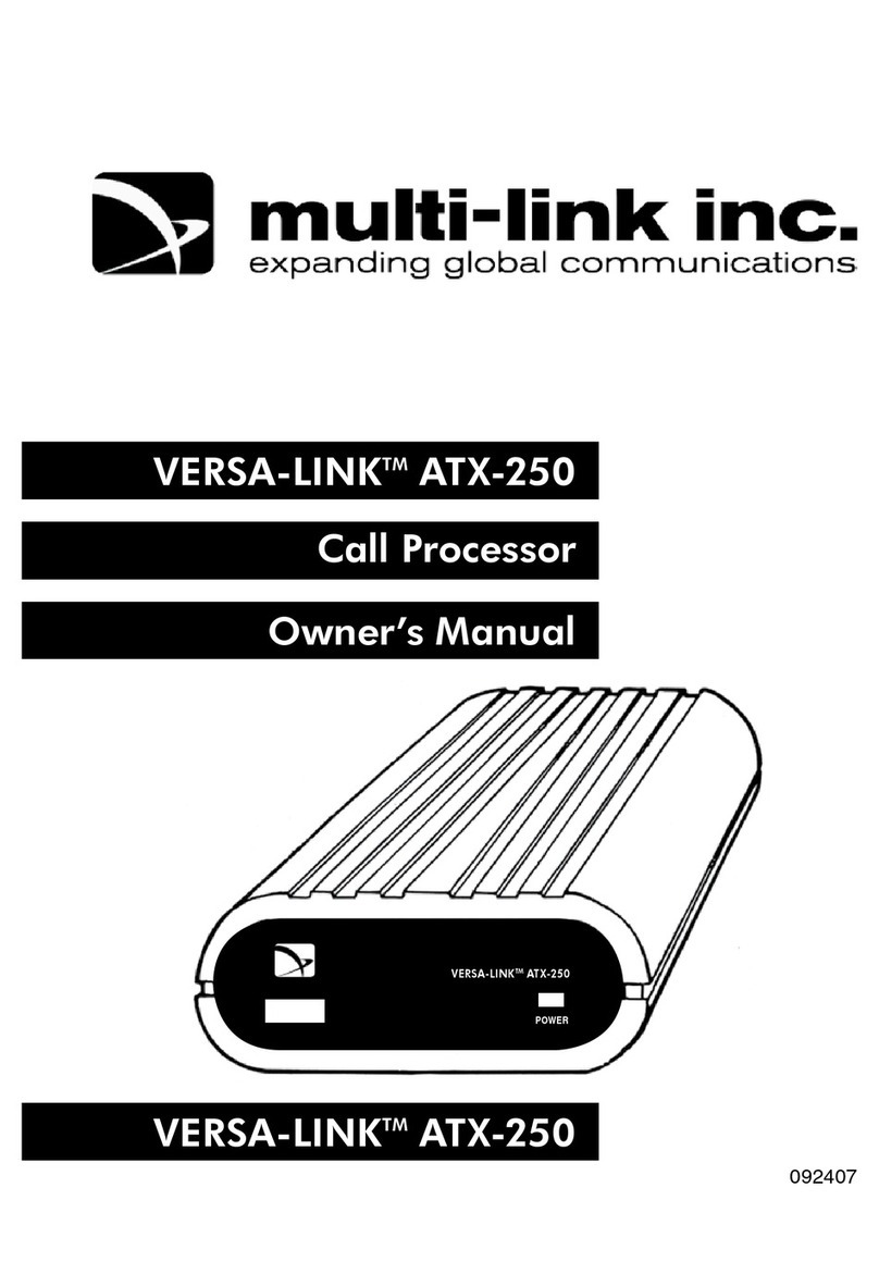
Multilink VERSA-LINKTM ATX-250 User manual

Multilink
Multilink Versa-Link ATX-300 User manual

Multilink
Multilink VERSA-LINKTM ATX-250 User manual

Multilink
Multilink The Stick Voice/Fax/Modem Call Processor Setup guide

Multilink
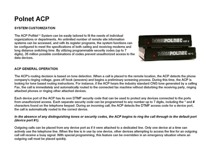
Multilink Polnet ACP-5 User manual
Multilink
Multilink Versa-Link ATX-300 Manual