Visit gomultilink.com for new product releases!
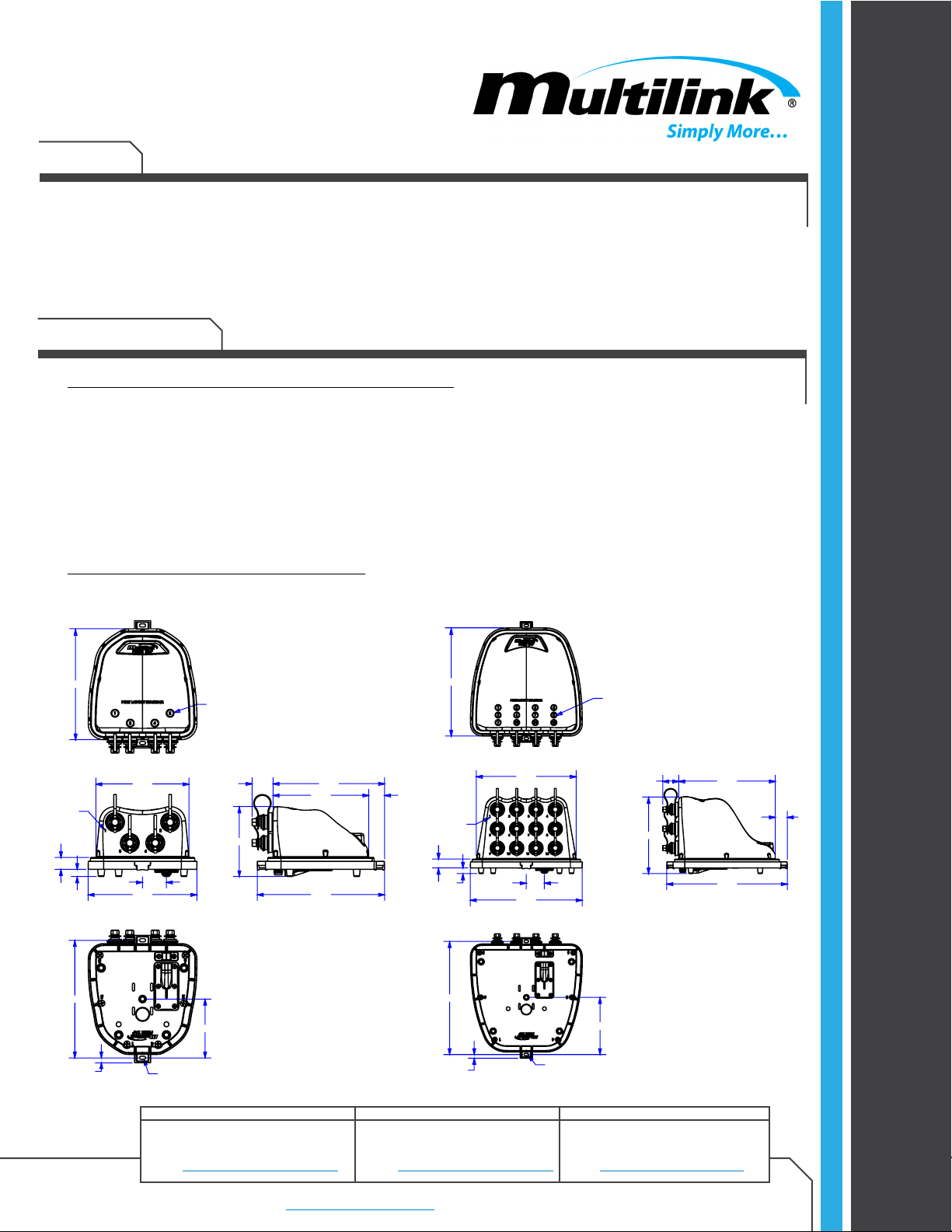
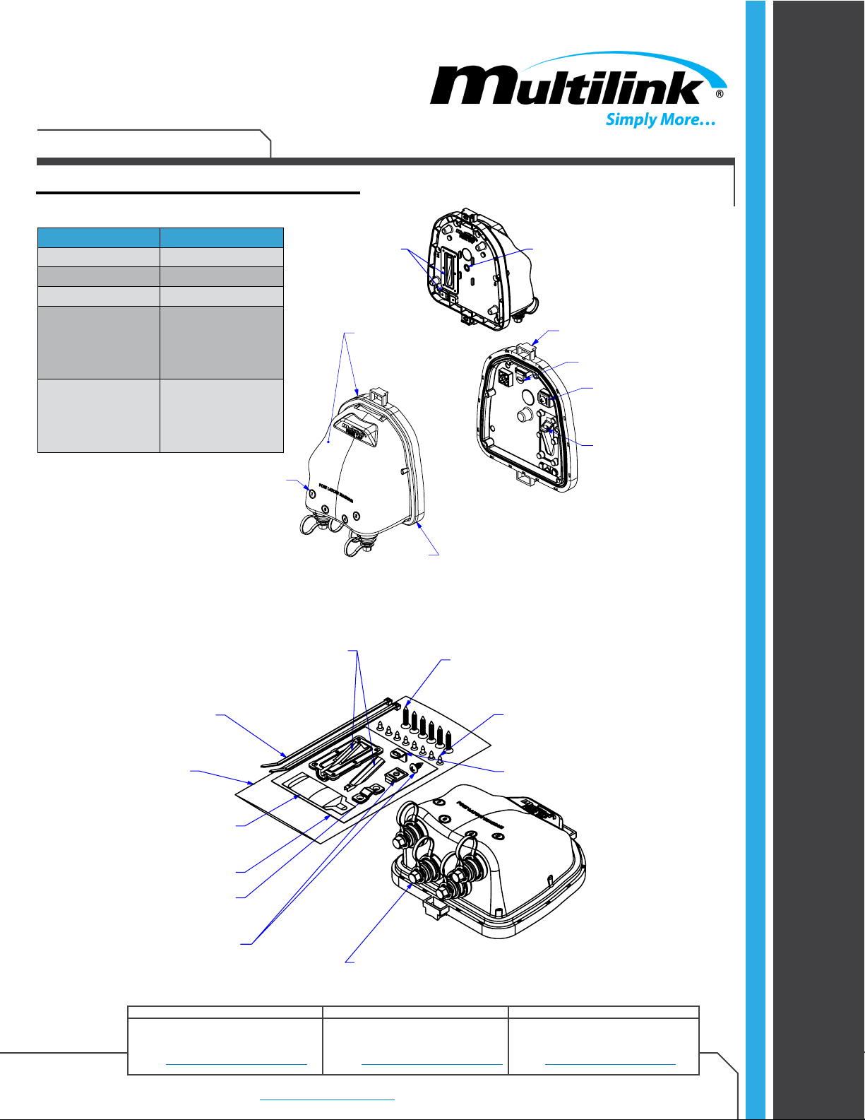
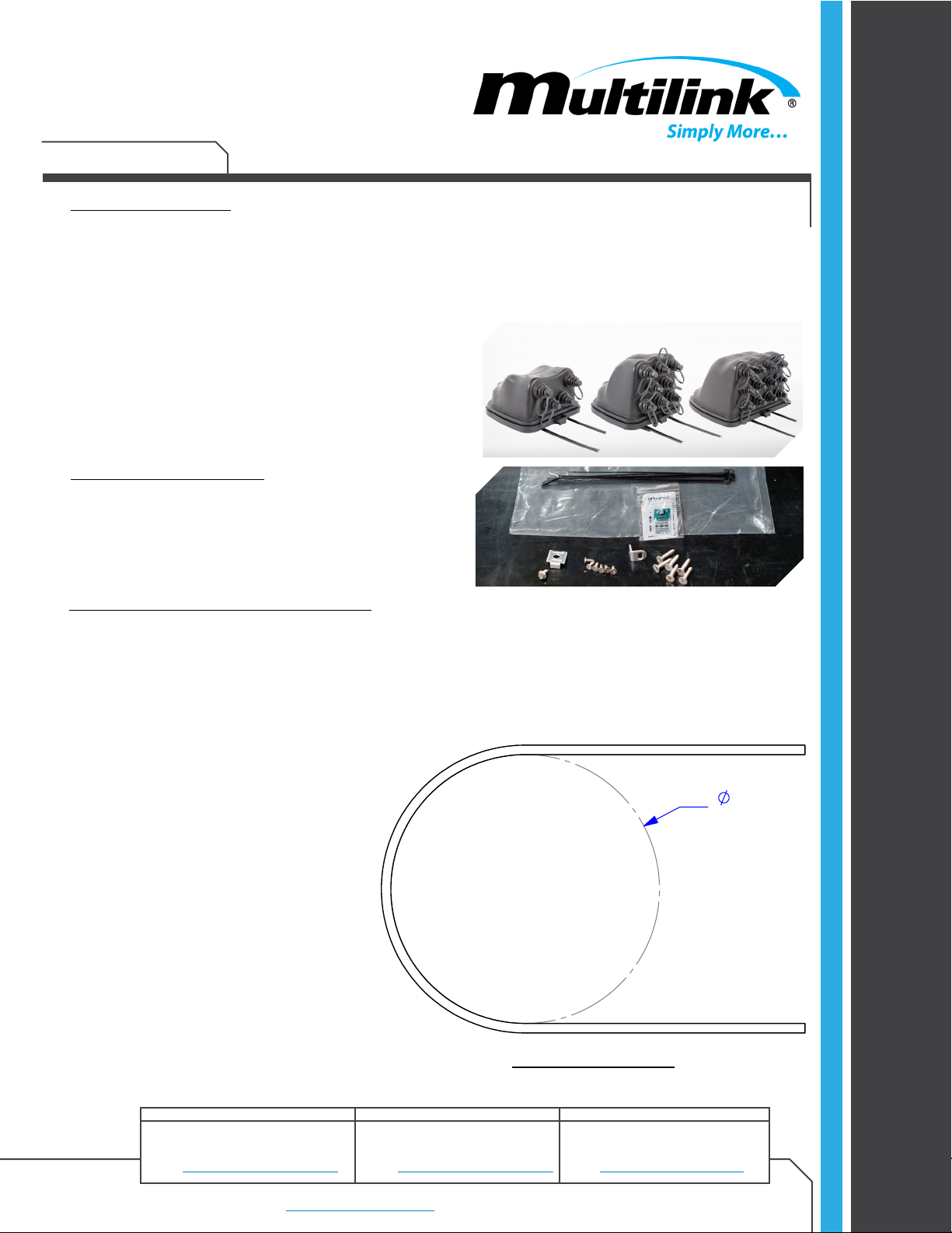
INSTALLATION
Copyright © 2021 Multilink Inc. All rights reserved • Specifications subject to change without notice • Rev. 6/14/2021 •
Contact Us |
North America
Tel: +1 440 366 6966
Fax: +1 440 366 6802
Email: engsupport@gomultilink.com
Tel: +1 440 366 6966
Fax: +1 440 366 6802
Email: engsupport@gomultilink.com
Tel: +1 440 366 6966
Fax: +1 440 366 6802
Email: lasupport@gomultilink.com
Europe, Middle East & Africa Latin & South America
Page 5
DocumentNo.020-306-20Install
3. General Warnings
3.1 Laser Light Warning
Never look directly into the end of a ber that may be carrying laser light. Laser light
can be invisible and may be harmful to your eyes. Viewing it directly may not cause pain;
therefore it will not cause blinking or the iris of the eye to close involuntarily as it does when
viewing bright light. Consequently, serious damage to the retina of the eye is possible.
Should accidental exposure of laser light be suspected, arrange an eye exam immediately.
3.2 Laser Light Magnication Warning
Do not use magniers in the presence of laser radiation. Diused laser light can cause
serious eye damage if focused with optical instruments.
3.3 Loose Fiber Warning
Cleaved or broken glass bers are very sharp and can pierce the skin easily. Keep your
work area clear of removed ber. Do not allow pieces of ber to stick to your clothing or fall
into the work area where they can cause injury later. Use tweezers to pick up broken/cut
pieces of ber and place on a piece of tape that has been set aside for this purpose.
3.4 Sharp Edge Warning
The wearing of cut-resistant safety gloves to protect your hands from sharp cutting
tools and the metal armoring of armored cable is strongly recommended. Use extreme care
when working with severed armor. There may be sharp edges where the armor is damaged.
Always cover the exposed/cut armor end with a wrap of black electrical tape. To minimize
the chance of injury from sharp-blade tools, always cut away from yourself and others.
Dispose of used blades and armor scrap properly.
3.5 Safety Glasses Warning
Use safety glasses while working is highly recommended to provide eye protection
from accidental injury when handling chemicals, cables or working with ber. Pieces of glass
ber are very sharp and have potential to damage the eye.
3.6 Electrical Shock Warning
Do not install telecommunications equipment or work with telephone wiring during
a lightning storm. Telephone lines can carry high voltages from lightning causing electrical
shock resulting in severe injury or death.
3.7 Fiber Damage Warning
Fiber Optic cable is highly sensitive to excessive pulling, bending and crushing.
Take care when bending the cables. Be sure not to pull too hard on the bers. Do not crush
the cable or allow it to kink. Doing any of these things may cause damage to the ber and
require it to be replaced.