Ormandy Rycroft Vari-E-Plate Installation and operation manual

Vari-E-Plate
Operating &
Maintenance Manual

Running Section 1
VERY IMPORTANT - PLEASE READ CAREFULLY
Safety Points 1.1 Page 1
Start Up 1.2 Page 1
Working Principles 1.3 Page 2
Installing Section 2
Sizing and Selection 2.1 Page 3
Installation 2.2 Page 5
Operation and Set Up 2.3 Page 6
Health Section 3
Maintenance 3.1 Page 14
Service 3.2 Page 14
Spares 3.3 Page 14
Information Section 4
Specication 4.1 Page 15
Maintenance
Access
Flow

1
• During operation, the unit may have very hot or cold surfaces.
• Thetemperatureprobeisinstalleddirectlyinthesecondaryow.Do
notremovewhenthesystemishot,fullofwaterorunderanypressure.
• Takecarewhenlifting.Onlyusethedesignatedliftingpoint.Useonly
certiedliftingequipmentcapableofliftingtheweight.Residualwater
may also be present and spillage could occur.
• NeverlifttheOrmandyRycroftVari-E-Platebyanyassociatedpipework
or pipe connections.
• Takecarewhenhandling,assomeedgesmaybesharp.
• Theequipmenthasdangerfromelectricity.Donotremovecoversor
allowanyexposedliveparts.Isolatebeforeworkingontheunit.
• The electrical and mechanical functionality must be considered prior
toconnectinganynonfactoryttedequipment.E.g.pumps,valves,
actuators etc.
• PowersupplyandcontrolsignalcablesMUST be segregated as far as is
reasonably practical.
• Shielded control cables must be used.
• Localauthorityregulationsmustbefollowedatalltimes.
• Ensurealloperationsarecarriedoutbysuitablytrained/qualied
personnel.
1.1 Safety Points
1. Running
Checks Complete (✓)
Check that electrical installation is complete.
Check that the mechanical installation is complete.
Checkthatthesystemhasbeenushed,butNOT through the plate pack and
that there are no leaks.
Check that any air has been eliminated from the system.
Checkthatvalvesareopenedintherequiredsequence.
1.2 Start Up

2
Theunitcomprisesofa2-portvalve,variablespeedprimarypump(SingleorDual),aplateheat
exchanger,secondarypumpandatemperaturesensorinthesecondaryow.Thetwoportvalveopens
andclosesinlinewiththesecondarydemand.Asthedemandrises,thesecondarytemperaturewill
starttofall,thuscausingthetwoportvalvetoopenandthevariablespeedpumptorampupand
delivertheincreaseddemandofprimarywater.
Thiscausesthesecondarytemperaturetorise,closingthetwowayvalveandslowingdownthe
variablespeedpump,thusreducingtheprimaryow.Ifthereisnodemand,thetwowayvalvewill
closeandtheprimarypumpwillstop,thusmaximisingenergysavings.TheOrmandyRycroft
Vari-E-Plateisusedaseitherastand-aloneinstantaneouswaterheaterasshownbelow.
SecondaryFlow
Temperature Gauge
Pressure Gauge
Expansion
Vessel
Expansion
Relief
Valve
Lockshield
Valve
Cold Feed
Non-Return
Valve
Circulating
Pump
Secondary
Shunt Pump
Drain
Pressure/Temp
ReliefValve
Temperature
Sensor
Commissioning
Valve
Drain
Plug
TwoWay
Valve
PrimaryReturn
Actuator
Primary Feed
Primary
Pump
1.3 Working Principle
Orinconjunctionwithabuffervesseltoformasemi-instantaneouswaterheater.
Temperature
Sensor
SecondaryFlow
Cold Feed
TwoWay
Valve
Primary
Pump
Primary Feed
Actuator
PrimaryReturn

3
TosizeastandaloneVari-E-Plate,usethefollowingdemandfactors.
Facility
Private
Hand
Basin
Public
Hand
Basin
Shower Bath Slop
Sink
Bar
Sink
Kitchen
Sink
Washing
Machine
Lab
Sink
Dish
Washer
Hospital 1 2 4 4 4 10 10 3 10
Residential
Hall & Hotel 1 2 4 4 4 12 10 10 10
School 0.5 3 10 -3 10 3 3 10
Sports Centre
/Barracks 0.5 2 10 -3 12 10 - - 10
Restaurant 0.5 4 - - 12 12 19 - - 10
University 0.5 3 10 -3-10 -3 10
Ofces 0.5 3 3 -3-10 -3 10
Factory 0.5 3 4 -3-10 -3 10
Apartments 1-4 4 3 -3 3 -2
Sizing Considerations
Carefulconsiderationmustbegiventothesizingofstandaloneinstantaneouswaterheaters.
Standarddemandunitsincorporateadegreeofdiversicationthatwouldbeinappropriatefor
continuous use applications. A more desirable method of sizing for continuous applications is to
completeaxturecountandallocateanappropriateowforeachtting.
ItshouldalsobenotedthatshowerdemandsforSchools,SportsCentresandUniversitiesshould
onlybeusedformediumtolargeinstallations.Refertoourdesigndepartmentforfurtherinformation.
Table 1
42singlepersonshowers 42x4 =168
55privatehandbasins 55x1 =55
9publichandbasins 9x2 =18
3slopsinks 3x4 =12
15baths 15x4 =60
Total Demand Units = 313
Theshowerfactorsarebased
upon intermittent use.
Where certain activities may result
inallshowersoperatingtogether,
please contact our sales
department for advice.
Example
FromTable1,a173bedHospitalwardwithshowers,handbasinsandsinks.
2.1 Sizing and Selection
2. Installing
ThecorrectlysizedVari-E-PlatecannowbeselectedfromTable2.
HT Breeze Model Maximum
Demand Units
MaxContinuousDuty
@60°C(litres/sec)
Boiler
Power(kw)
Min Secondary
Volume(litres)
GBPH50 23 0.50 105 75
GBPH100 70 1.00 209 125
GBPH150 130 1.50 313 150
GBPH200 210 2.00 418 200
GBPH250 320 2.50 522 250
GBPH300 480 3.00 627 300
GBPH350 640 3.50 732 350
GBPH400 820 4.00 836 400
Table 2

4
ThesesizesrepresentthestandardrangeofVari-E-Plateinstantaneouswaterheaters.Forlarger
requirementsforbothsingleandthreephase,pleasecontactourtechnicaldepartment.BothStandard
andSpecialdesignscanbeofferedtosuityourspecicrequirements.
To size a Vari-E-Plate and Buffer Vessel use the following maximum demand rates.
Facility
Private
Hand
Basin
Public
Hand
Basin
Shower Bath Slop
Sink
Bar
Sink
Kitchen
Sink
Washing
Machine
Lab
Sink
Dish
Washer
Load
Factor
Hospital 10 15 70 60 50 80 100 40 150 0.7
Residential
Hall & Hotels 10 15 50 50 50 100 80 100 150 0.5
School 5 20 180 40 80 40 40 150 0.8
Sports Centre
/Barracks 5 15 220 40 100 80 100 1
Restaurant 5 25 100 100 140 150 1
University 5 20 220 40 80 40 150 0.8
Ofces 5 10 180 40 40 40 100 1
Factory 5 20 120 50 80 40 100 1
Apartments 5 50 50 40 20 40 20 0.7
Table 3
42singlepersonshowers 42x70 =2940
55privatehandbasins 55x10 =550
9publichandbasins 9x15 =135
3slopsinks 3x50 =150
15baths 15x60 =900
Total Volume = 4675
Load Factor from Table 3 = 0.7
Total Demand Rate 4675 x 0.7 = 3273 litres/hr
Example
The Vari-E-Plate and Buffer Vessel combination, should be sized as follows:
TheBufferVesselCapacity=25%ofthetotalhourlydemand,thereforetherequiredstoragecapacity
=3273x0.25=818litres.TheneareststandardBufferVesselsizesare800and900litres.
Itisrecommendedtogoupinsizeandthereforea900litreBufferVesselshouldbeselected.
The Vari-E-plate can be selected as follows:
Continuoushourlydemand =3273litres
SpecicHeatCapacityofWater =4.187kj/kg,°C
ColdFeedTemperature =10°C
SecondaryFlowTemperature =60°C
Thereforetherequiredkwrating =3273x4.187x(60-10)
The nearest standard Vari-E-Plate is a GBPH100 which is rated at 209 kw
3600 = 190.3 kw

5
AVari-E-plateandBufferVesselcombinationisusedwhenwaterdemandisnotconstantbuthighow
frequentlyoccurs.Boilerpowerrequirementsarereducedbystoringhotwaterinthebuffervesselfor
peak demands.
TheVari-E-plateshouldalwaysbeinstalledwithasecondaryreturnlinecomingbackfromthesystem
andintothecoldfeedline,priortotheVari-E-plateorBufferVessel.Thiswillremovenuisancehigh
limittripping,duetotemperatureovershoot,whichwouldoccuriftheunitwasinstalledona‘deadend’
system,whenanoutletwasclosed.Toensurefullheatdissipation,thesecondaryvolumeshouldnot
belessthanthatshowninTable2.
For larger capacities contact the sales department for advice.
Foundation
TheOrmandyRycroftVari-E-Plate should be mounted on prepared foundations that are level.
Lifting
OneliftingholeisprovidedonthetopoftheVari-E-Platecontrolpanel. Avoid the use of chains, as
screwedconnectionsmaybedamagedbythelinks.
Caution: Never lift or move the Vari-E-Plate by its pipework or pipe connections.
Pipework
Makesurethatthepipeworkangesaresquareandcorrectlyspacedbeforeboltingup.Ensurethatthe
weightofthepipeworkistakenbyexternalsupportsandnotbytheOrmandyRycroftVari-E-Plate.
Allowancesshouldbemadeforexpansionofthepipeseitherbysuitablebendsorexiblejoints.
Tightenangeboltsinadiametricallyoppositesequence,notconsecutivelyroundeachange.
Connections
ThethreadedconnectionmaybesealedwithPTFEtape.Flangedconnectionsshouldbesealedwitha
suitable gasket and sealing agent.
Liquid Expansion
Changesinvolumewithtemperaturemustnotbeoverlooked.Thesystempressurewillrise
dramaticallyifthereisnowhereforwatertoexpand.Itisnotadvisabletouseareliefvalveasameans
ofreleasingtheexcesswater.
Ventedsystemsusetheatmosphericventasanexpansionpipewithdischargebackintothetank.
Unventedsystemsrequireaseparateexpansiontank.
Venting
Ventvalvesmustbettedatthehighestpointintheconnectingpipework,sothattheOrmandy
RycroftVari-E-Platecanbebledofairforinitialoperation.Itisessentialthattheoodedcantype
pumpmotorswhicharecommonlyusedforallOrmandyRycroftVari-E-Platepumps,arebledofairand
oodedbeforestarting.Seethepumpmanufacturer’sinstructions.
Filling
Beforellingthesystem check that the drain valve is closed and all air vents are open.
FlushoutthesystembeforeinstallingtheOrmandyRycroftVari-E-Plate,toremoveanyforeignmatter.
CloseanymanualairventsandruntheVari-E-Plate.Cracktheventstoreleaseair.
Caution: Do not ll the system too quickly, otherwise pockets of air may become trapped.
Do Not ush the system through the plate heat exchanger as this could result in the plates
becoming blocked or cause a loss in performance.
2.2 Installation

6
TheElectricalconnectionsarelocatedintheterminalcompartment.Adescriptionoftheterminalscan
be found on the inside of the terminal compartment cover.
Connectasinglephase230V50HzsupplytotheMainsInputterminals.Theratingplatewillhaveall
the information necessary to rate this supply.
Iftheunitistobecontrolledremotely,connecttheremotecontrolswitchorcontactstotheRemote
enableterminals.Iftheunitistobecontrolledlocally,talinkbetweentheseterminals.
DO NOT apply voltage to these terminals!
VoltagefreefaultrelaycontactsareprovidedforRemoteFaultIndication.
13 System Healthy Indicator
14 System Fault Indicator
15 Valve Position Bar Display
16 On/Off switch
1 Day/ModeDisplay
2 Time/AlarmDisplay
3 Temperature/ParameterDisplay
4 High Temperature Alarm Indicator
5 ResetPushButton
6 Step Left Push Button
7 Value Increase Push Button
8 Step Right Push Button
9 Value Decrease Push Button
10 Mode Select Push button
11 Pump Energised Indicator
12 Power On Indicator
2.3 Operation and Set Up
Electrical Connections
Terminal Block
1 2 3
4 5
6
7
8
9 10
11
12
13
15
14
16 ✓
✘
100
50
0
1
3
6
2
54
7
On/Off
Switch
KeytoOrmandyRycroftVari-E-Platecontrolsandindicators.
Mainsin230V
50HZ 1PH
Primary Pump
1230V
5AMax
Primary
Pump
2 Start
Primary
Pump
2 Fault
Primary
Pump
2 Control
Secondary
Pump1230V
5AMax
Secondary
Pump 2 230V
5A Max
AC
Signal
DC
Power
ValveActuator
LimitSwitch
Remote
Enable
VoltFree
Remote
Temp
Display
Remote
Temp
Setpoint
N
LN
L
N
L
31
Primary
Pump 1
Start
Primary
Pump 1
Fault
Primary
Pump 1
Control
+VE 0V N
L
+VE 0V +VE 0V
0/2-10V
24V
T
CC
+1 +1
4-20mA
N
L
78910 11 12 13 14 15 22 23 24 25 26 27 28 29 30
16 17 18 19 20 21 32 33 34 35 36 37 38 39 40 41 42 43 44 456
54
321
L N E
0-10V
Primary Pump
2230V
5AMax
0-10V
VoltFree
Fault
Contact
230V5A
AC1Max
High Limit
StatVolt
Free
4-20mA
v- v+
Type J
T/C
Sensor

7
Operation
TheVari-E-Plateisaself-containedunit,whichcontrolsuptotwoprimaryandtwosecondarypumps,
togetherwithatwo-portvalvetoprovidehotwater.Whenthesystemisttedwithtwoprimary
pumps,theyareoperatedonasharedduty-standbycyclewithautomaticchangeoveronpumpfailure.
a) Remote Switch or Building Management System Control
TheVari-E-PlatewillbeturnedonwhencontactsconnectedtotheRemoteEnableterminals are
closed.Thisallowstheusertocontrolthetimeofdaywhenhotwaterwillbeavailable.
When the contact is open the system is turned off.
b) Internal Time Clock Control
Forthisfunctiontowork,theTimeclockfunctionshouldbeturnedon(seeSetUp)andthe
RemoteEnableterminals should be linked.
UnderTimeclockcontrol,theVari-E-Platewillbeturnedonandoffatpresettimesoftheday.
Uptotwoonandtwoofftimescanbeprogrammedforeachdayoftheweek.
Thesystemcanbere-activatedafterithasautomaticallyswitchedoffbypressingthe
ValueIncrease(7)pushbutton.Eachpressofthispushbuttonwilladd30-minuteincrementsto
atotal,whichisshownintheTime/Alarmwindow.PressingtheValueDecrease(9) push button
willsubtract30-minuteincrementsfromthetotaltime.
Thetimevaluecountsdownandwhenthetimeshownhaselapsed,theunitwillrevertto
normal time clock operation.
c) Remote Switch and Internal Time Clock Control
Forthisfunctiontowork,theTimeclockfunctionshouldbeturnedon(seeSetUp)anda
remoteControlswitchshouldbeconnectedtotheRemoteEnableterminals.
UnderTimeclockcontrol,theVari-E-platewillbeautomaticallyturnedonandoffatpreset
timesoftheday.Uptotwoonandtwoofftimescanbeprogrammedforeachdayoftheweek.
When contacts connected to the RemoteEnableterminalsareopenedtheVari-E-Platewillbe
turned off.
When remotely enabled and the system has turned off under time clock control, it can be
re-activatedbypressingtheValueIncrease(7)pushbutton.Eachpressofthispushbuttonwill
add30-minuteincrementstoatotal,whichisshownintheTime/Alarmwindow.Pressingthe
ValueDecrease(9)pushbuttonwillsubtract30-minuteincrementsfromthetotaltime.
Thetimevaluecountsdownandwhenthetimeshownhaselapsed,theunitwillswitchoffand
reverttonormaltimeclockoperation.However,whenthesystemhasbeenturnedoffunder
remotecontrol,itcannotbere-activatedbypressingtheValueIncrease(7) push button.
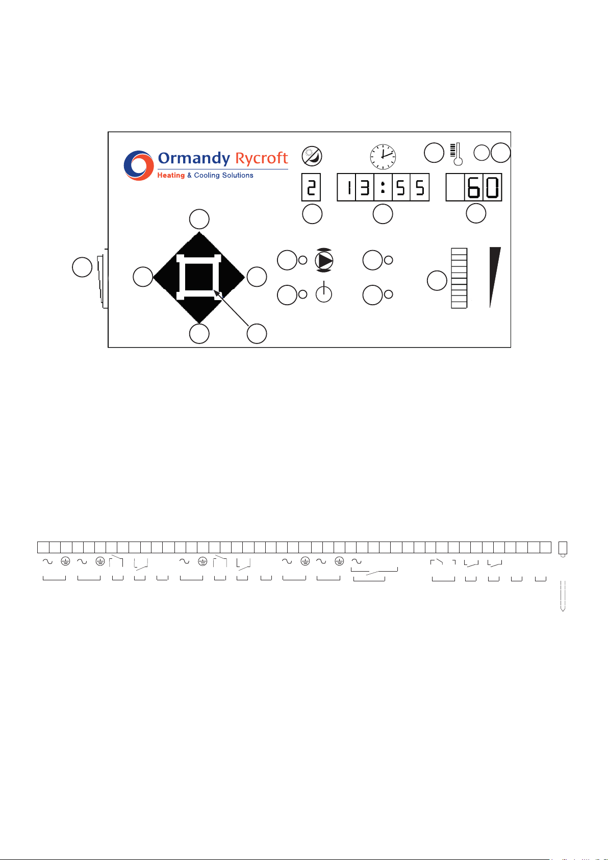
Switchonviaswitch(16)
Thefrontpanelwillilluminate.Afterafewsecondsofselfchecks,thedisplayswillsettletotheDay (1)
(Time-clockonly),Time (2) and Temperature (3).Thepumpswillstart(11),thevalvewillopen(15)
and the system healthy indicator (13)willilluminate.
Thestandardtemperaturesettingis60°Candtheunitwillruncontinuously.(24houroperation).
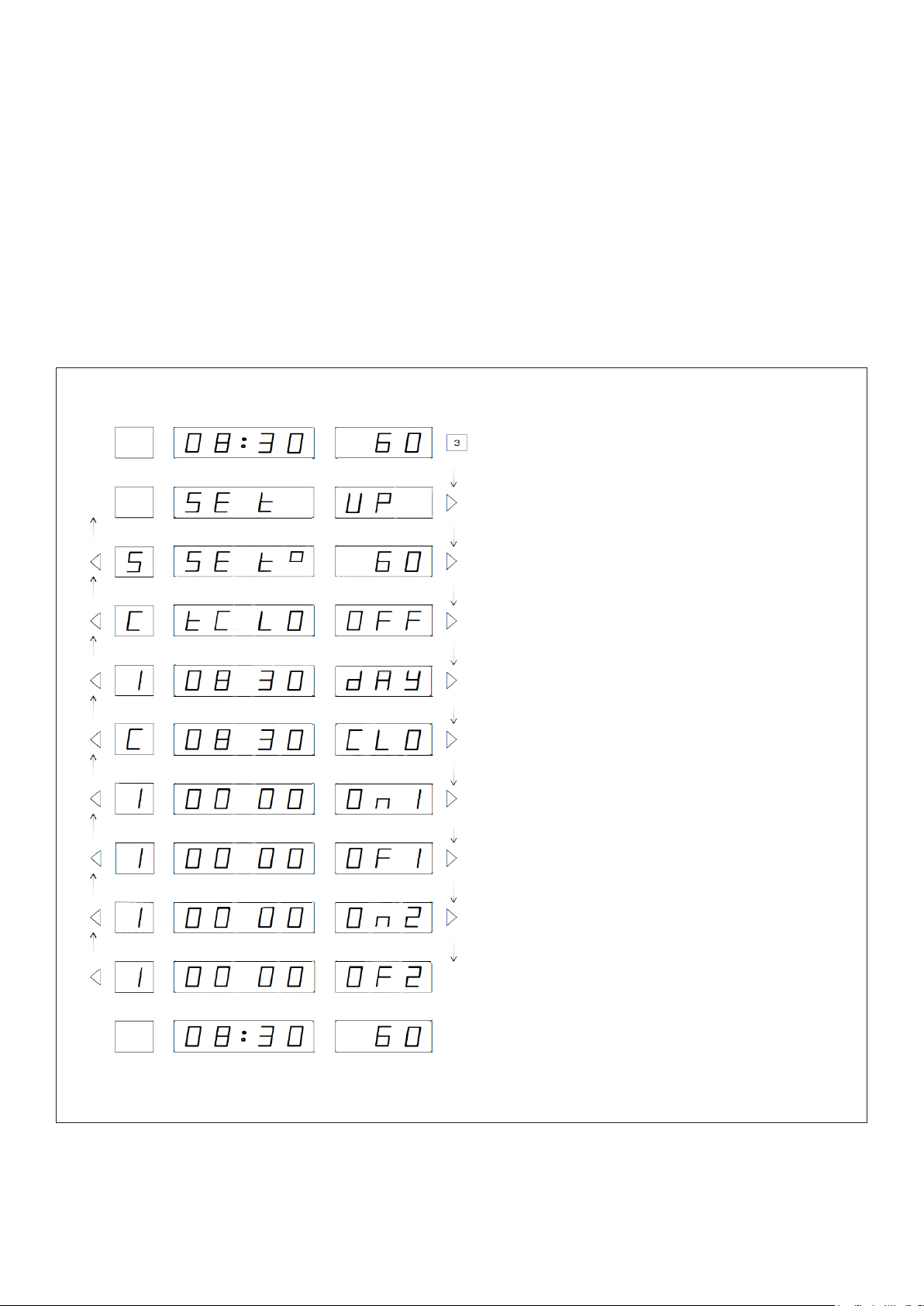
To change any of the default settings, refer to Figure 3
TheVari-E-Platecanbeenergisedbyitsowninternaltimeclockfunction,byaremoteswitchor
BuildingManagementSystemorbyacombinationofthetwo.

8
Set Up
TheVari-E-Platecontrolunitisfactoryprogrammedwithtemperatureandcontrolsettingsthatwillsuit
mostapplications.However,wewouldrecommendthattheunitiscommissionedtoensurecorrect
operationandmaximumefciency.ContactourServiceDepartmentfordetails.
Allthevaluesareadjustablesothatyoucancustomisetheunittoexactlymatchyoursystem.
The set up routine is entered by pressing and holding the Mode (10) push button for three seconds.
Press the StepRight(8) and Step left (6)pushbuttonstomoveforwardsandbackwardsthroughthe
sequence.PresstheValueIncrease(7) or ValueDecrease(9)pushbuttonstoalterthevalueshownin
the display. Press and hold the Mode (10)pushbuttonfor3secondstoexitthesetuproutine.
Figure 1 - Set Up Sequence
Press and hold for a minimum of 3 seconds
to enter Set Up routine.
Thesystemcontinuestocontrolwhenthecontrollerisinthesetuproutine,allowingadjustmentsto
bemadeonthey.
Press StepRighttomovetorstvalue.
Press ValueIncrease or Value Decrease
pushbuttonstoalterwatertemperature.
Press ValueIncrease to turn Time
clock function on or off.
Press ValueIncrease or ValueDecrease
to change Day number.
Press ValueIncrease or ValueDecrease
push buttons to change time. Press and
hold push button for rapid change.
Press ValueIncrease or ValueDecrease
push buttons to change the time of the
rsttimedonandoffperiod.Pressand
hold push button for rapid change.
Press ValueIncrease or ValueDecrease
push buttons to change the time of the
second timed on and off period. Press and
hold push button for rapid change.
Press StepRight push button to set the
on-offtimesforday2,day3,day4etc.
Press and hold ValueSelect push button
foraminimumof3secondstoexitSetUp
routine.

9
System Faults
Whenafaultsituationisdetected,theSystemFault(14)indicatorwillbelitandtheinternalFaultrelay
willbeenergised.Thenormaltimeandtemperaturedisplaywillbereplacedbyanalarmmessage.
ThemessagesandmeaningsareshowninFigure2below.Ifasystemfaultoccurswhenthecontroller
isinthesetuproutinetheSystemFault(14)indicatorwillbelitbutthedisplaywillnotbereplacedby
analarmmessage.ThealarmmessagecanbeviewedbyleavingtheSetUproutine.
First High temperature level detected.
SecondHightemperatureleveldetected-
buzzer sounds and the system is
automaticallyshutdown.
Lowtemperaturedetected.
PrimaryPumpNo1failure-iftwoprimary
pumpsarettedPrimaryPumpNo2will
be energised.
PrimaryPumpNo2failure-PrimaryPump
No1willbeenergised.
SecondaryPumpNo1(shunt)failure-
systemisautomaticallyshutdown.
SecondaryPumpNo2(re-circulation)
failure-systemisautomaticallyshutdown.
Thermo-couplefailure-thesystemis
automaticallyshutdown.
System has been remotely disabled
TheSecondHightemperaturelevelalarmwillautomaticallyshutthesystemdownandsounda
warningbuzzer.ThebuzzercanbesilencedbypressingtheReset(5) push button. When the fault has
beendiagnosedandcorrected,thesystemcanbere-activatedbypressingtheReset(5) push button
again.Thiscanonlybeperformedwhenthetemperatureshavereturnedtonearnormal.Alltheother
alarmswillautomaticallyresetwhentheproblemhasbeencorrected.Alarmsconstantlyre-occurring,
couldindicatethatthesystemhasbeenincorrectlycongured.
Advanced Set Up Routine
Thesystemissuppliedwithdefaultsettings,whichsuitmostapplications.Theadvancedsetupfeature
allowsInstallersandEngineerstotailorthesettingstosuitparticularinstallations.Thesystem
continuestocontrol,whenthecontrollerisintheadvancedsetuproutine,soresultsofadjustments
can be seen immediately. In addition manual control of the valve position is available.
Figure 2 - Alarm Messages

10
Set up routine is entered by simultaneously pressing and holding the Mode (10), Step Left (6) and Value
Decrease (9), Push buttons for a minimum of 3 seconds. Press the StepRight(8) and Step Left (6) push
buttonstomoveforwardsandbackwardsthroughthesequence.PresstheValueIncrease(7) or Value
Decrease (9)pushbuttonstoalterthevalueshowninthedisplay.PressandholdtheMode (10) push
buttonforaminimumof3secondstoexitthesetuproutine.
Press and hold for a minimum of 3 seconds to enter
Advanced Set Up routine.
Press StepRightpushbuttontomovetotherst
setting value.
Press ValueIncrease or ValueDecrease push
buttons to alter Proportional Band.
Press ValueIncrease or ValueDecrease push
buttons to alter Integral Time.
Press ValueIncrease or ValueDecrease push
buttons to alter Derivative time.
Press ValueIncrease or ValueDecrease push
buttons to alter First level High temperature limit.
Press ValueIncrease or ValueDecrease push
buttonstoalterLowTemperatureLimit.
Press ValueIncrease or ValueDecrease push
buttons to alter High Temperature Limit Time Delay.
Press ValueIncrease or ValueDecrease push
buttonstoalterLowerTemperatureLimitTimeDelay.
Press ValueIncrease or ValueDecrease push buttons
tovaryvalveposition.Figureshowspercentageopen.
See Manual Control.
Press ValueIncrease or ValueDecrease push
buttonstoalterPrimaryPumpover-runtime.
Press ValueIncrease or ValueDecrease push
buttonstoalterPrimaryPumpover-runtemperature.
Press ValueIncrease or ValueDecrease push
buttonstoalterSecondaryPumpover-runtime.
Press ValueIncrease or ValueDecrease push
buttonstoalterSecondaryPumpover-runtemperature.
Press ValueIncrease or ValueDecrease push buttons
toaltertheNightSet-back/Pasteurisationtemperature.
Press ValueIncrease or ValueDecrease push
buttonstoalterPrimaryPumpduty-standbytime.
Press and hold Mode push button for a minimum of 3
secondstoexitSetUproutine.
Figure 3 - Advanced Set Up

11
Night Set Back / Pasteurisation
WhentheDIPswitch(5)forNightset-back/Pasteurisationissettotheonpositionandtheunitisput
intostandbyviathetime-clock.Whenthepasteurisationtemperatureissettoabovethenormalset
temperature,thecontrollerwillassumepasteurisationandwillraisethetemperaturetothe
pasteurisation value for one hour, before returning to standby.
Alternativelywhenthesetback/pasteurisationvalueissettobelowthenormalsetvalue,thecontroller
willassumesetbackandwilllowerthetemperaturetothisvalueuntilthenextscheduledonperiod.
Manual Control
TheAdvancedSetUproutineallowstheengineertopositionthecontrolvalvemanually.Thisfeatureis
activewhilethissetupwindowisvisible.Thisfeatureisdisabledandcontrolrestoredtoautomaticby
pressing the Step Left (6), or StepRight(8) push buttons to display another parameter, or pressing and
holding the Mode (10),pushbuttontoexittheadvancedsetuproutine.
(Seepage6forkeytonumberreferences).
Remote Set Point Adjustment
Whena4-20mAsignalisconnectedtotheremoteinput,thesetpointcanbevariedbetween
20degC=4mAandl00degc=20mAattherateof5degreespermilliamp.
Itshouldbenotedthattheexternalcontrolsignalassumescontrolassoonasthemilliamplevelrises
above2mA.Consequentlyifthecontrollerlosesthissignal,itwillrevertbacktoit’sowninternalset
point.
DIP Switch Settings
ThephysicalcongurationofthesystemandtheNightSet-back/pasteurisationfunctionsare
programmedintothecontrollerbysettingthepositionofeightswitches.Theswitchesarelocatedon
thedisplayprintedcircuitboard.Tochangethepositionoftheseswitches:
1) Isolatethemainssupplytothecontroller.
2) Openthehingeddoor.
3) Removethefourxingscrewsandslidethecontrolfaciaoutoftheenclosuretakingcare
not to pull the connecting cable.
4) Turnthefaciaover.DIPswitchesarelocatedonthebottomedgeofthecircuitboard.
5) Changetheswitchpositionsasrequired(seetablebelow)
6) Replacefacia,closehingeddoorandswitchonthemainssupply.
1 2 3 4 5 6 7 8 Function
On No Operation
Off No Operation
On No Operation
Off No Operation
On FaultRelayOperatesDuringRemoteDisable
Off FaultRelay,NoOperationDuringRemoteDisable
On ValveOutput2-10V
Off ValveOutput0-10V
Off Night Setback OFF
On Night Setback ON
Off Off No Secondary Pumps Fitted
Off On 1SecondaryPumpFitted(SHUNT)
On Off 1SecondaryPumpFitted(RECIRC)
Off 1 Primary Pump Fitted
On 2 Primary Pumps Fitted
Thefollowingtableshowstheswitchcontrols.(Boldpositionsarefactorydefaultvalues).

12
Set Up:
Alternativesettingrecord(Date) ............. ............. .............
SetPoint =60 ............. ............. .............
TimeClock =Off ............. ............. .............
Day(Set) =1=Mon7=Sunday
Clock(Set) =Time
Day1ON1 =0000 ............. ............. .............
Day1OFF1 =0000 ............. ............. .............
Day1ON2 =0000 ............. ............. .............
Day1OFF2 =0000 ............. ............. .............
Day2ON1 =0000 ............. ............. .............
Day2OFF1 =0000 ............. ............. .............
Day2ON2 =0000 ............. ............. .............
Day2OFF2 =0000 ............. ............. .............
Day3ON1 =0000 ............. ............. .............
Day3OFF1 =0000 ............. ............. .............
Day3ON2 =0000 ............. ............. .............
Day3OFF2 =0000 ............. ............. .............
Day4ON1 =0000 ............. ............. .............
Day4OFF1 =0000 ............. ............. .............
Day4ON2 =0000 ............. ............. .............
Day4OFF2 =0000 ............. ............. .............
Day5ON1 =0000 ............. ............. .............
Day5OFF1 =0000 ............. ............. .............
Day5ON2 =0000 ............. ............. .............
Day5OFF2 =0000 ............. ............. .............
Day6ON1 =0000 ............. ............. .............
Day6OFF1 =0000 ............. ............. .............
Day6ON2 =0000 ............. ............. .............
Day6OFF2 =0000 ............. ............. .............
Day7ON1 =0000 ............. ............. .............
Day7OFF1 =0000 ............. ............. .............
Day7ON2 =0000 ............. ............. .............
Day7OFF2 =0000 ............. ............. .............
Alternativesettingrecord(Date)
............. ............. .............
ProportionalBand =60% ............. ............. .............
IntegralTime =4mins ............. ............. .............
DerivativeTime =Off ............. ............. .............
HighLimit =78°C............. ............. .............
LowTemperatureWarning =35°C............. ............. .............
HighTemperatureLimitTimeDelay=1min ............. ............. .............
LowTemperatureLimitTimeDelay =1min ............. ............. .............
ManualValveOperation =00% (Notpresetting)
Factory Default Settings
Set Set:

13
PrimaryPumpOverrunTime =5mins ............. ............. .............
PrimaryPumpOverrunTemperature =40°C............. ............. .............
SecondaryPumpOverrunTime =5mins ............. ............. .............
SecondaryPumpOverrunTemperature =40°C............. ............. .............
NightSet-back/PasteurisationTemperature =68°C............. ............. .............
PrimaryPumpDutyChangeoverTime =9hrs ............. ............. .............
By pressing the reset (5) and mode (10)buttonssimultaneouslyforafewseconds,thetimeclock
settingswillbereturnedtothefactorydefaultsettings.
By pressing the reset (5) and decrease (9)buttons,thecontrolandalarmparameterswillbereturned
to the factory default settings.

14
Wherepossible,adetailedinspectionoftheVari-E-Plateshouldbemadeaftertherstsixmonths.This
willprovideaninsightintofuturerequirementsforefcientmaintenance.IftheVari-E-plateiscleaned
andthereisnosignofcorrosion,itcanbesafelyassumedanannualinspectionwillbesufcientfor
future servicing. All electrical connections should be checked and tightened if necessary.
Caution:-Maintenanceshouldonlybeperformedbyqualiedpersonnelonly.Electricalworkshouldbe
carriedoutbyaqualiedelectricianinstrictconformancetothelatestrequirements.
InordertomaintaintheVari-E-Plateunityouwillrequireasaminimumthefollowingtoolkit:
• Set of Metric allen Keys up to M16
• Set of Metric spanners
• SetofScrewdrivers
• Apipewrenchtosuitamaximum50mmnominalpipesize.
• M16frictionratchetandM16deepringspanner(GBPH25toGBPH250)
Controller
ThecontrollerisrunviaanEPROMthatstoresallthechangestothetimeprogrammesandotherdata.
Aftertherstsixmonths,allconnectionsinthepanelshouldbecheckedandtightenedifnecessary.
Temperature Thermocouple
EnsurethattheThermocoupleconnectionsaresatisfactory.Refertothemanufacturer’sinstructions.
Control Valve and Actuator
Checkthatthevalvewillopenandclosebyusingthemanualfacilityonthecontroller.Electrical
connection should be checked at the actuator. The linkage should also be tightened to ensure good
mechanicalcontact.Refertothemanufacturer’sinstructions.
Hi-Limit / Control Valve and Actuator
Inadditiontotheabove,checkthatthevalveopensandclosesbyturningthepoweronandoff.
Electricalconnectionshouldbecheckedattheactuator.Thelinkageshouldalsobetightenedtoensure
goodmechanicalcontact.Refertothemanufacturer’sinstructions.
Primary Pump
Ensurethatthepumpisonthecorrectspeedsettingandthatwiringissecureatallterminals.
Plate Heat Exchanger
Aseriesofcontouredplateswithportsformaplatepackwithowchannels.Thehotwaterowsdown
alternatechannels,whilethecoldwaterowsupalternatechannels.Thiscreates100%counterow.
OrmandyRycroftEngineeringoffersafullandcomprehensiverangeofserviceandsupport.Thisen-
compassesthemaintenance,commissioningandrepairofgeneralwaterheatingequipment,including
heatexchangers,boilers,pressurisationunits,boostersetsandcaloriers.
AllVari-E-Platecomponentpartsareavailableasreplacement/spareitems.Pleasequoteasmuch
informationaspossibletoallowthesupplyofthecorrectpart(s).Serialnumber,photosetc.
3.1 Maintenance
3. Health
3.2 Service
3.3 Spares

15
Power Supply Requirements
Voltage:230Volts,50Hz.
Nominalcurrent:Maximum16Amps(PumpandDutydependant).
Inputs
Temperatureprobe:TypeJthermocouple(Grounded)viaa12bitA/D
converter(minimum0.1°Cresolution).Displayrange:0-250°C
Volt Free Contacts
Toenablefromremotesource(Time-clock,SCADA,BMS,boilercontrolsetc)
For connection of a supplementary high limit contact or thermostat as a second alarm.
PrimaryPump(s)faultcontact/s.
Signal
Remotesetpointadjustment.4-20mAScaled20°C-100°C.
Outputs
Pump Supply
• Twoprimarypumps(1Duty,1Standby)singlephase230v5AMaximum.
• Twosecondarypumps(1circulation,1shunt)singlephase230v5AMaximum.
Valve actuator supply
• 24v.a.c20VAMax
• Controlsignal2-10v/0-10.d.c0.1mA,Max.
• Theeffectivecontrolsettingrange0-85°C.
Volt Free Contacts
Changeover fault contact for remote alarm on fault, to SCADA, BMS, Annunciator etc.
Signal
Remoteindicationofprocessvariable.4-20mAscaled0°-100°C.
*NOTE: The volt free contact terminals must not have voltage applied to them.
4.1 Specification
4. Information

16
DuncombeRoad,
Bradford,EnglandBD89TB.
Telephone:+44(0)1274490911.Email:[email protected]
www.ormandygroup.com
Table of contents
Popular Industrial Equipment manuals by other brands

MICRO-AIR
MICRO-AIR OM600 Installation and operation manual

York
York P XU Series User's information, maintenance and service manual

Bühler technologies
Bühler technologies BWT Series Installation and operation instructions

Assa Abloy
Assa Abloy Corbin Russwin ED5602 Series installation instructions

Pilz
Pilz PSEN sl-0.5p 3.1 operating manual

ABB
ABB NEXUS-3 Series Installation and Wiring