AirBench RP Series Installation guide

AirBench™ RP Range
Operation and Maintenance
This Edition: 2 October 2018
AirBench Ltd, 14 Grange Farm Road, Colchester CO2 8JW
www.airbench.com
+44 (0) 1206 791191
© Copyright AirBench Ltd 2016
Page !of !1 19
AIRBENCH LTD

Cautions 4
Introduction 5
OVERVIEW!5
ABOUT AIRBENCH!5
ABOUT THIS DOCUMENT!5
Installation 6
GENERAL!6
ELECTRICAL!6
COMPRESSED AIR!6
ASSEMBLY OF ACCESSORIES!7
Commissioning 8
GENERAL!8
IN HOUSE COMMISSIONING!8
FUME EXTRACTION UNITS!8
Operation 9
PRIOR TO USE!9
GENERAL USE!9
FILTER CLEANING!9
Maintenance 11
FILTER CARE!11
SPARES !12
OTHER ROUTINE MAINTENANCE!13
Accessories 14
FILTER PRESSURE GAUGES!14
HOURS RUN METER!14
WHEELS!14
COMPRESSED AIR INTERLINK!14
Thorough Examination and Testing 15
Technical 16
ARRANGEMENT - RP1212!16
ARRANGEMENT - RPL1212!17
ARRANGEMENT - RP1920!18
TECHNICAL DATA!18
© Copyright AirBench Ltd 2016
Page !of !2 19
AIRBENCH LTD

Declaration of Conformity 19
© Copyright AirBench Ltd 2016
Page !of !3 19

CAUTIONS
These AirBenches include an air receiver tank and as such is subject to the Pressure
Systems Safety Regulations 2000 in the UK. This places statutory duties on the owner of
the system.
You should ensure you are aware of these duties.
Use the AirBench only for the designed duty – consult the manufacturer on any change of
use.
Each unit is marked with its design application, which is also shown on the
commissioning certificate.
The filters are not self-cleaning.
They must be maintained / cleaned / replaced as described within.
Do not mix incompatible materials e.g. steel and aluminium.
It is the users’ responsibility to comply with this legal requirement.
This unit is not ATEX rated.
It is your responsibility under ATEX regulations to ensure the AirBench is located in an
area rated suitable for the specification of the AirBench.
Before any maintenance procedure, turn off and disconnect compressed air supply.
Ensure tank is fully drained.
"
"
"
"
"
"
© Copyright AirBench Ltd 2016
Page !of !4 19

INTRODUCTION
Overview
Thank you for choosing AirBench as your fume or dust control system. Please read this document before
installation and use.
This document details maintenance activities which are essential to the safe use of your AirBench. We
recommend that the Responsible Person reads this manual fully prior to installation and operation of the
AirBench.
This document refers to the AirBench RP type. Models of this type are available with a range of filter
configurations and layouts. The filter configuration in use is detailed on the system Commissioning Certificate
and is used within this document to provide filter-specific maintenance information.
About AirBench
AirBench is a self-contained down draught extraction bench which utilises a fan and filter combination selected
for your specific application, to extract and filter dust/fumes and return filtered air to the work place.
Filters are cleaned by pulsing clean air against the air flow, knocking dust off into the removable bins in the
base of the AirBench
It is used by running the fan at either fixed speed or variable speed (if speed controller fitted) to draw the
pollutant down and through the filters, allowing the process to proceed on the surface.
About this Document
This document provides general maintenance and operation instructions for the AirBench RP range. It should
be read in conjunction with the Commissioning Certificate supplied with the unit. If you have any concerns or
doubts about maintenance or operation of this unit, contact the manufacturer.
© Copyright AirBench Ltd 2016
Page !of !5 19

INSTALLATION
General
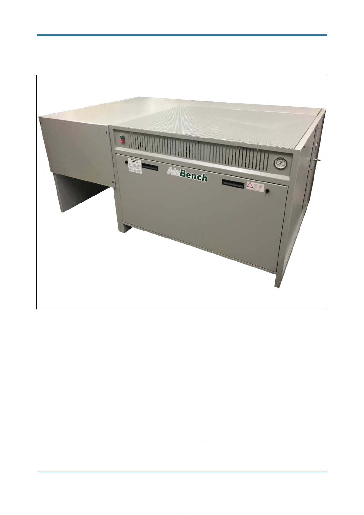
Unpack the unit and check for damage, if not already completed.
The AirBench must be installed on a flat and level floor capable of carrying the weight of the unit. For nominal
unit weights, see Specifications section at rear of manual. When determining an installation location, be aware
that the air exhaust must discharge somewhere. Do not position the unit so all outlets are blocked.
These models are designed to be moved into place using a forklift or pallet truck, taking care not to damage
fittings on the base of the unit.
Please note installation may be required when using certain accessories, external fansets, or ducting (see
below).
Electrical
WIRING
AirBench is supplied as standard with an internal fan or fans. These are pre-wired to a switch or speed
controller and fitted with a lead and plug for your convenience. Standard electrical supply is 240V/1Ph/50Hz.
Certain models can be supplied with 110V/1Ph/50Hz internal fans if specified in advance; this is noted on the
front left of each unit where applicable.
BS7671 requires that the lead is appropriate for the working environment and you must satisfy yourself that
the pre fitted lead is satisfactory.
EARTH BONDING
A stud is provided for use where appropriate e.g. in cases where equipotential bonding is required or where an
external fan is fitted.
If in doubt consult a qualified electrician.
FUSES
Switched units: A fuse is provided on the switch front plate.
Speed controlled units: An additional fuse is provided within the speed control panel. To check this fuse,
remove the service panel; the speed control panel is mounted on the rear of the service panel.
Compressed Air
AirBench RP requires a compressed air supply at 5 bar. Supplied air must be clean, and oil/moisture free.
Contaminated air will result in poor cleaning of filters, filter degradation, or failure of components. We
recommend installation of a shut-off valve, bleed-type regulator with gauge, filter, and condensate filter prior to
the air inlet to the AirBench.
© Copyright AirBench Ltd 2016
Page !of !6 19

An overpressure bleed valve is provided within the unit and is preset at 5.5bar. If the bleed valve is releasing,
turn down the supply pressure to the unit.
Assembly of Accessories
These items apply only when they have been ordered with the AirBench.
FRONT DEFLECTOR
If a deflector skirt is supplied loose with the unit, the unit must be raised slightly to allow the skirt to be fitted.
A pack of fixing bolts is supplied with the skirt; threaded inserts are fitted to the base of the bench to allow
attachment of the deflector. To fit, position the deflector skirt, and use the bolts to fix to the base of the bench.
Where a front deflector is supplied, ensure air is allowed to exhaust from sides or rear to avoid
motor overload.
ENCLOSURE
Enclosures are supplied fully assembled where possible. Where shipping does not permit assembly prior to
dispatch, enclosures should be assembled as follows using bolts supplied:
-!Loosely fit left and right panels to left and right frame of bench.
-!Loosely fit rear panel with assistance if required.
-!Lay top panel (if supplied) on top of enclosure and bolt into position.
-!Tighten all bolts.
© Copyright AirBench Ltd 2016
Page !of !7 19

COMMISSIONING
General
The initial commissioning and testing of your AirBench has been performed prior to delivery. However, as part
of in-house commissioning we recommend that you complete the following tasks and record the results as
appropriate in the system logbook.
In House Commissioning
The following tasks should be completed by a responsible person; for example, the Health and Safety Officer,
or Director, responsible for this process.
-Review the commissioning certificate for this unit, in particular any notes made by our engineer in relation to
use.
-Ensure all operators are trained to use this machine and are aware of the effective capture zone in which
they should aim to work.
-Ensure all operators are aware of the filter maintenance routine required for this machine.
Once complete, you should note this on the commissioning certificate and retain the certificate for future
reference.
As operating conditions vary, each installation will vary in maintenance needs and this is best established by
empirical means, regularly checking filter condition in the first weeks of operation to establish a procedure.
Reduced airflow is a key indication of filter condition. If the filter pressure gauge on the front of the unit is
showing in the red zone, this indicates low airflow and filters should be checked and cleaned or changed
promptly, according to the instructions contained within this manual.
We recommend keeping the commissioning certificate, Quick Start guide, and logbook with the machine at all
times for operator access.
If in doubt please contact the manufacturer quoting the machine serial number.
Fume Extraction Units
The effectiveness of carbon filtration improves as airspeed is lowered allowing fumes to spend longer passing
through the filters. A speed controller is supplied with carbon filtered units to allow airflow to be adjusted to the
optimum level.
We therefore recommend adjusting the speed controller provided to the lowest level at which extraction is still
effective and marking this operation point on the speed controller. Ongoing adjustment may be required as
filters become blocked with use.
© Copyright AirBench Ltd 2016
Page !of !8 19

OPERATION
This page contains the same information as the Quick Start guide provided with your AirBench.
Prior to use
Check the system logbook to ensure no routine maintenance is required.
General use
To use AirBench, ensure it is plugged in to a mains socket and the socket is switched on. Turn on the switch
on the front of the bench.
If a speed controller is fitted, turn it to full power before switching on, then adjust it to an appropriate level. Our
recommended settings are shown below:
During commissioning, an optimum setting may have been determined and this should be noted in the system
logbook.
Check the filter pressure gauge on the front of the bench. If the needle on the gauge is showing within the RED
zone, check the filter condition – they may require cleaning or replacement.
Your AirBench has a zone above the surface in which capture is most effective, extending between 50cm and
1m in a straight line upwards from the ventilated area. This zone forms a box in which you should aim to do
the majority of your work. Working outside this zone may reduce the effectiveness of the extraction.
Work as normal, aiming to work within the extraction zone described above. On completion of work, switch
the AirBench off using the switch on the front. Record any maintenance you have undertaken, or any that is
required, in the logbook.
Filter Cleaning
The filters in this unit are cleaned using a pulse of compressed air directed into the filters from the clean side.
This pulse will knock the dust from the filters into removable bins at the base of the unit.
To operate the pulse cleaning routine – first, stop work. Then, with fan running at full power, press and hold the
Green button on the front of the unit for approximately 2 seconds. The first pulse will fire and the air tank will
Fume: 50-75%
Light dusts, 50-100%
Heavy dusts, 75-100%
To avoid fan overload, do not block more than 95% of the work surface or the air
outlet.
"
© Copyright AirBench Ltd 2016
Page !of !9 19

begin to recharge. The second and third filters will be cleaned at approximately 10 second intervals. Wait until
all 3 pulses have completed before resuming work.
© Copyright AirBench Ltd 2016
Page !of !10 19

MAINTENANCE
Filter care
The filters must be maintained / cleaned / replaced as described below. Proper filter care is essential for the
effective operation of your AirBench. If in doubt, contact the manufacturer for advice.
When changing filters, the seals on which the filters sit should be checked for damage and replaced if
necessary.
All filters should be regularly checked for wear, damage, or by-passing.
When completing filter maintenance activities these should be recorded in the accompanying log sheet.
MAIN FILTER ACCESS
Main (Cartridge) Filters are accessed by turning the quarter turn latches on the front cover to loosen and
opening the front panel. Filters can be released by undoing the hand wheels and slid forward to remove.
Filters can also be accessed by lifting the top surface (taking care as these surfaces may have sharp edges).
HEPA FILTER ACCESS
The final stage HEPA filter (if fitted) is located in the filter unit to the left hand side of the machine. This can be
accessed by removing the front door panel; then releasing the clamps holding the filter into position.!
Take precautions and wear appropriate PPE when handing filters.
They may contain hazardous dusts.
"
Surfaces can be heavy and have sharp edges.
Wear appropriate hand protection.
"
© Copyright AirBench Ltd 2016
Page !of !11 19

Spares
See the specific list for your machine shown on the commissioning certificate.
When ordering, please contact the manufacturer quoting the serial number of this machine.
© Copyright AirBench Ltd 2016
Page !of !12 19

Other routine maintenance
We recommend the following tasks be performed on a regular basis. Suggested intervals are shown and these
should be reviewed dependent on level of use. Actual completion of these operations and any variation to
these recommended maintenance intervals should be recorded in the system logbook.
If completion of routine maintenance tasks suggests additional issues, contact the manufacturer for advice.
SURFACE
At least monthly, or as routine, check the surface condition. Clear any blocked holes.
FAN CHAMBER
At least every 6 months, check the fan chamber. Remove any debris and clean.
FAN
At least annually, check and tighten fan fixings, impeller fixings, and electrical connections.
© Copyright AirBench Ltd 2016
Page !of !13 19

ACCESSORIES
Some accessories are only supplied if specified with purchase.
Filter Pressure Gauges
A filter pressure gauge is fitted as standard to the front of each AirBench. This indicates performance of the
unit as a whole, and filter condition. Certain models show a red zone on the filter gauge; when the gauge
indicates within this zone, filters may be blocked or require cleaning. Turn the AirBench off and inspect the
filters.
Where no red zone is shown, a filter inspection pressure drop will be recorded on the Commissioning
Certificate. When pressure loss is greater than that shown on the Commissioning Certificate, follow the above
procedure.
A high pressure reading may also indicate a blocked surface. Inspect the surface for blockages and clean if
required. Do not operate AirBench continuously with more than 75% of the surface blocked.
Hours Run Meter
The meter is not resettable and operates at all times when the speed control or switch is powered.
Wheels
Standard industrial rubber wheeled swivel castors are used. The two front wheels are lockable. Lock by
pressing on the lever and trip by flicking (models and operation vary slightly). Do not attempt to move while
brakes are on.
Compressed Air Interlink
This option ensures the safety of operators by preventing the use of air tools without extraction being
operational; and reduces energy use by switching off the fan after 5 minutes of non-use.
4 off series 19 airline connectors are provided to the front or side of the unit and an internal timer fitted, pre-set
to an agreed value – usually 5 minutes. The control panel is supplied with an additional Red / Green push-
button.
System control will be as follows:
Switch main on/off switch to On – system is energized. Airline is switched to operational.
Press green button – fan starts and runs for 5 minutes.
Use airline or press green button again – timer is reset for a further 5 minutes.
Press red button – fan stops, airline stops.
The timer can be re-set to a different interval; contact the manufacturer for details.!
© Copyright AirBench Ltd 2016
Page !of !14 19

THOROUGH EXAMINATION AND TESTING
If AirBench is used as an LEV system it must be tested at regular (normally 12 month) intervals and certificated
under the COSHH regulations. This service is available from us, or our approved testers.
Thorough examination and test should include:
-Ensuring the prescribed maintenance routines are being completed and recorded within the system
logbook.
-Condition check of fan, filters, electrics.
-Performance testing according to recommended face velocities.
-Visual check that operators are working within effective area.
-Visual check of effectiveness using, for example, smoke tubes.
Recommended face velocities are as follows:
Fume control: Minimum 0.5m/s
Light dust control: Minimum 1.0 m/s
Heavy dust control: 1.2 – 1.5m/s
Completion of Thorough Examination and Testing should be recorded within the system logbook.!
© Copyright AirBench Ltd 2016
Page !of !15 19

TECHNICAL
Arrangement - RP1212
"
© Copyright AirBench Ltd 2016
Page !of !16 19

Arrangement - RPL1212
"
© Copyright AirBench Ltd 2016
Page !of !17 19

Arrangement - RP1920
"
Technical Data
Data shown is for standard models. Check the Commissioning Certificate for details specific to your unit.
Model
Width
Depth
Height
Weight
Fan Power
Max Current
(mm)
(mm)
(mm)
(kg)
(kw)
(a)
RP1212
1274
1300
900
140
0.74
3.9
RPL1212
1950
1300
900
180
0.74
3.9
RP1920
1950
960
900
160
0.74
3.9
© Copyright AirBench Ltd 2016
Page !of !18 19

DECLARATION OF CONFORMITY
BY
AIRBENCH LIMITED
RELEVANT DIRECTIVES
EMC Directive 2004/108/EC (when connected to standard mains sinusoidal supply).
Machinery Directive 2006/42/EC
Low voltage Directive 2006/95/EC
- EN-60204–1:2006 (Safety of machinery, electrical equipment of machines, general requirements).
- EN-60335-2-80 (Safety requirements for electric fans and regulators).
We; AIRBENCH Limited, declare that “AirBenches” when supplied as self contained equipment comply with
the directives detailed above and therefore comply with requirements of the Low Voltage Directive.
"
Simon Cook
Manufactured by:
AirBench Ltd.
14 Grange Farm Road,
Colchester,
Essex.
CO2 8JW
Responsible Person:
Simon Cook
Description:
Ventilated work bench known as “AirBench”
© Copyright AirBench Ltd 2016
Page !of !19 19
This manual suits for next models
3
Table of contents
Other AirBench Industrial Equipment manuals
Popular Industrial Equipment manuals by other brands

Sapphire Audio
Sapphire Audio 2500HS Operation manual

Venmar
Venmar AVS HRV EKO 1.5 quick start guide

Bard
Bard 11EER WA Series User's Application Guide

PCB Piezotronics
PCB Piezotronics 1322-01A Installation and operating manual

Condux
Condux 08097100 User's guide & safety manual

Dodge
Dodge Imperial instruction manual