ABB ProKiln GAC400 User manual

—
ABB MEASUREMENT & ANALYTICS |
OPERATING INSTRUCTION | OI/GAC400-EN REV. A
ProKiln GAC400
Probe gas sampling system
—
ABB Measurement & Analytics
For your local ABB contact, visit:
www.abb.com/contacts
For more product information, visit:
www.abb.com/analytical
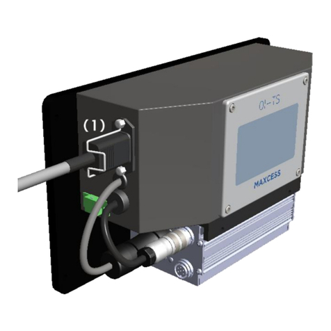
Sampling system for dry gas
sampling at rotary cement kiln gas
exit and calciner gas exit.
Measurement made easy
OI/GAC400
-EN Rev. A 09.2023 Original Instruction
—
ProKiln GAC400
Introduction
The ProKiln
sampling system is especially
designed for analysis in hot cement flue gases
with high content of dust and aggressive gas
components. The system is made by cement
specialists for use in the rough environment of a
cement plant.
The ProKiln sampling system is preferably
combined with ABB’s AO2000 System. However,
the ProKiln sampling system is built to be self
-
supporting which allows it to easily be connected
and retrofitted to any existing well
-functioning
gas analysis system or
other third-part suppliers
solution.
The system controller interface offers a large
variety of industry leading communication
options together with conventional terminal
based digital and analogue status signals.
Additional Information
Additional documentation on
ProKiln GAC400 is
available for download free of charge at
www.abb.com/
analytical.
Alternatively simply scan this code:
—
We reserve the right to make technical changes or
modify the contents of this
document without prior
notice. W ith regard to purchase orders, the agreed particulars
shall prevail.
ABB does not accept any
responsibility whatsoever for potential errors or possible lack
of information in this document.
We reserve all rights in this document and in the
subject matter and illustrations
contained therein.
Any reproduction, disclosure to third parties or utilization of its
contents
– in whole or in parts – is forbidden without prior written consent of ABB.
© ABB 2023 3KXG174400R4201

2 ProKiln GAC400 PROBE GAS SAMPLING SYSTEM | OI/GAC400-EN REV. A
Table of contents
1General........................................................................ 3
About these operating instructions ...................................... 3
Notifying service........................................................................ 3
2Safety..........................................................................4
General information and instructions...................................4
Warnings...................................................................................... 4
Intended use ............................................................................... 5
Improper use............................................................................... 5
Basic safety rules ....................................................................... 5
Overview of dangers ................................................................. 7
Protective installations .......................................................... 10
Requirements to be met by personnel................................ 12
Personal safety equipment.................................................... 12
Warranty provisions ................................................................ 13
Cyber security disclaimer....................................................... 13
Software downloads............................................................... 13
Manufacturer’s address ......................................................... 13
Service address ........................................................................ 13
3Design and function ................................................ 14
Overview .................................................................................... 14
Mode of functioning and operation .................................... 15
Components ............................................................................. 18
Control system .........................................................................26
User interfaces .........................................................................28
Access permissions.................................................................28
Default operation parameter settings ...............................30
4Product identification ............................................34
Name plates ..............................................................................34
Warning signs on the system................................................34
5Transport and storage............................................36
Safety instructions ..................................................................36
Transport...................................................................................36
Unpacking the system ............................................................38
Scope of delivery......................................................................38
Storing the system ..................................................................39
6Installation .............................................................. 40
Safety instructions ................................................................. 40
Introduction ............................................................................. 40
Overview of instruction steps.............................................. 40
Checking site conditions........................................................ 41
Installing the probe retractor/flange shutter...................42
Installing the probe .................................................................44
Installing the compressed-air supply..................................48
Installing the control cabinet ................................................48
Installing the water system and cooling panel .................48
Installing the heated sample gas line to the retractor....50
7Electrical connections............................................. 51
Safety instructions .................................................................. 51
Connecting internal electric cables ..................................... 51
Connecting external electric cables ....................................54
8Commissioning ....................................................... 56
Safety instructions.................................................................. 56
Overview of instruction steps ...............................................57
Installation check .....................................................................57
Cooling water........................................................................... 58
Air supply................................................................................... 58
Activation of the probe gas sampling system.................. 59
Working on the cooling module........................................... 62
Checking the pneumatic system ......................................... 62
Starting frequency converter and adapting control
parameters ............................................................................... 63
Checking/correcting operating parameters .................... 64
Inserting the probe and switching to automatic mode . 64
9Operation................................................................. 66
Safety instructions.................................................................. 66
Monitoring automatic mode ................................................ 67
Checking general condition .................................................. 69
Adapting the cleaning procedure of the probe................ 69
Using the EMERGENCY-STOP switch .................................. 71
Human Machine Interface (HMI)........................................... 71
10 Diagnosis / error messages ...................................73
Automatic processes...............................................................73
Irregularities and corrective action......................................73
HMI error displays................................................................... 74
Handling error messages ...................................................... 78
11 Maintenance ............................................................ 80
Introduction.............................................................................. 80
Maintenance schedule.............................................................81
Equipment layout plan ........................................................... 83
Acquiring spare parts and wear parts................................ 98
Safety instructions for maintenance work........................ 98
Maintenance work................................................................. 100
12 Decommissioning ..................................................124
Safety instructions.................................................................124
Shutting down the system...................................................124
13 Dismounting and disposal....................................126
Safety instructions.................................................................126
Disassembling the system...................................................127
Disposing of the system.......................................................127
14 Specification ..........................................................128
Dimensions and weights ......................................................128
Sound emissions ....................................................................128
15 Additional documents...........................................129
16 Appendix .................................................................130
Return form ............................................................................ 130
ProKiln GAC400 PROBE GAS SAMPLING SYSTEM | OI/GAC400-EN REV. A 3
1General
About these operating instructions
Scope and purpose
These operating instructions apply to the ABB ProKiln GAC400
Probe gas sampling system for gas sampling at rotary cement
kiln inlet, riser duct and calciner gas exit.
These operating instructions are intended to give all personnel
handling the probe gas sampling system the information
required to perform the following tasks correctly and safely:
• Transport at the company (for first-time delivery,
relocation, storage, putting back into operation)
• Set-up, unpacking and connection
• Start-up
• Operation
• Diagnostics and troubleshooting
• Maintenance
• Shutting down, disassembly, putting back into operation,
storage, and disposal
Target group
These operating instructions are intended for the following
groups:
• Process engineers and design engineers (for preparation
of the installation site)
• Transporter
• Assembly personnel
• Start-up personnel
• Operating personnel
• Maintenance personnel
• Storage personnel
• Disposal personnel
Illustrations in the operating instructions
The illustrations in the operating instructions do not always
depict the actual layout of a probe gas sampling system as
delivered. Therefore, the drawings in the supplied system
documentation are always authoritative.
Failure to observe the operating instructions
Failing to observe the information in this document can lead to a
risk of damage to property, injuries or even death. In order to
ensure safety, all personnel handling the probe gas sampling
system must have read and understood the following sections of
this document before commencing any work:
• The section Safety on page 4.
• The sections describing the work to be performed.
Liability
The manufacturer is not liable for damage and disruptions
resulting from a failure to observe these operating instructions
and other applicable documents. The manufacturer of this
equipment can never be liable for any process disruptions or
hazardous or dangerous process conditions as the process
responsibility of operation is entirely placed at the process
operator’s overall evaluation.
Notifying service
Who should you contact for further help?
Please contact your local service representative.
For emergencies, please contact ABB Service:
Telephone: +49-(0)180-5-222 580
Fax: +49-(0)621-381 931 29031
E-mail: de-support-analytical@abb.com
Before you notify service…
Before you notify service because of a malfunction or a status
message, please check whether there actually is an error and
whether the system is actually operating out of specifications.
When you notify service…
When you notify service because of a malfunction or a status
message, have the following information available:
• The serial number of the system, you can find it on the type
plate,
• An exact description of the problem or status as well as the
status message text or number.
This information will enable the service personnel to help you
quickly.

4 ProKiln GAC400 PROBE GAS SAMPLING SYSTEM | OI/GAC400-EN REV. A
2Safety
General information and instructions
These instructions are an important part of the product and
must be retained for future reference.
Installation, commissioning, and maintenance of the product
may only be performed by trained specialist personnel who have
been authorized by the plant operator accordingly. The specialist
personnel must have read and understood the manual and must
comply with its instructions.
For additional information or if specific problems occur that are
not discussed in these instructions, contact the manufacturer.
The content of these instructions is neither part of nor an
amendment to any previous or existing agreement, promise or
legal relationship.
Modifications and repairs to the product may only be performed
if expressly permitted by these instructions.
Information and symbols on the product must be observed.
These may not be removed and must be fully legible at all times.
The operating company must strictly observe the applicable
national regulations relating to the installation, function testing,
repair and maintenance of electrical products.
Warnings
The warnings in these instructions are structured as follows:
DANGER
The signal word ‘DANGER’ indicates an imminent danger.
Failure to observe this information will result in death or
severe injury.
WARNING
The signal word ‘WARNING’ indicates an imminent danger.
Failure to observe this information may result in death or
severe injury.
CAUTION
The signal word ‘CAUTION’ indicates an imminent danger.
Failure to observe this information may result in minor or
moderate injury.
NOTICE
The signal word
‘NOTICE’
indicates possible material damage.
Note
‘Note’ indicates useful or important information about the
product.

ProKiln GAC400 PROBE GAS SAMPLING SYSTEM | OI/GAC400-EN REV. A 5
Intended use
The probe gas sampling system is used to continuously monitor
process gas in cement production:
• at primary firing at the kiln inlet of the rotary kiln
• at secondary firing at the process gas outlet of the
calciner
Analysis of the sample gas is performed by means of a suitable
continuous gas analyser system, for example the AO2000-
System, AO2000 Series or EL3000 Series from ABB AG, or any
existing well-functioning gas analysis system or other third-
party supplier's solution.
The continuous gas analyser system technology can be based on
cold/dry or hot/wet.
Improper use
The probe gas sampling system may not be used:
• to sample mixtures of gas/air or gas/oxygen that are
capable of ignition during normal service.
• to sample flammable gas which may form an explosive
mixture in combination with air or oxygen.
• in a potentially explosive atmosphere or in explosion-
hazard areas.
• to sample extremely toxic or extremely corrosive gases.
• in process temperatures above 1400 °C (2552 °F).
• in process dust loads higher than 2000 g/m³ (2 oz/in³).
• in condensing process conditions.
Further actions that may cause damage to the ProKiln system or
lead to hazardous situations:
• Forcing the ProKiln probe into the kiln while the flange
into the kiln is completely blocked.
• Forcing the use of the air blasters when the probe is not
in a safe position inside the kiln.
The restrictions of the gas analysis system have to be checked
separately.
Basic safety rules
Target group for these rules
These rules are intended for all persons handling the probe gas
sampling system in any situation.
Purpose of these rules
The purpose of these rules is to ensure that all persons handling
the probe gas sampling system are thoroughly informed about
risks and safety measures and that they observe the safety
instructions in the operating instructions and on the system.
Failing to observe these rules can lead to a risk of damage to
property, injuries or even death.
Handling the operating instructions
Observe the following rules:
• Completely read through the Safety section and the sections
pertaining to your work. You must have understood these
sections.
• Always keep the operating instructions handy nearby the
probe gas sampling system for reference.
• Pass on the operating instructions if the probe gas sampling
system is re-sold.
Handling the probe gas sampling system
Observe the following rules:
• Only persons fulfilling the requirements specified in these
operating instructions may handle the probe gas sampling
system.
• The probe gas sampling system may only be used for the
intended purpose. Never use the probe gas sampling system
for any other purposes, even if they appear reasonable.
• Take all safety measures specified in these operating
instructions and on the system. Specifically, use the
prescribed personal safety equipment.
• Only work in the designated work areas.
• Do not make any modifications to the probe gas sampling
system, e.g. by removing parts or attaching non-approved
parts. Specifically, do not change or disable any protective
installations.
• Use only original spare parts when replacing defective
components.
• The probe gas sampling system may only be operated if
maintenance work is performed regularly and expertly.

6 ProKiln GAC400 PROBE GAS SAMPLING SYSTEM | OI/GAC400-EN REV. A
… 2 Safety
… Basic safety rules
Operator's obligations towards personnel
The operator must ensure:
• that personnel meet the requirements for their tasks.
• that personnel are provided with the personal safety
equipment specified in these operating instructions and, if
necessary, additional safety equipment against risks posed
by the installation site, e.g. by noise.
• that personnel are provided with maintenance equipment in
order to secure the service switch, e.g. padlocks.
• that the system has protection against restarting the power
supply in order to ensure that the system is powered off
when the main switch is switched off to prevent
unauthorized activation of the power supply.
• that personnel have read and understood these operating
instructions before they handle the probe gas sampling
system.
• that personnel are regularly and recurrently instructed about
the risks and safety measures when handling the probe gas
sampling system.
• that the work areas of the probe gas sampling system are
adequately aired and illuminated.
• that the safety regulations in force in your country are
observed.
• that the safety regulations pertaining to setting up and
operating electrical equipment in force in your country are
observed.
• that the safety regulations pertaining to handing gases,
lubricants, etc. in force in your country are observed.
Procedure in the event of accidents
The probe gas sampling system is designed and built in such a
way that personnel can work with it without any risk. Despite all
precautions, however, unforeseeable accidents may nevertheless
occur in unfavourable circumstances. If cooling water tubes or
compressed-air tubes burst, shut down the probe gas sampling
system and secure it against being switched on again.
If errors are detected, shut down the system and secure it
against being switched on again. Before approaching the probe
gas sampling system, wait until the entire cooling water or the
entire compressed-air has been evacuated. If the switched-on
probe gas sampling system poses a danger, proceed as follows:
Aim
Action
Stop movement of the system
Press the EMERGENCY
-STOP switch
Note:
The probe interrupts its
movement immediately and in any
position. The probe is only retracted
out of the rotary kiln after turning the
service switch to service mode,
releasing the EMERGENCY
-STOP
switch, and operating the probe
retractor in manual.
Disc
onnect the system from the main
and UPS power supplies
Turn off the main and UPS power
switch on the side of the control
cabinet.
Turn off the safety breaker on the door
of the Retractor rear panel to prevent
all movement of the probe.
Evacuate the compre
ssed-air system
Close the MAIN VALVE on the retractor
unit or at the source outlet from the air
tank (if available)
If risk-free operation is no longer possible
If it can be assumed that safe operation is no longer possible,
the probe gas sampling system must be taken out of operation
and secured against being started up again. It can be assumed
that safe operation is no longer possible:
• If the probe gas sampling system is visibly seriously
damaged
• If the probe gas sampling system no longer works
• After prolonged storage under adverse conditions
• After severe transport stress
Further information
See the following sections:
• Intended use on page 5
• Overview of dangers on page 7
• Requirements to be met by personnel on page 12
• Personal safety equipment on page 12
• Protective installations on page 10

ProKiln GAC400 PROBE GAS SAMPLING SYSTEM | OI/GAC400-EN REV. A 7
Overview of dangers
Introduction
The probe gas sampling system is designed such that the
operator is protected against all dangers that can be reasonably
avoided by means of design. Due to the purpose of the probe
gas sampling system, however, there are nevertheless residual
risks that require precautions. The following section gives
information about the nature of these residual risks and their
effects.
Moving gas sampling probe
The probe moves in and out automatically. Expect a system-
actuated movement of the gas sampling probe at any time. The
gas sampling probe not only performs individual extension and
retraction movements, but also performs combined processes
involving successive extension and retraction movements.
This means:
• Risk of injury due to automatic extension and retraction
movements of the gas sampling probe if anyone is standing
in the retractor's area of travel.
• Danger of toxic, harmful gases when the shutter is open.
The above risks are valid if working inside the danger area
around the probe, all movement of the probe is stopped if the
safety device that permits access to the danger area is activated.
The safety device could be e.g., a locked gate, fence or barrier
that leads to the probe gas sampling system area.
Associated warning sign in this operating instruction:
WARNING
Gas sampling probe movements
Risk of crushing around the retractor due to gas sampling
probe movements.
• Before commencement any work on the probe gas
sampling system, turn the Safety switch to "Off” and
secure the service switch against unauthorized switching
(with a padlock).
• Additionally press the EMERGENCY-STOP switch before
working on the retractor or probe.
• Do not enter the danger area around the retractor until it
is at standstill and the warning lamps and buzzer are off.
• Never stand in the danger area around the retractor when
the protective installation is closed.
• When the warning lamps light up or the warning buzzer
buzzes, leave the danger area around the probe retractor
immediately as the probe is about to move at any
moment.
• Press the EMERGENCY-STOP switch immediately if anyone
is still in the danger area around the retractor after the
warning lamps light up or the warning buzzer buzzes.
Electrical components
The probe gas sampling system contains electrical and live
components.
This means:
Danger of electrocution,
• if covers on control cabinet, terminal box or power
connection are open. Connectors in the control cabinet or
terminal box may also live parts.
• if the connection between the protective earth connector
and a protective earth conductor is not made before all other
connections.
• if the protective earth conductor is interrupted inside or
outside the probe gas sampling system or the protective
earth connector is disconnected.
• if the set operating voltage and mains voltage do not match
before switching on.
• if work is performed on the open probe gas sampling system
without disconnecting probe gas sampling system from the
power supply.
• due to charged capacitors in the probe gas sampling system
even if probe gas sampling system has been disconnected
from all sources of power.
• due to fuses that do not match the specified type and
nominal current and/or repaired fuses.
Associated warning sign in this operating instruction:
DANGER
Danger to life due to live parts!
• Only specialized electrical personnel may work on the
electrical system.
• Disconnect the probe gas sampling system from the
power supply before working on the electrical
components.
• Observe national regulations pertaining to electrical
equipment.

8 ProKiln GAC400 PROBE GAS SAMPLING SYSTEM | OI/GAC400-EN REV. A
… 2 Safety
… Overview of dangers
Hot surfaces
During operation of the probe gas sampling system surfaces and
parts get hot.
This means:
• Danger of burning due to hot surfaces during and after
operation of the system.
Associated warning sign in this operating instruction:
WARNING
Hot surfaces
Danger of burning due to hot surfaces during and after
operation of the probe gas sampling system.
• Do not touch the probe gas sampling system during and
after operation.
• Do not touch the probe gas sampling system until it has
cooled down to 50 °C. Specifically, do not touch:
– the cooling module, the heated sample gas line
– the connection box for the heated sample gas line on
the retractor
– the hot sampling filter
– the entire probe
– the metal structure of the retractor
– the shutter of the duct opening
• If it is unavoidable to touch hot components, wear a face
mask against heat, heat-proof gloves and protective
welder's clothing.
Harmful gases at the duct opening
When the shutter is open, gases flow out of the rotary kiln duct
opening that may be harmful to health.
This means:
• Danger of poisoning due to harmful gases.
• Danger of burning due to jets of flame at the duct opening.
Associated warning sign in this operating instruction:
WARNING
Hot surfaces, hot gases, jet flames
Risk of burning due to jet flames and hot gases at the
uncovered duct opening when the rotary kiln is in operation.
• Preferably install or remove the probe when the rotary kiln
is out of operation.
• If you install or remove the probe when the rotary kiln is in
operation:
– Wear a face mask against heat, heat-proof gloves and
protective welder's clothing and respiratory protection
against toxic gases.
– Keep the time in which the duct opening is open as
short as possible.
Hot cooling water
During operation of the probe gas sampling system, the cooling
water in the cooling system gets very hot.
This means:
• Danger of scalding in the event of contact with the hot
cooling water.
• Danger of burning in the event of contact with the cooling
water tubes.
Associated warning sign in this operating instruction:
CAUTION
Hot cooling water
Danger of injury to skin and eyes in the event of contact with
hot cooling water
• Avoid contact with the cooling water as it is hot.
• In case of accidental contact with hot cooling water wash
off immediately with cold water.
• Contact medical specialist according to local regulations.
• If hot cooling water gets in the eyes despite protective
glasses, rinse them thoroughly under cold running water,
holding the eyelids open. Contact medical specialist
according to local regulations.
Anti-freeze in the cooling water
The cooling system can contain cooling water with anti-freeze in
regions experiencing below freezing point temperatures.
This means:
• Danger of injury to skin and eyes in the event of contact with
anti-freeze.
Associated warning sign in this operating instruction:
CAUTION
Harmful anti-freeze
Danger of injury to skin and eyes in the event of contact with
cooling water or anti-freeze.
• Avoid contact with the cooling water and the anti-freeze.
• In case of accidental contact of cooling water or anti-
freeze with skin, wash off the skin immediately with water
and soap. Contact medical specialist according to local
regulations.
• If cooling water or anti-freeze gets in the eyes despite
protective glasses, rinse them thoroughly under running
water, holding the eyelids open. Contact medical specialist
according to local regulations.
• Observe instructions in the anti-freeze manufacturer's
safety data sheet.

ProKiln GAC400 PROBE GAS SAMPLING SYSTEM | OI/GAC400-EN REV. A 9
Compressed-air in the pneumatic system
The pneumatic system contains compressed-air.
This means:
• Danger of eye injuries if compressed-air escapes, e.g., if
compressed-air tubes burst, when opening screw
connections or inadvertently opening compressed-air tubes
with no additional connector.
Associated warning sign in this operating instruction:
WARNING
Pressurized system dangers
Risk of injury in the area of the probe gas sampling system
due to pressurized pneumatic system.
• All pneumatic equipment connected must be fulfilling local
standards for safety and usage.
• Periodic inspection/approval of installation according to
local standard.
• Any damage to a pneumatic equipment will require a
replacement in order not to compromise safety integrity

10 ProKiln GAC400 PROBE GAS SAMPLING SYSTEM | OI/GAC400-EN REV. A
… 2 Safety
Protective installations
Introduction
The probe gas sampling system is fitted with protective installations to protect the operator. All protective installations must be in
place and operational during operation. The protective installations must not be disabled and must be checked for proper
functioning at regular intervals.
The illustration below shows the location of the protective installations on the probe gas sampling system.
1
EMERGENCY-STOP switch
2
Covers
3
Warning lamps and buzzer (warning tower)
4
Flange shutter (optional)
5
Protective fence installation with electric lock access
Figure 1: Probe gas sampling system – location of the protective installations
1
1
1
2
2
2
4
2
3
3
5

ProKiln GAC400 PROBE GAS SAMPLING SYSTEM | OI/GAC400-EN REV. A 11
EMERGENCY-STOP switch
Location
• Rear end of the retractor
• Right side of control cabinet
Function
Interrupts movement of the gas sampling probe and blow-
back of the probe. The gas sampling probe can only move
again when the EMERGENCY-STOP switch is unlocked and
reset by pressing the service switch.
Covers
Location
• Retractor
• Cooling module
Function
Protection from inserting hand into the system.
Warning lamps and buzzer (warning tower)
Location
• Retractor terminal
• Control cabinet
Function
Warning about probe movement. The warning lamps flash in
the following situations:
• Automatic mode: approximately 10 seconds before
probe movement
• Manual mode: immediately after pressing the "Retract
probe" button
• Error: immediately before probe retraction
Flange shutter (optional)
Location
On the duct opening of the rotary kiln
Function
• Protects from jet flames, hot material, and gases from
the duct opening.
• Closes the kiln's duct opening when the probe is
retracted.
• A manual lock ensures that the duct opening is reliably
closed when working near the duct opening.
Protective fence installation with electric lock access
Location
Protective fence installation with electric-lock access (the
protective fence or gate installation is the responsibility of
the operator)
Function
• Prevents anyone from standing near the retractor when
probe movement is possible. No probe movement is
possible when the protective installation is open.
• When the protective installation is opened during
operation, the warning lamps flash, the warning buzzer
buzzes and any probe movements or probe cleaning stop
until protective installation is closed and cleared by
entering service mode.
Additional EMERGENCY-STOP switch
A customer supplied EMERGENCY-STOP switch can be installed
additionally by the operator. This input to the control system will
have the same function as the enclosed EMERGENCY-STOP
switch described above.
The additional EMERGENCY-STOP switch must be installed if the
above-described EMERGENCY-STOP switch is difficult to access.
The EMERGENCY-STOP switch will be connected into the
emergency safety circuit of the control system and work with
the same effect as the two integrated EMERGENCY-STOP
switches.

12 ProKiln GAC400PROBE GAS SAMPLING SYSTEM | OI/GAC400-EN REV. A
… 2 Safety
Requirements to be met by personnel
Personnel qualifications
Personnel handling the probe gas sampling system must meet
the following requirements:
Personnel
Task
Required qualification
Transporter
•
Transport in the company
•
Unpacking of the system
Trained crane
operator/fork
-lift driver
with e
xperience with
lifting apparatus
Mechanical fitter
•
Mechanical installation
•
Mechanical disassembly
Mechanical expert
Electrical fitter
•
Electrical installation
• Electrical disassembly
Electrical expert
Start
-up personnel
•
Initial start-up
•
Putting back into
operation
Technician familiar with
the processes of cement
production and specific
work co
nditions
Operator
Operation
Trained worker
Mechanical
maintenance personnel
•
On mechanical parts:
•
Maintenance
•
Troubleshooting
•
Maintenance
•
Shutting down
Mechanical expert
Electrical maintenance
personnel
•
On mechanical parts:
•
Maintenance
•
Troubleshooting
•
Maintenance
• Shutting down
Electrical expert
With
e
xperience with
controllers
Storage personnel
•
Correct storage
•
Packing of the system for
transport
Trained unskilled worker
Disposal personnel
•
Disposal of the probe gas
sampling system
Trained disposal
personnel
Personal safety equipment
General protective equipment
The following general protective equipment must be worn when
performing any work in the area of the probe gas sampling
system:
• Closed overalls with long trousers and long sleeves
• Safety shoes (preferably boots covering ankles)
• Safety gloves suitable for mechanical work
• Safety glasses
• Protective helmet
• If necessary, additional protective equipment if prescribed
by the operator
Additional protective equipment
The following additional protective equipment is required when
performing maintenance work:
Dust mask
Face mask against heat
Heat-proof gloves and protective welder's clothing
Respiratory protection against toxic gases from the rotary kiln

ProKiln GAC400 PROBE GAS SAMPLING SYSTEM | OI/GAC400-EN REV. A 13
Warranty provisions
Using the device in a manner that does not fall within the scope
of its intended use, disregarding this manual, using
underqualified personnel, or making unauthorized alterations
releases the manufacturer from liability for any resulting
damage. This renders the manufacturer's warranty null and void.
Cyber security disclaimer
This product is designed to be connected to and to
communicate information and data via a network interface. It is
operator’s sole responsibility to provide and continuously ensure
a secure connection between the product and your network or
any other network (as the case may be).
Operator shall establish and maintain any appropriate measures
(such as but not limited to the installation of firewalls,
application of authentication measures, encryption of data,
installation of anti-virus programs, etc.) to protect the product,
the network, its system and the interface against any kind of
security breaches, unauthorized access, interference, intrusion,
leakage and/or theft of data or information.
ABB and its affiliates are not liable for damages and/or losses
related to such security breaches, any unauthorized access,
interference, intrusion, leakage and/or theft of data or
information.
Software downloads
By visiting the web page indicated below, you will find
notifications about newly found software vulnerabilities and
options to download the latest software. It is recommended that
you visit this web page regularly:
www.abb.com/cybersecurity
Manufacturer’s address
ABB AG
Measurement & Analytics
Stierstädter Str. 5
60488 Frankfurt am Main
Germany
Tel: +49 69 7930-4666
Email: [email protected]
Service address
If the information in this Operating Instruction does not cover a
particular situation, ABB Service will be pleased to supply
additional information as required.
Please contact your local service representative.
Customer service center
Tel: 0180 5 222 580
Email: automation.service@de.abb.com

14 ProKiln GAC400PROBE GAS SAMPLING SYSTEM | OI/GAC400-EN REV. A
3Design and function
Overview
The sampling system serves the purpose of continuous sampling of process gas at the measuring point, i.e. at the kiln inlet of the
rotary kiln or at the gas outlet of the calciner.
The probe forms a unit with the probe retractor. This integrates a recirculating water-cooling circuit with a non-pressurized water
buffer tank and a heat exchanger (cooling module).
The retractor and probe can be controlled from the HMI on the control cabinet. The sample gas is filtered in the probe tip and
conducted into the sample gas line. Any further conditioning of the analysis gas takes place in external equipment (not part of the
probe sampling system).
The following figure shows a general overview of the ProKiln GAC400 probe gas sampling system:
Figure 2: ProKiln GAC400 probe gas sampling system
The individual modules of the probe gas sampling system have the following functions:
Pos.
Designation
Function
1
Retractor
•
Mechanical movement of the probe
• Automatic removal of the probe when malfunctions occur
2
Probe
Sampling of sample gas from the process
3
Control cabinet
•
Operation of equipment
•
Control and monitoring
• Error display and communication
4
Water panel
Circulate cooling media (water) through the probe
5
Cooling unit
Remove process heat from cooling media
6
Flange shutter (Option)
Entry flange shutter device
7
270 l Air tank CE (Option)
Air tank
16
7
5
4
3
2

ProKiln GAC400 PROBE GAS SAMPLING SYSTEM | OI/GAC400-EN REV. A 15
Mode of functioning and operation
Modes of functioning
The following process takes place in order to sample gas during
cement production:
1. General power and UPS power is turned on.
2. Water panel and water cooling of the probe turned on.
3. Electrical heating for probe and sample hose is turned on.
4. Compressed-air (oil and water free) is turned on.
5. All unit and maintenance alarms need to be cleared before
system can enter operation.
6. The system must initially be started in manual mode.
7. The probe is inserted into the rotary kiln.
8. The system is then able to get switched into automatic
mode.
9. The probe gas sampling system will run the sequence of gas
sampling and probe cleaning based on set intervals.
10. The probe gas sampling system will run the sequence of
moving the probe in and out of the process based on set
intervals.
11. The system is switched to manual mode in case of specific
malfunctions or by operator decision.
12. The probe is retracted from the rotary kiln and the flange
shutter is closed.
Modes of operation
The following operating modes are possible:
Mode
Description
Automatic mode
Allows continuous operation of the system for gas
sampling. Probe cleaning steps and movement of the
probe in
and out of the process take place after set
intervals (these can be defined using the controller).
Manual mode
Allows operation of the system in manual mode, required
for maintenance, for example. Probe cleaning steps and
movements are controlled only manually by the operator.

16 ProKiln GAC400 PROBE GAS SAMPLING SYSTEM | OI/GAC400-EN REV. A
… 3 Design and function
… Mode of functioning and operation
Monitoring devices
Figure 3: System schematic
Refer to table on next page for further explanations.
M10
M20
M21
TT10
L
L1
L2
L3
F
F12
T
T11
Customer suppl 1 pipingy "
w2
w1
T
T12
Probe
V19
V10
w5
Dr in " Fa 1 /
V13
V11
V15
V14
T
T1
H1
Ce ter ipe
np
Filter periphery
V5
V3
H2
M
M1
V7
P
P1
H10
op i alt on
Prob langee f
V18
T
T2
V9
V12
V16
V1
V2
C1
w3
H3
T
T3
Filter blo bacw k
Co pres edm s
Air t n mina k
2 0 litre5
(Op io al)t n
Coo i g unitl n
W te panela r
R oetract r
Fl n e sh ttera g u
O ti nalp o
V4
E .lec Brake
Enco erd
Po rs eader
w4
Customer su pl 1 pipingp y "
a1
w6
w7
w8
Customer suppl 1 pipingy "
w9
a7
a8
a4 a3 a2
Dr in "/Fa 1
a6 a5
V5 1 - ptional. o
V5 2 tional. - op
Pos 1
Pos 0
V5 3 tional. - op
P turge Ven .
V6
Includedcomp. air connect o p ints:i n o
a1 1" alv. pipe connect on/F g i
a2 1" hose stu connectionb
a3 1" hose stu connectionb
a4 ½” h stub connectionose
a5 6mm ageloksw
a6 6mm ageloksw
Customer u ies:s ppl
A7 Compress d air pplye su
(8 a oil & water free)b r
a1-a8 1" galv pi connect on. pe i
Included water connecti s ints:on po
w1 1"/F galv. unio connectionn
w2 1"/F galv. union on ectionc n
w3 1"/F galv. unio connectionn
w4 1"/F galv. unio connectionn
w5 1"/F galv. unio connectionn
w6 1"/F galv. unio connectionn
w7 1"/F galv. unio connectionn
w8 1"/F galv. unio connectionn
w9 1"/F galv. unio connectionn
Customer u ies:s ppl
w5 Wat r otable qual.)e (p
w1-w3 1" lv pipe connectionga
w2-w4 1" lv pipe connectionga
w6-w7 1" lv pipe connectionga
w8-w9 1" lv pipe connectionga
V8
Sample
cnne t no c io
point
Cu omerst
w erat
s pu ply 1"
C tomerus
com essed airpr
supply 1"
8 bar and wateroil
free

ProKiln GAC400 PROBE GAS SAMPLING SYSTEM | OI/GAC400-EN REV. A 17
The process is monitored by the following devices (see Figure 3 for a detailed drawing):
Monitoring
position
Monitoring device
Purpose
Function
F12
Cooling water flow measurements
•
Protects the probe against overheating
•
Monitors the cooling water pump for adequate
pump power
•
Triggers the retraction program if minimum
cooling water flow is not reached
•
Cooling water pump function check
P1
Pressure switch
Ensures adequate compressed-air reserve
Locks various follow up functions
T1
Probe sample tube temperature
Protects probe against condensation build
-up
inside
Locks various follow up functions
T2
Probe sample hose temperature
Protects probe against condensation build
-up
inside
Locks various follow up functions
T3
Heated sample connection point
temperature
Protects probe against condensation build
-up
inside
Locks various follow up functions
T10
Cooling panel water tank tempera
ture
•
Monitors the cooling water temperature in the
holding tank
•
Monitors the efficiency of the water-cooling
unit
•
Turns the water-cooling unit fan on/off
•
Causes a water-cooling alarm to retract the
probe
•
Turns the water-cooling unit tank heat on/off
(optional)
T11
Probe cooling water flow
-in
temperature measurement
•
Is part of monitoring the process heat input to
the probe
•
Protects the probe against overheating
Is used as base temperature for process heat
input
T12
Probe cooling water
flow-out
temperature measurement
Is part of monitoring the process heat input to the
probe
•
Can cause a water-cooling alarm to retract the
probe
•
Is used as the off-set temperature from
process heat input
M1
Probe position reader
•
Calibration zero point for encoder position
•
Ensures that rear safe end position is reached
•
Monitors the probe position
•
Monitoring of probe travel time
• Monitor Motor torque
•
Provides the reference point for the encoder
•
Locks various follow up functions
•
Triggers the retraction program if probe travel
time or torque is exceeded
Probe flange
Pos 0
Inductive position indicator flange
shutter in closed position
Ensures the closed flange position is reached
Locks various f
ollow up functions
Probe flange
Pos 1
Inductive position indicator flange
shutter in open position
Ensures the open flange position is reached
Locks various follow up functions
L1
Capacitive water tank level full
Monitors when the water tank full level is reached
Turns the water refill valve off
L2
Capacitive water tank level low
Monitors when the water tank low level is reached
Turns the water refill valve on
L3
Capacitive water tank level alarm
Monitors when the water tank alarm level is
reached
Causes a water
-cooling alarm to retract the probe

18 ProKiln GAC400 PROBE GAS SAMPLING SYSTEM | OI/GAC400-EN REV. A
… 3 Design and function
Components
Control cabinet
The control cabinet is the central control point of the sampling system. The electric power supply and signals for the entire sampling
system are connected and distributed here. It is containing the display and operating unit for monitoring and operating the system.
The control program is equipped with various locking mechanisms that prevent damage to the probe due to incorrect operation or
failure of individual modules. If all locking conditions are not met, operation is not possible. This safeguard is only overridden by
personnel safety measures.
Figure 4: Control cabinet
Pos.
Designation
Function
1
HMI (HMI)
Display and
operating unit for monitoring the system; the operation of the panel will be explained in the
Description of the controller section
2
Emergency reset
•
Reset of Emergency Stop after it has been released
•
Indication that Emergency Stop is pushed (Blue – constant)
• Indication that Emergency Stop has been pushed, then released, but not yet reset (Blue – flashing)
3
Warning tower
•
Audible warning prior and during movement of probe
•
Flashlight warning prior and during movement of probe (White - flashing)
•
Indication of system alarm (Red - constant)
•
Indication of system maintenance request (Yellow - constant)
•
Indication of system in Service Mode (Yellow – flashing)
•
Indication of system in operation (Green - constant)
•
Indication of probe in locked position (Green – flashing)
4
Emergency
-Stop switch
•
Halts all probe movements
• Halts all probe cleaning by air
5
Main switch UPS power supply
Switches uninterruptible power supply on and off
6
Main switch general power supply
Switches power supply on and off
7
Operation/Service Mode switch
•
Puts the system into operation mode
•
Puts the system into service mode
1
2
7
3
4
5
6

ProKiln GAC400 PROBE GAS SAMPLING SYSTEM | OI/GAC400-EN REV. A 19
Probe retractor
The probe retractor moves the probe, which can be up to 3500 mm long. The movement is carried out by an electrical chain drive. The
retractor is emergency-supported by uninterruptible power supply (UPS). It is recommended that the UPS is provided from the site
according to local regulations.
Figure 5: Probe retractor
Pos
.
Designation
Function
1
Emergency
-Stop switch
•
Halts all probe movements
•
Halts all probe cleaning by air
2
Pneumatic box
Terminal box
•
Pneumatic components for blow-back of filter
• Electric connections, distributed I/O, power studs, manual operation buttons in/out probe
3
Electrical motor with encoder and brake
Ensures movement and position of the probe retractor.
4
Energy chain
Guides pneumatic lines, electrical cables, heated sample gas line and cooling water tubes.
5
Air blaster panel
Air blasters for cleaning probe tip, filter blowback and filter periphery
6
Heated sample gas line
Transports the sample gas from the probe to the external gas analysis system downstream. Heating
function prevents condensation from building up.
7
Heated connection box for external heated hose
Connection point for heated hose leading to external gas analysis system. Heating function prevents
condensation from building up.
8
Panel for compressed
-air to air blasters and for
water cooling
Connection point for compressed
-air supply for air blasters and for connections to the water-
cooling panel
9
V
-Tracks rails for probe buggy
Transport tracks for the probe buggy
0
Shutter (with optional automatic pneumatic or
manual actuation)
Closes the kiln duct opening when the probe is retracted.
k
Chain tension adjustment
Adjustment of tension on the chain drive
l
Permanent installation legs (Not included in scope
of delivery)
•
Ensemble of legs to install retractor to the floor.
•
Note: the probe and retractor system is supplied with two temporary legs which are not
designed for permanent mounting.
Retraction in the event of malfunction
The probe is automatically retracted if any of the following malfunctions occur:
• Cooling water temperature too high
• Cooling water flow rate too low
• Cooling water differential temperature too high
• Circulation pump failure
• UPS Power supply interrupted
• Water tank level alarm
• Water tank temperature too high

20 ProKiln GAC400 PROBE GAS SAMPLING SYSTEM | OI/GAC400-EN REV. A
… 3 Design and function
… Components
Controls on the probe retractor
There are additional controls on the retractor:
Figure 6: Controls on the probe retractor
Pos.
Designation
Function
1
Warning tower
•
Audible warning prior and during movement of probe
•
Flashlight warning prior and during movement of probe (White)
•
Indication of system alarm (Red)
•
Indication of system maintenance request (Yellow)
•
Indication of system in operation (Green)
2
Emergency stop
•
Halts all probe movements
• Halts all probe cleaning by air
3
Manual push buttons in and out
Manual operation of probe movement only active if the probe is in manual operation
4
Safety breaker
•
Safety breaker for probe motor
• When off, the main power to the motor is off and the probe is not able to move
Flange Shutter
To protect people and equipment from process over-pressure exposure and to limit false ambient air to enter the process, the flange
opening is closed by a shutter when the probe is retracted to its service position.
The flange shutter does not close during regular retraction / extension for cleaning the outside of the probe. The shutter is moved
either by an automatic pneumatic drive flange shutter (optional) or by manual actuation.
Supply lines
The pneumatic/electric supply is connected at a central transition point. All required internal line connections are included and pre-
installed in the probe retractor. Connection cables between units are not supplied with the system.
1
3
2
4
Table of contents
Other ABB Industrial Equipment manuals