TB12SE/TB12PE TUFFTRUK POWER BUGGY• OPERATION MANUAL — REV. #0 (04/01/22) — PAGE 5
SAFETY INFORMATION
NOTICE
ALWAYS ensure TuffTruk is securely placed on
appropriate blocks or jackstands when performing
maintenance.
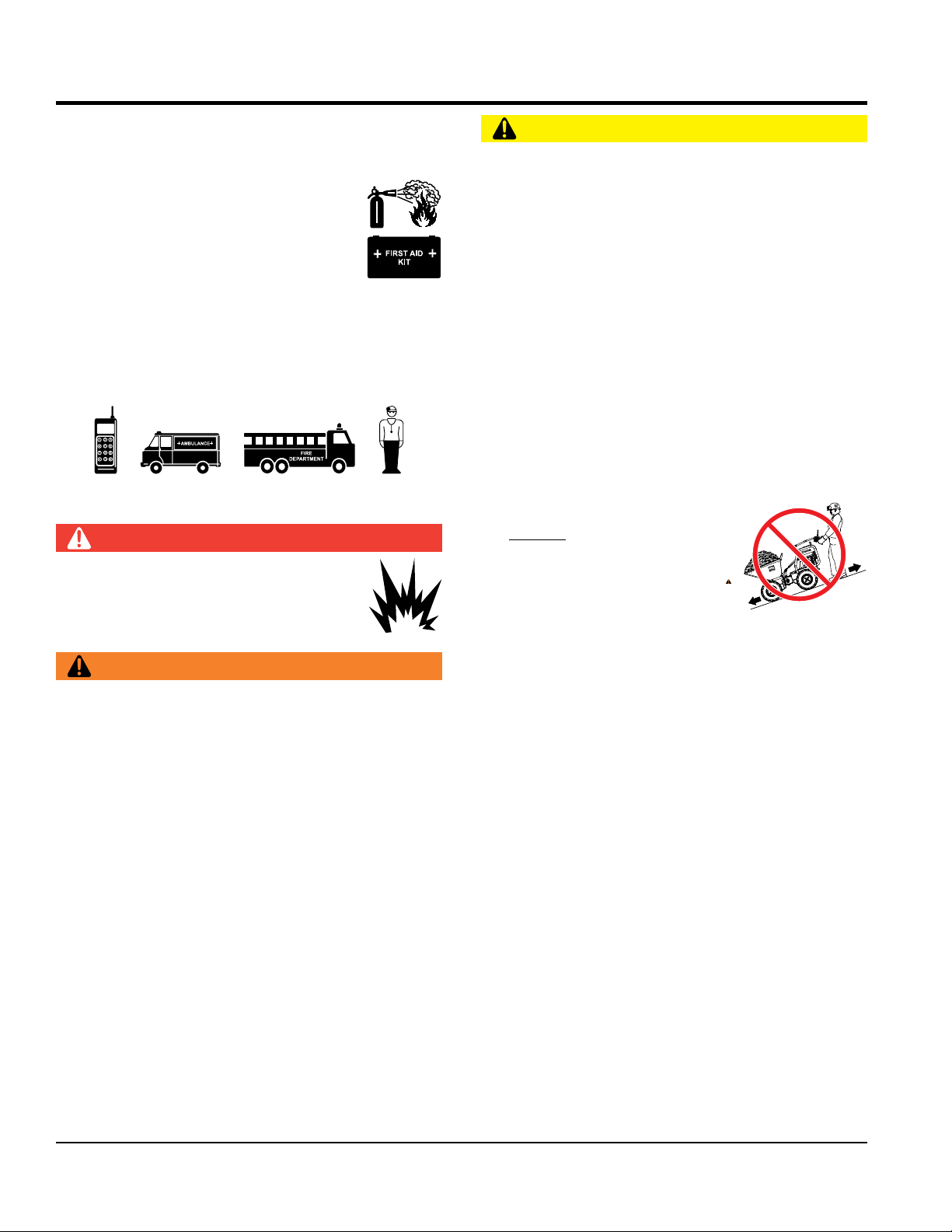
When parking on a slope, position the TuffTruk at a right
angle to a slope.
When filling or dumping DO NOT exceed payload
capacity of TuffTruk.
ALWAYS be aware of traveling conditions. Reduce load
if necessary.
DO NOT activate dump mechanism (tub/bucket) if
TuffTruk is facing a down hill slope.
DO NOT stand in front or along side the TuffTruk when
discharging a load.
ALWAYS block the TuffTruk with appropriate blocks when
leaving the TuffTruk parked on a slope.
To prevent unexpected loss of control, DO NOT start
engine on a sloping surface.
Ensure that the speed control levers works freely and
returns to the stop position. DO NOT start electric motor
unless speed control linkage is working properly.
Make sure that the tires are inflated to the manufacturer’s
recommended tire pressure.
NEVER operate the TuffTruk with bad or worn tires.
ALWAYS replace defective tires with new ones.
Avoid sudden stops and starts and changes in direction.
Operate the controls smoothly. DO NOT jerk the steering
or any other controls.
NEVER attempt to engage the controls except from the
operator’s position.
NEVER operate or tow the TuffTruk in traffic or on public
roads.
ALWAYS keep the machine in proper running condition.
Fix damage to machine and replace any broken parts
immediately.
The entire TuffTruk (tub, shroud, wheels, etc.) should be
cleaned after every use. Make sure there is no buildup of
concrete, grease, oil or debris on the machine.
ALWAYS store equipment properly when it is not being
used. Equipment should be stored in a clean, dry location
out of the reach of children and unauthorized personnel.
BATTERY SAFETY
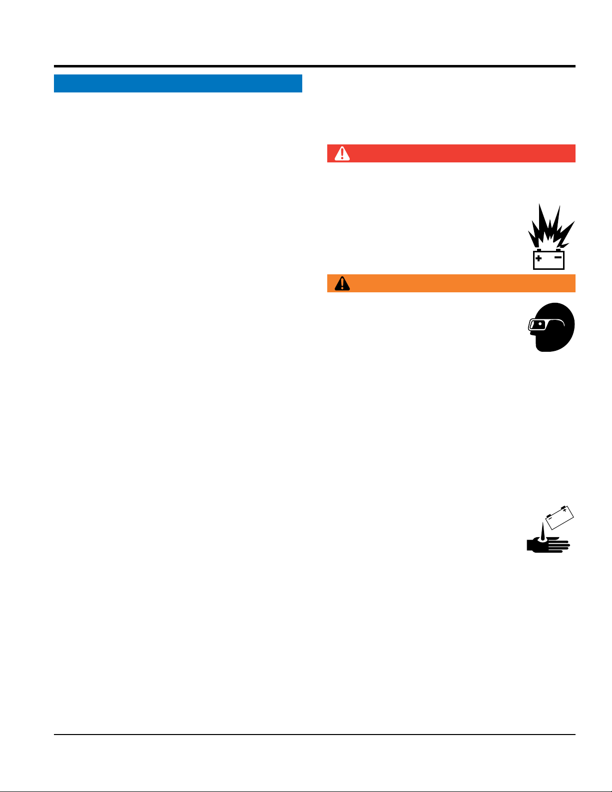
DANGER
DO NOT
drop the battery. There is a possibility that the
battery will explode.
DO NOT expose the battery to open flames,
sparks, cigarettes, etc.The battery contains
combustible gases and liquids. If these
gases and liquids come into contact with a
flame or spark, an explosion could occur.
WARNING
ALWAYS wear safety glasses when
handling the battery to avoid eye irritation.
The battery contains acids that can cause
injury to the eyes and skin.
Use well-insulated gloves when picking up
the battery.
ALWAYS
keep the battery charged. If the battery is not
charged, combustible gas will build up.
DO NOT
charge battery if frozen. Battery can explode.
When frozen, warm the battery to at least 61°F (16°C).
ALWAYS
recharge the battery in a well-ventilated
environment to avoid the risk of a dangerous concentration
of combustible gases.
If the battery liquid (dilute sulfuric acid)
comes into contact with clothing or skin,
rinse skin or clothing immediately with
plenty of water.
If the battery liquid (dilute sulfuric acid) comes into
contact with eyes
, rinse eyes immediately with plenty
of water and contact the nearest doctor or hospital to
seek medical attention.