7
Operator Safety
Training
Operators must be properly trained in the correct use of this machine before taking part in any
operation. It is up to the facility to determine guidelines based on these instructions for use. It is
up to the organization’s management structure to implement training programs, written
procedures, and supervision that are compliant with local regulations.
Operation
All persons operating this machine need to fully read this instruction manual and familiarize
themselves with the machine before operation. The machine is built to have 1-2 operators
standing at the front of the machine feeding material through the die plate.
▪ WARNING – This product is a piece of power equipment that if used in ways other than
described by this instruction manual can result in operator injury or even death.
▪ WARNING – Keep all shields, guards and safety devices installed and in proper working
order at all times.
▪ WARNING – Keep all hands, feet and clothing away from power driven parts.
▪ WARNING –This machine is capable of pulling body parts, hair, clothing, gloves, etc.
into the feed holes of the installed Die Plate. Use extreme caution to prevent unintended
items from entering the feed holes of installed Die Plates.
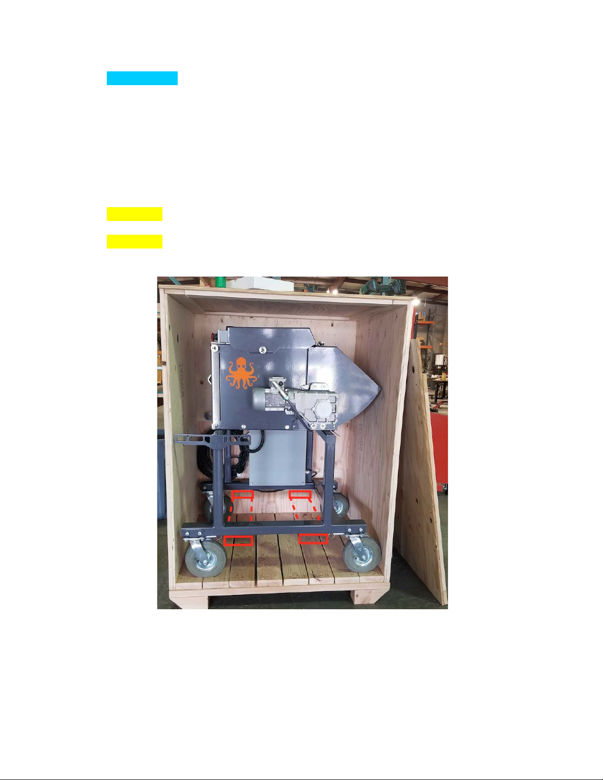
Uncrating
Upon receipt of the Cluster Bucker, freight must be inspected upon arrival. If you suspect
damage, it is essential to document by taking photos of the packaging issues/damage and
notating DAMAGE on the proof of delivery (POD) prior to signing. Do not sign for the shipment
until you have thoroughly inspected the packaging and contents.
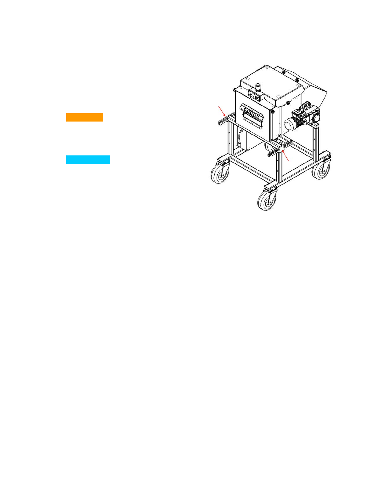
The Cluster Bucker crate will have one side panel that is held closed with wood screws. While
supporting the panel, remove all screws from the outer perimeter of the crate. Once screws are
removed, set the panel aside.
The Cluster Bucker will be held in place with nylon strapping. Prior to strap cutting, ensure all
individuals nearby are wearing the proper personal protective equipment to guard against
possible flying debris. Also, check that the machine is stable and supported prior to cutting to
prevent injury. Cut the strapping with a sharp knife or scissors in a way that prevents damage to
the machine finish.
▪ WARNING – Proper personal protective equipment is essential for all persons working
around the uncrating and setup of the machine.
▪ CAUTION – Injury could result if proper precautions are not taken to ensure the
equipment is stable during the uncrating process.