MUND CLIMA MH-10-V5 User manual

HU10530 to HU10531
DESHUMIDIFIER MH-V5
Service manual
English
MH-10-V5
MH-20-V5

Service Manual
Table of Contents
Part Ⅰ: Technical Information ............................................................ 3
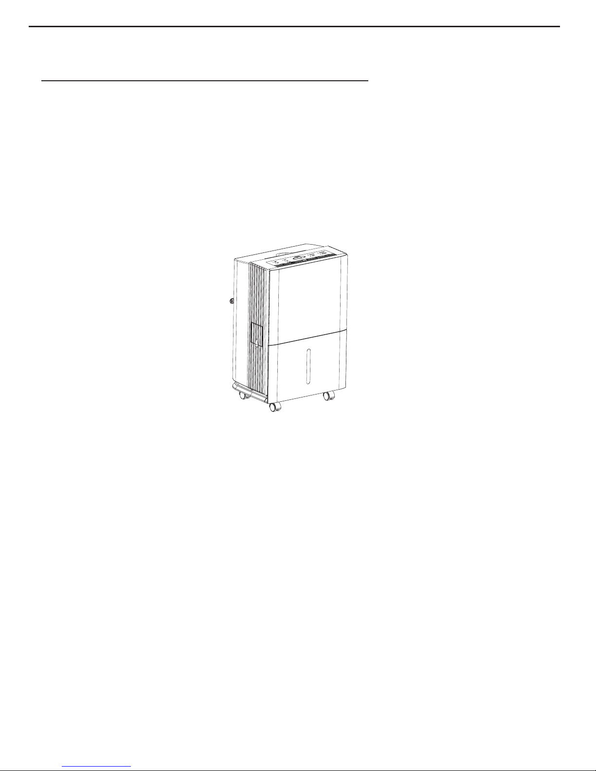
1.Summary ...................................................................................................... 3
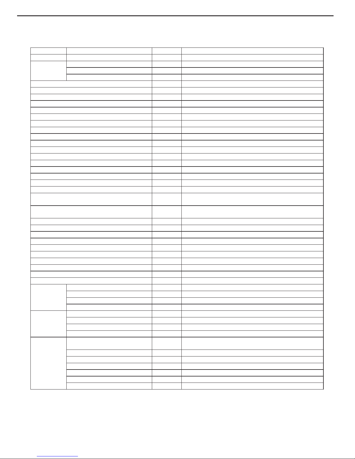
2.Specications ........................................................................................... 4
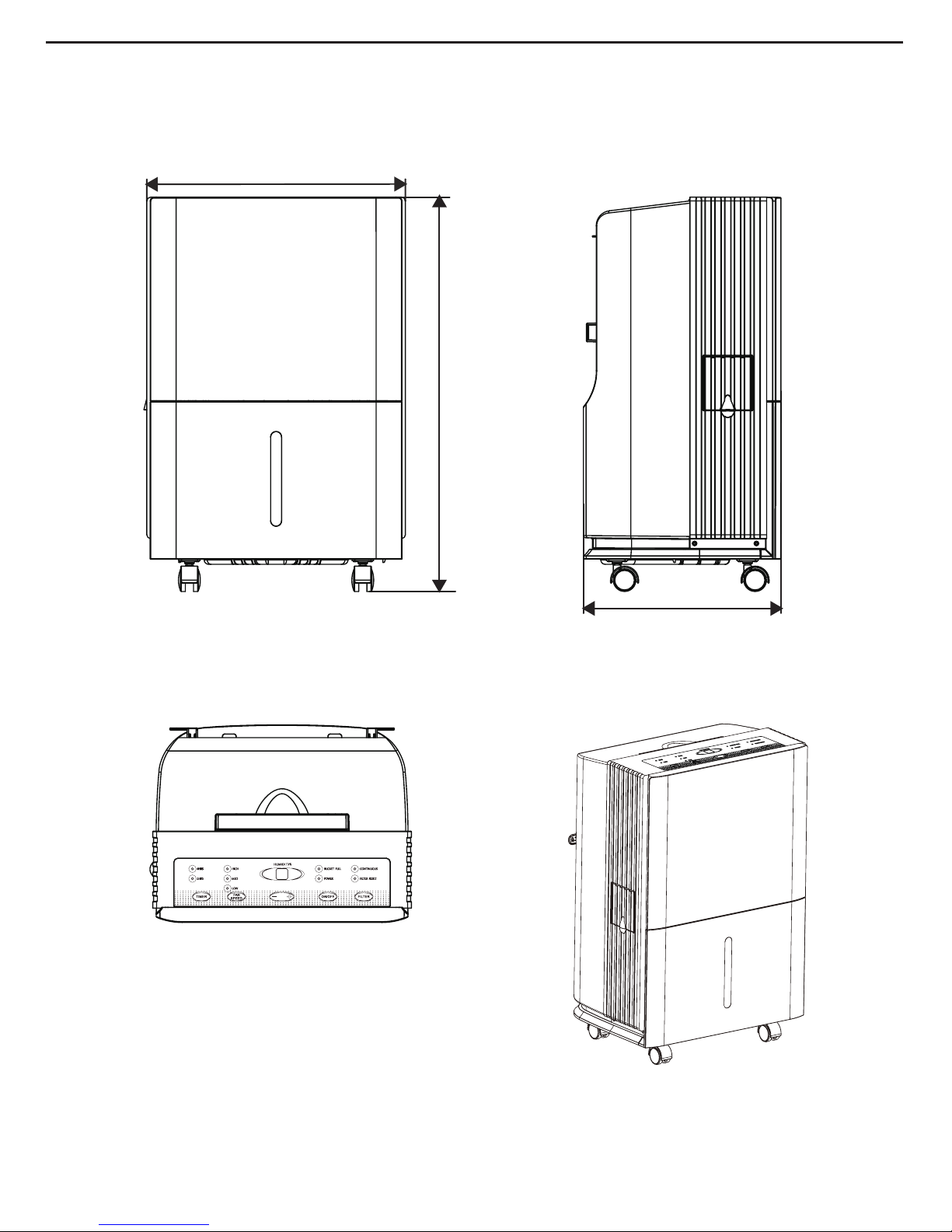
3.Outline Dimension Diagram .............................................................. 6
4.Refrigerant System Diagram ............................................................7
5.Electrical Part ............................................................................................8
5.1 Wiring Diagram ...........................................................................................8
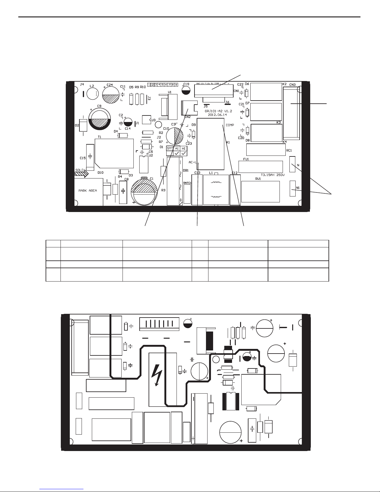
5.2 PCB Printed Diagram ..................................................................................9
6.Function and Control .......................................................................... 11
6.1 Control Panel Instruction ........................................................................... 11
6.2 Introduction of Basic Mode Function ......................................................... 12
Part Ⅱ: Maintenance ............................................................................ 14
7.Notes Maintenance .............................................................................. 14
8.Maintenance ............................................................................................. 15
8.1 Error Code ................................................................................................. 15
8.2 Malfunction Detection Flowchart ............................................................... 16
8.3 Maintenance Method for Common Malfunction ........................................ 18
9.Exploded View and Parts List ........................................................ 20
10.Removal Procedure ........................................................................... 23
Appendix: ...................................................................................................... 30
Appendix 1: Reference Sheet of Celsius and Fahrenheit ............................... 30
Appendix 2: Resistance Table of Temperature Sensor ................................... 31
Appendix 3: Resistance Value Table of Humidity Sensor ............................... 36
2

1.Summary
Part Ⅰ: Technical Information
Models
MH-10-V5
MH-20-V5
Service Manual
3

The above data is subject to change without notice; please refer to the nameplate of the unit.
Model
Product Code CK051024000
Power Supply
Rated Voltage V~ 220-240
Rated Frequency Hz 50
Phases 1
Rated Dehumidifying Volume L/h 0.17
Power Input W 220
Power Current A 1.20
Set Humidity Range % 35~80
Air Flow Volume(H/M/L) m3/h 150/120/100
Fan Motor Speed (H/M/L) r/min 930/800/650
Output of Fan Motor W 6
Fan Motor Capacitor μF 1.0
Fan Type Centrifugal
Diameter Length(DXL) mm Φ180X76.5
Throttling Method Capillary
Fuse A 3.15
Sound Pressure Level (H/M/L) dB (A) 43/41/39
Sound Power Level ((H/M/L) dB (A) 53/51/49
Climate Type T1
Isolation I
Moisture Protection IPX0
Permissible Excessive Operating Pressure for the
Discharge Side MPa 1.7
Permissible Excessive Operating Pressure for the
Suction Side MPa 0.6
Dimension (WXHXD) mm 343X525X262
Dimension of Carton Box (LXWXH) mm 391X310X569
Dimension of Package (LXWXH) mm 394X313X584
Application Area m214
Net Weight kg 13
Gross Weight kg 14.5
Refrigerant R134a
Refrigerant Charge kg 0.08
Bucket Capacity L 4.0/4.6
Control Type Electronic
Evaporator
Form Aluminum Fin-copper Tube
Pipe Diameter mm Φ7
Row-n Gap mm 1-1.3
Coil Length (LXDXW) mm 235X12.7X190.5
Condenser
Form Aluminum Fin-copper Tube
Pipe Diameter mm Φ7
Rows-n Gap mm 1-1.4
Coil Length (LXDXW) mm 235X12.7X190.5
Compressor
Compressor Manufacturer/Trademark Shanghai Hitachi Electrical
Appliances Co.,Ltd/HIGHLY
Model BSA418CV-R1AUA
Type Rotary
Power Input W 213
Overload Protector URP-191-78
L.R.A. A 3.4
Working Current A 1.1
MH-10-V5
2.Specications
Service Manual
4

The above data is subject to change without notice; please refer to the nameplate of the unit.
Model
Product Code CK051023800
Power Supply
Rated Voltage V~ 220-240
Rated Frequency Hz 50
Phases 1
Rated Dehumidifying Volume L/h 0.41
Power Input W 300
Power Current A 1.5
Set Humidity Range % 35~80
Air Flow Volume(H/M/L) m3/h 180/160/140
Fan Motor Speed (H/M/L) r/min 950/860/740
Output of Fan Motor W 7
Fan Motor RLA A 0.13
Fan Motor Capacitor μF 1
Fan Type Centrifugal
Diameter Length(DXL) mm Φ180X76.5
Throttling Method Capillary
Fuse A 3.15
Sound Pressure Level (H/M/L) dB (A) 45/43/41
Sound Power Level ((H/M/L) dB (A) 55/53/51
Climate Type T1
Isolation I
Moisture Protection IPX0
Permissible Excessive Operating Pressure for the
Discharge Side MPa 1.7
Permissible Excessive Operating Pressure for the
Suction Side MPa 0.6
Dimension (WXHXD) mm 343X525X262
Dimension of Carton Box (LXWXH) mm 391X310X569
Dimension of Package (LXWXH) mm 394X313X584
Application Area m228
Net Weight kg 15.5
Gross Weight kg 17
Refrigerant R134a
Refrigerant Charge kg 0.2
Bucket Capacity L 4.0/4.6
Control Type Electronic
Evaporator
Form Aluminum Fin-copper Tube
Pipe Diameter mm Φ7
Row-n Gap mm 1-1.3
Coil Length (LXDXW) mm 235X12.7X190.5
Condenser
Form Aluminum Fin-copper Tube
Pipe Diameter mm Φ7
Rows-n Gap mm 2-1.4
Coil Length (LXDXW) mm 235X12.7X190.5
Compressor
Compressor Manufacturer/Trademark RECHI PRECISION CO.,LTD/
RECHI
Model 39E073HR&F^YA
Type Rotary
Power Input W 300
Overload Protector UP3-017
L.R.A. A 5.5
Working Current A 1.4
MH-20-V5
Service Manual
5

Service Manual
262
525
343
unit:mm
3.Outline Dimension Diagram
6

Service Manual
4.Refrigerant System Diagram
air in
evaporator
capillary
condenser
fan motor
air out
compressor
Dehumidifying principle of dehumidier:
When temperature is decreased to the temperature point of dew, water vapor in humid air will condensate. Dehumidier is
dehumidifying the air by using this principle.
During operation of the system, air will pass through evaporator and condenser in turn and then be discharged due to centrifugal
blade. When the air is passing through evaporator, refrigerant will absorb the heat in air to let its temperature decrease to the
temperature point of dew, water vapor in air will condensate. Condensate water comes into water tank through water tray, or is
discharged directly through drainage hose. The saturated low-temperature air passed through the evaporator will absorb the heat
when owing along the condenser, and then become the dry air. Under normal condition, the nearby air will become warm during
operation of dehumidier.
7

Symbol Symbol Color Symbol Symbol Color Symbol Name
WH White GN Green COMP Compressor
YE Yellow BN Brown Grounding wire
RD Red BU Blue / /
YEGN Yellow/Green BK Black / /
VT Violet OG Orange / /
5.Electrical Part
5.1 Wiring Diagram
●Instruction
These circuit diagrames are subject to change without notice ,please refer to the one supplied with the unit.
PE
YEGN
CN4
SENSOR
ST
HUMIDITY
AC-L
YEGN
C1
C
RD
YEGN(GN)
BU(WH)
BN(BK)
CN1
AP2
CN1
CN3
AP1
L
N
COMP.
M
WATER LEVEL SWITCH
N1
PE
POWER
FAN
MOTOR
PE
YEGN
PE
COMP
SA
COM NO
BU BN
CN2
K1
N
PE
TUBE
RT1
TUBE
TEMP.SENSOR
ELECTRIC BOX
C2
YE BU
BU
R
S
Service Manual
8

Service Manual
Silk Screen on Main Board
5.2 PCB Printed Diagram
● Top view
● Bottom view
No. Name Description No. Name Description
1Needle stand of board
connection wire Connect to display board 4 Interface of neutral wire Connect to neutral wire
of commercial wire
2 Needle stand of fan Connect to fan 5 Interface of compressor Connect to compressor
3 Interface of live wire Connect to live wire of
commercial wire 6Needle stand of water
blow protection switch
Connect to water blow
protection switch
6 3 5
4
1
2
9

Silk Screen on Display Board
● Top view
● Bottom view
No. Name Description No. Name Description
1Needle stand of pipe
temperature sensor
Connect to pipe temperature
sensor 12 Set humidity button Increase set humidity
button
2 Timer 4H indicator Timer 4H indicator is on 13 Set humidity button Decrease set humidity
button
3 Med fan step indicator Med fan step indicator is on 14 Fan speed button Preset fan speed button
4 High fan step indicator High fan step indicator is on 15 Low fan step indicator Low fan step indicator is
on
5 Dual-8 digital display tube Display ambient humidity or
preset temperature 16 Timer button Preset timer time button
6 Power supply indicator Power supply indicator is on 17 Timer 2H indicator Timer 2H indicator is on
7
Neddle stand of humidity
and ambient temperature
sensor
Connect to humidity and
ambient temperature sensor / / /
8 Connection wire of board Connect to mainboard / / /
9 Filter reset button Filter reset button / / /
10 Remind indicator of
cleaning lter
Remind indicator of cleaning
lter is on / / /
11 On/off button On/off button / / /
1
23 4 5 6
7
8
9101112
1314151617
Service Manual
10

Service Manual
6.Function and Control
6.1 Control Panel Instruction
Clean the Filter
indicator light
Continuous operation on
indicator light
Bucket full light indicates
bucket needs to be emptied
or it is not in the proper place.
4 hour or 2 hour
delay on/off
indicator lights High,Mid and Low fan
indicator lights
Power On
indicator light
1.ON/OFF Pad
Press to turn the dehumidier on or off.
2.FILTER Pad
After 250 hours of operation, the Clean the Filter indicator light will glow to remind you to clean the lter. Remove the lter and
clean it. Press to turn off the Clean the Filter light. See the Care and Cleaning section.
3.Humidity Set Control Pads
The humidity level can be set within a range of 80% RH (Relative Humidity) to 35% RH (Relative Humidity) in 5% reduce or at
CO for continuous operation.
NOTE: If CO (Continuous) is selected, the dehumidier will operate continuously at its maximum dehumidication settings if
attached to a hose to drain or until the bucket is full.
For drier air, press the - pad and set to a lower percent value (%).
For damper air, press the + pad and set to a higher percent value (%).
When you first use the dehumidifier, set the humidity control to 45% or 50%. Allow at least 24 hours for the dehumidifier to
achieve the humidity level. If you still have damper air than desired, set the humidity level to a lower setting or select Continuous
for maximum dehumidication.
This unit has 3-min lag due to the device for protecting circuit .In order to prolong the compressors working life, the compressor
will not start until the unit has run for 3 minutes.
4.Display
Shows the set % humidity level while setting, then shows the actual (+/– 5% accuracy) room % humidity level.
5.FAN SPEED Pad
Controls the fan speed. Press to select High or Mid or Low fan speed.
Set the fan control to High for maximum moisture removal. When the humidity has been reduced and quiet operation is preferred,
set the fan control to Mid or Low.
6.TIMER Pad
If unit is turned on and running in timer mode for 2hr or 4hr,can turn off the unit. When unit stand by and running in timer mode
for 2hr or 4hr can turn on the unit.
Other Features
BUCKET FULL Light
Glows when the bucket is ready to be emptied, or when the bucket is removed or not replaced in the proper position.
Alarm
If the bucket is full or missing for more than three minutes, an alarm will sound for about 10 seconds to remind you to empty and
replace the bucket.
Auto Shut Off
The Water Level Control Switch shuts off the dehumidier when the bucket is full, or when the bucket is removed or not replaced
in the proper position.
Auto Defrost
When frost builds up on the evaporator coils, the compressor will cycle off and the fan will continue to run until the frost
disappears.
Power Outage
In the case of a power outage or interruption, the unit will automatically re-start, in the settings last used, after the power is
restored.
11

6.2 Introduction of Basic Mode Function
1. Basic Function
1) Dry conditions and process
a. When HUMIDITYpreset≤HUMIDITYamb.-5%, compressor and fan will run.
b. When HUMIDITYpreset≥HUMIDITYamb.+5%, compressor stop to run and fan will stop operation after 3min.
c. When DEHUMITYamb.-5%<HUMIDITYpreset<HUMIDITYamb.+5%, when compressor is operation, it will run with condition a; when
compressor stops, it will run with condition b. If under this condition when the unit is on, the compressor is off and fan will stop to run
after 3min delay.
2) Humidity Range
a. 5% is one step, it can be adjusted continuously from CO, 35%-80% (CO stands for dehumidify continuously).
b. Adjust preset temperature by “+” and “-”.
2. Protection Function
(1) Working temperature range
a. Detect the unit after energized, when 2 ℃≤Tamb. ≤45 ℃, the unit is running normally; when Tamb. <2 ℃ or Tamb.> 45 ℃, the
compressor stops, and fan will run with the detected temperature humidity;
b. During operation, when Tamb. <2℃ or Tamb.> 45℃, the compressor stops, and fan will run with the detected temperature humidity;
when 2℃≤Tamb. ≤45℃, the compressor will be started up.
(2) Compressor Protection
a. After energization, under any situation and after compressor stops, it will restart 3min delay at least.
b. Under operation state except temperature sensor malfunction, on/off button, water-blow protection, after compressor starts up, it will
stop after it runs for 3min at least.
(3) Detection for temperature sensor malfunction (Temperature sensor malfunction is AD value≤5 or 250≤AD value)
a. When the unit is energized, it is detected that the ambient temperature sensor is open or short circuit for 30s, compressor and fan
stops, LED indicator is off, buttons are invalid, and nixie tube displays “F1”.
b. It is detected that the pipe temperature sensor is open or short circuit for 30s, compressor and fan stops, LED indicator is off, buttons
are invalid, and nixie tube displays “F2”.
c. When it detected that the humidity sensor is short-circuited for 30s successively, compressor and fan will stop operation. Meanwhile,
LED will be off, buttons are invalid and dual-8 nixie tube will display L1.
d. When theres multiple malfunctions, the error codes will be displayed in turn.
(4) Water blow protection (off switch)
a. The water blow protection will be occurred when the water level of water tank is exceeded. After water blow protection, compressor
stops and fan stops after 3mins. If water blow protection occurred for 3min, the buzzer will stop after it gives out a beep for 10s,
indicator of water blow will blinks and all the buttons are invalid. When the water level or assembly of water tank resume to normal,
signal of water blow protection will cancelled, indicator is off, buzzer stops to give out a beep and resume to normal operation state.
b. When the unit is off, water blow protection is occurred, water blow indicator blinks, compressor and fan stops, all the buttons are
invalid except on/off buttons. When the unit is on, water blow indicator blinks, buzzer will not give out a beep, compressor and fan
stops.
3. Other Functions
(1) Power-off memory
Upon power failure, the unit after power recovery will automatically start to run according to memory content.
(2) Nixie tube display
a. When the unit is running, it will display current humidity, preset temperature will be adjusted by “+” or “-”, it will resume current
humidity after the set is nished for 5s.
b. Under any situation and the temperature sensor is malfunction, nixie tube displays “F1” , “F2” or “L1”, timer lamp,
continuous humidity lamp, fan speed lamp and lter lamp will not display.
(3) Front panel button
On/off : turn on/off the unit
Timer: use for timer setting
+: Adjust humidity
-: Adjust humidity
Fan speed: adjust fan speed
Filter: adjust lter function
(4) LED indicator
Continuous humidity lamp: “CON” lamp is on, nixie tube display “CO”;
Power supply indicator: it is on after the unit is energized;
2H timer lamp: the lamp is on after setting 2H timer;
4H timer lamp: the lamp is on after setting 4H timer;
High fan speed indicator: the lamp is on after setting fan is in high speed.
Med fan speed indicator: the lamp is on after setting fan is in med speed.
Low fan speed indicator: the lamp is on after setting fan is in low speed.
Service Manual
12

Service Manual
Filter cleaning lamp: the lamp is on when the operation time of fan reaches to 250h totally.
Water blow protection lamp: the lamp blinks if water blow protection is occurred.
(5) Timer control
2h or 4h timer can be set, set timer off when the unit is on, set timer on when the unit is off. The buzzer will not give out a beep after
timer time reaches. Timer time is every 30min which recorded by memory function (read-in memory slug).
(6) Buzzer
When the controller is energized or receives any command or signal from the buttons or the remote controller, the buzzer will give
out a beep.
(7) Filter alarm function
a. After fan runs for 250h totally, lter lamp is on to remind customer clean lter.
b. When the unit is off, the lter lamp is off; the lter time can not be clearance when the unit is off.
13

7.Notes Maintenance
Electrical Safety Precautions:
Safety Precautions:
Important!
Please read the safety precautions carefully
before maintenance:
The following contents are very important for installation
and maintenance.
Please follow the instructions below.
●The maintenance must accord with the instructions.
●Comply with all national electrical codes and local
electrical codes.
●Pay attention to the warnings and cautions in this
manual.
●Be caution during maintenance. Prohibit incorrect
operation to prevent electric shock and other accidents.
1. Cut off the power supply before maintenance.
2. Specialized circuit must be applied; prohibit sharing the
same circuit with other electric appliances; protection switch
must be installed.
3.Have the unit adequately grounded. The grounding wire cant
be used for other purposes.
4. The live wire, neutral wire and grounding wire of power sup-
ply must be corresponding to the live wire, neutral wire and
grounding wire of the dehumidier.
5. The power cord cant be pressed by hard objects.
6. If the power cord or connection wire is not long enough,
please get the specialized power cord or connection wire from
the manufacture or distributor. Prohibit prolong the wire by
yourself.
7. Replace the fuse with a new one of the same specication if
it is burnt down; dont replace it with a cooper wire or conduct-
ing wire.
8. Use the power supply with same voltage and frequency as
shown in rating label.
9. Do not pull out the power plug when the unit is operating to
avoid damaging the circuit.
10. Do not place anything at the top of dehumidier; ensure the
air outlet or air inlet is not blocked; do not use the unit near
wall and curtain.
11. Do not use heating equipment around the unit.
1. Avoid contact between refrigerant and re as it generates
poisonous gas. Recycle the refrigerant inside the unit
completely before welding pipes.
2. Apply specified refrigerant only. Never have it mixed
with any other refrigerant. Never have air remain in the
refrigerant line as it may lead to rupture or other hazards.
3.If refrigerant is leaking seriously, it may cause suffocation
or explosion. When using the combustible refrigerant,
please put the unit at ventilated place.
4. Never touch the refrigerant piping or compressor without
wearing glove to avoid scald or frostbite.
Warnings
Refrigerant Safety Precautions:
Improper installation may lead to re hazard explosion,
electric shock or injury.
Part Ⅱ: Maintenance
Service Manual
14

No. Malfunction
Name Nixie tube display Unit status Possible Causes
1
Malfunction of
ambient temp.
sensor
F1
The compressor and fan
stop; buttons are invalid
1. The wiring terminal between ambient temperature
sensor and main board is loosened or poorly
contacted;
2. Theres short circuit due to trip-over of the parts on
controller;
3. Ambient temperature sensor is damaged (Please
check it by referring to the resistance table for
temperature sensor);
4. Main board is broken.
2
Malfunction
of tube temp.
sensor
F2
1. The wiring terminal between evaporator temperature
sensor and main board is loosened or poorly
contacted;
2. Theres short circuit due to the trip-over of the parts
on controller;
3. Evaporator temperature sensor is damaged
(Please check it by referring to the resistance table for
temperature sensor);
4. Main board is broken.
3
Malfunction
of humidity
sensor
L1
1. Humidity sensor is short-circuit;
2. Humidity sensor is broken;
3. Display board is broken.
4
Freon-lacking
protection
F0 The compressor stop
1. Refrigerant is leaking
2. System is blocked
8.Maintenance
8.1 Error Code
Service Manual
15

Start
Insert the temperature
sensor tightly
yes
M alfunction is
eliminated.
Make the parts upright
yes
Malfunction is
eliminated .
Replace the controller with
one of the same model
End
no
no
no
no
yes yes
Malfunction is
removed .
no
yes
yes
no
Is the wiring
terminal between temperature
sensor and the controller loosened or
poorly contacted?
Is there short circuit due to trip over
of the parts?
Is the temperature
sensor normal according to the
Resistance Table?
Replace it with a
temperature sensor
of the same model
9.3.1 F1/F2 Malfunction
1. Malfunction of temperature sensor F1, F2
8.2 Malfunction Detection Flowchart
Service Manual
16

Service Manual
2.Malfunction of humidity sensor L1
Trouble shooting for malfunction
of humidity sensor
Humidity sensor is not
connected well with mainboard yes
yes
yes
yes
yes
yes
no
no
no
no
no
no
End
Check the connection
Is malfunction
eliminated?
Is malfunction
Is malfunction
eliminated?
eliminated?
Replace the display board
with the same model
Replace the humidity
sensor board
Is the humidity
sensor normal according to the
Resistance Table?
Eliminate short
circuit phenomenon
The foot of humidity sensor
is short-circuit or the display board
is short circuit
17

8.3 Maintenance Method for Common Malfunction
1.The Unit Cant Start Up
Possible causes Discriminating method (dehumidier status) Troubleshooting
No power supply, or poor
connection for power plug
After energization, operation indicator isnt bright
and the buzzer cant give out sound
Conrm whether its due to power failure. If yes,
wait for power recovery. If not, check power
supply circuit and make sure the power plug is
connected well.
Poor connection between wiring
terminals
Power indicator is not on after the unit is
energized
Check the circuit according to wiring diagram
and connect wire properly; ensure each wiring
terminal contact rmly
There is electric leakage in the
unit
Circuit breaker jump off immediately after the unit
is energized
Make sure the unit is properly grounded;
Make sure the wiring is correct;
Check if the insulating layer of wires inside the
unit and power cord is in good condition; if the
layer is broken, please replace it.
Placing position of water tank is
not correct. Water is removed or
the water is full.
Wall-full indicator ashes. Make sure the water tank is placed correctly.
2. Poor Dehumidifying Effect
Possible causes Discriminating method (dehumidier status) Troubleshooting
Set humidity is irrational Observe the displayed set humidity Adjust set humidity
Filter is blocked Check the lter to see its blocked Clean the lter
Placing position of water tank is
improper.
Check whether therere obstacles around the
dehumidier blocked the air outlet.
Make sure therere no obstacles around the
dehumidiers.
Refrigerant is leaking Air outlet temperature is lower than normal
temperature during dehumidifying period.
Find out the cause of leakage and solve the
problem; charge refrigerant
Malfunction of capillary
Air outlet temperature is lower than normal
temperature during dehumidifying period. If the
refrigerant isnt leaking, some parts of capillary is
blocked.
Replace capillary
Malfunction of fan Fan cant operate. Refer to point 3 of maintenance method for
details
Malfunction of compressor Compressor cant operate Refer to point 4 of maintenance method for
details
3.Fan Cant Operate
Possible causes Discriminating method (dehumidier status) Troubleshooting
Wrong wire connection, or poor
connection
Check the wiring status according to circuit
diagram
Connect wires according to wiring diagram to
make sure all wiring terminals are connected
rmly
Needle stand of connection wire
between mainboard and display
board is loosened
Check if the needle stand is loosened Reinsert the needle stand rmly
Fan capacitor is broken Test the voltage between two ends of fan
capacitor with universal meter and the value is 0 Replace fan capacitor
Power supply voltage is too low
or too high
Test the power supply voltage with universal
meter and the value is too high or too low Apply voltage regulator
Fan is broken The above situation is normal but the fan does
not operate Repair or replace the fan
Service Manual
18

Service Manual
6. Abnormal Sounds and Vibration
Possible causes Discriminating method (dehumidier status) Troubleshooting
There is abnormal sound in some
parts when just turning on or
turning off the unit
Theres the sound of "PAPA" Normal phenomenon. Abnormal sound will
disappear after a few minutes.
There is abnormal sound of
refrigerant owing when just
turning on or turning off the unit
Water-running sound can be heard Normal phenomenon. Abnormal sound will
disappear after a few minutes.
There is touching sound of foreign
objects or parts inside the unit The unit gives out abnormal sound
Take out the foreign objects; adjust the
position of each part inside the unit; tighten the
connection screws; apply some damping gum
on the touching parts
Abnormal shake of compressor Outdoor unit gives out abnormal sound Adjust the support foot mat of compressor,
tighten the bolts
Abnormal sound inside the
compressor Abnormal sound inside the compressor
If add too much refrigerant during maintenance,
please reduce refrigerant properly. Replace
compressor for other circumstances.
5. Water Leakage
Possible causes Discriminating method (dehumidier status) Troubleshooting
Drainage pipe hasnt been
installed correctly. Water is coming out from indoors. Eliminate the blocking objects inside the
drainage channel.
Possible causes Discriminating method (dehumidier status) Troubleshooting
Wrong wire connection, or poor
connection
Check the wiring status according to circuit
diagram
Connect wires according to wiring diagram to
make sure all wiring terminals are connected
rmly
Compressor relay on the
mainboard is broken or the
compressor needle stand is
loosened
Check if the relay is sucked in cooling mode Replace the mainboard with the same model
Capacity of compressor is
damaged
After tuning on the unit, the unit cant dehumidify.
Use universal meter to measure the resistance
value of two contact points of capacitor. If the
resistance value is too big or o, the capacitor is
damaged.
Replace the compressor
Power voltage is a little low or
high
After turning on the unit, dehumidifying effect is
poor or compressor is turned on or off frequently.
Use universal meter to measure the power supply
voltage directly
The uctuation of voltage is 10% rated power.
If the power is too low or too high, you are
suggested to equip wit voltage regulator.
Coil of compressor is burnt out
There is no dehumidifying effect after turning on
the unit; test the resistance of the wiring poles of
compressor with universal meter; if the resistance
is innite or zero, it means it is broken
Repair or replace compressor
Cylinder of compressor is blocked
The dehumidifying effect is poor after turning on
the unit; the noise of compressor is big and the
compressor is hot
Repair or replace compressor
4. Compressor Cant Operate
19

9.Exploded View and Parts List
123456
11 12 13
17
16
15
14
18 24
32
31
30
8
23
22
21
40
34
37
39
43 42
33
29
26
19
35
36
25
20
27
7910
28
38
44
41
Service Manual
20
Table of contents
Other MUND CLIMA Dehumidifier manuals