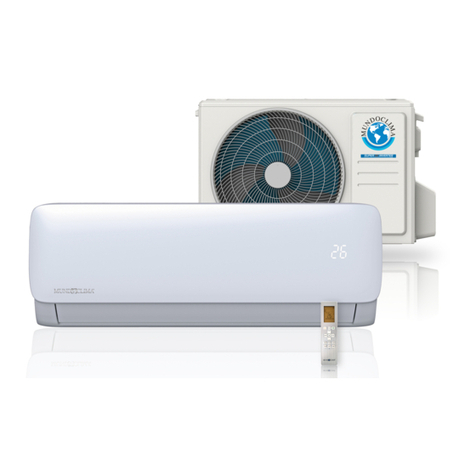
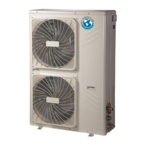
mundoclima MUENR-H6 Series Operating instructions

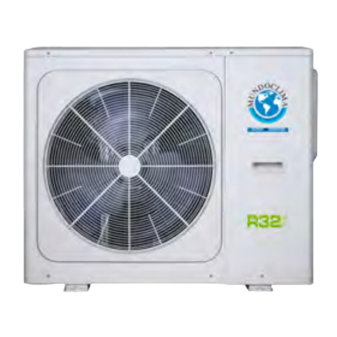
MINI CHILLER INVERTER H6
English
CL25622 to CL25628
MUENR-H6 / MUENR-H6T
(10, 12, 14, 16 kW)
www.mundoclima.com
Installation & Owner's manual
and information requirements

The following symbols are used in this publication and inside the unit:
User
Installer
Assistance
Important
Prohibition
Danger voltage
Danger moving blades
Danger high temperatures
INDEX
70°C
A
I
U
General warnings 2
Fundamental safety rules 2
Description of standard unit 3
Dimensioned drawings 4
Installation 4
Hydraulic connections 6
Electrical connections 9
Operation limits 14
15
17
Checking and starting up the unit 18
Activating and deactivating the unit 18
Shutting down for long periods 23
Routine maintenance 23
Extraordinary maintenance 23
U I A
U I A
I A
I
I
I A
I A
I A
I A
I A
A
U I A
A
A
A
Disposal 25
A
Troubleshooting 25
I A
1
against freezing 14
I A
Protection the water circuit
17
I A
Hydraulic data Important information for the 28
U I A
used refrigerant
Information requirements 29
U I A
Refrigerant circuit 17
I A
of first installation
Failure diagnosis at the moment
Filling with water
Operating characteristics 24
I A
27
I A Specifications

GENERAL WARNINGS
When operating equipment involving the use of electricity
and water,a number of fundamental safety rules must
be observed,namely:
This appliance is not intended for use by persons
(including children) with reduced physical,sensory or
mental capabilities, or lack of experience and
knowledge, unless they have been given supervision
or instruction concerning use of the appliance by a
person responsible for their safety.
Do not touch the unit with bare feet or with wet or
damp parts of the body
Do not carry out cleaning operations without first
disconnecting the system from the electricity supply.
Do not modify safety or regulation devices without
authorisation and instructions from the manufacturer.
Do not pull,detach or twist the electrical cables
coming from the unit,even when disconnected from
the mains electricity supply.
Do not open doors or panels providing access to the
internal parts of the unit without first ensuring that the
mains switch is in the off position.
Do not introduce pointed objects through the air
intake and outlet grills.
Do not dispose of,abandon or leave within reach of
children packaging materials (cardboard, staples,
plastic bags, etc.) as they may represent a hazard.
The chiller appliances are supplied without the main
switch.The power supply to the unit must be
disconnected using a suitable main switch that must
be supplied and installed by the installer.
Respect safety distances between the unit and other
equipment or structures.Guarantee adequate space
for access to the unit for maintenance and/or service
operations;
Power supply:the cross section of the electrical
cables must be adequate for the power of the unit
and the power supply voltage must correspond with
the value indicated on the respective units.All units
must be earthed in conformity with legislation in
force in the country concerned.
Hydraulic connections should be carried out as
indicated in the instructions to guarantee correct
operation of the unit.Empty the water circuit or add
glycol if the unit is not used during the winter.
Handle the unit with the utmost care to avoid damage.
FUNDAMENTAL SAFETY RULES
U AI
U AI
2
This unit is designed to cool/heat water and must be
Incorrect installation,regulation and maintenance or
improper use absolve the manufacturer from all
liability,whether contractual or otherwise,for damage
to people,animals or things.Only those applications
specifically indicated in this list are permitted.
Read this manual carefully.All work must be carried
out by qualified personnel in conformity with
legislation in force in the country concerned.
The guarantee is invalidated if the above instructions
are not respected and if the unit is started up for the
first time without the presence of personnel
authorised by the Company (where specified in the
supply contract) who should draw up a “start-up”
report.
The documentation supplied with the unit must be
consigned to the owner who should keep it carefully
for future consultation in the event of maintenance of
service.
All repair or maintenance work must be carried out
bythe Company’s Technical Service or qualified
personnel following the instructions in this manual.
The air-conditioner must under no circumstances be
modified or tampered with as this may create
situations of risk.Failure to observe this condition
absolves the manufacturer of all liability for resulting
damage.
used in applications compatible with its performance
characteristics, i.e. residential or commercial applications
combined with a fan coil unit, low temperature radiators
and underfloor heating. It should never be used for
underfloor cooling, as doing so may damage the plate
heat exchanger.
DESCRIPTION OF STANDARD UNIT
AI
1
5
7
8
9
10
11
12
13
14
15
16
17
18
19
2
3
4
6
1 Operation panel
2
Water manometer
3 Automatic discharge valve
4
Axial-flow fan
5 Differential pressure switch
6 Condenser
7 Accumulater
8 Security discharge
9 Electric expansive valve
10 Plate heat exchanger
11 Electrical panel
12 High pressure switc
h
13 4-ways valve
14 Expansion tank
15 Pump
16 Low pressure switch
17 Storage tank
18 Compressor
19 Water supply valve
3
These air cooled reverse-cycle chillers with axial-flow fans
operate with refrigerant fluid and are suitable for outdoor
installation.
They are factory tested and on site installation is limited to
water and electrical connections.
STRUCTURE
Panels and base are made from galvanised steel plate
painted with epoxy powder to ensure total resistance to
atmospheric agents.Condensate collection pan as
standard.
COMPRESSORS
Hermetic DC inverter compressor with crankcase heater
and thermal cut-out .
EVAPORATOR
AISI 316 stainless steel plate type evaporator complete
withelectric heater and water flow switch.
Casing lined with anti-condensate closed cell neoprene
cladding.
PUMPS
The units feature a pump with the moving parts in contact
with the water made from corrosion resistant materials,
extra wear ring on the impeller,built-in capacitor for high
starting torque and automatic venting of impeller chamber.
PUMP ASSEMBLY
Pump assembly with expansion tank,safety valve,auto-
water replenishing assembly,pressure gauge and pump.
CONDENSING COILS
Made from copper tubes and high surface area aluminium
fins.Condensing coil protection grills as standard.
FANS
Axial-flow fans.DC motor with built-in thermal cut-out.
Housed in aerodynamic tubes with accident prevention
grill.
Device for operation with low outside air temperatures:
continuous fan rotation speed control via condensing
temperatures transducer.
POWER AND CONTROL ELECTRICAL PANEL
Power and control electrical panel constructed in accor-
dance with IEC 204-1/EN60335-2-40.
OPTIONAL ACCESSORIES AND FUNCTIONS
- Additional pump
- Remote alarm
- Remote shutdown (ON/OFF)
- Remote cooling/heating
- Wire controller (CL92340)
Automatic discharge valve

DIMENSIONED DRAWINGS I
INSTALLATION
CHOICE OF INSTALLATION SITE
Before installing the unit, agree with the customer the site
where it will be installed,taking the following points into
consideration:
-check that the fixing points are adequate to support the
weight of the unit;
-payscrupulous respect to safety distances between the
unit and other equipment or structures to ensure that air
entering the unit and discharged by the fans is free to
circulate.
POSITIONING
Before handling the unit,check the capacity of the lifting
equipment used,respecting the instructions on the
packaging.
Tomove the unit in the horizontal,make appropriate use of
a lift truck or similar,bearing in mind the weight distribution
of the unit.To lift the unit,insert tubes long enough to allow
positioning of the lifting slings and safety pins in the feet on
the unit.
To avoid the slings damaging the unit,place protection
between the slings and the unit.Position the unit in the
site indicated by the customer.Place either a layer of
rubber (min.thickness 10 mm) or vibration damper feet
(optional) between the base and support surface.Fix the
unit,making sure it is level and that there is easy access
to hydraulic and electrical components.If the site of
installation is exposed to strong winds,fix the unit
adequately to the support surface using tie rods if
necessary.If a heat pump unit is being installed,make
sure the condensate is drained using the drain hose
supplied as standard.Prevent leaves,branches or snow
from accumulating around the unit.These could reduce
the efficiency of the unit.
I
1327
900
970
600
348
320
400
360
4

zSince the gravity center of the unit is not at its physical center, so please be careful when lifting it with a sling.
zNever hold the inlet of the outdoor unit to prevent it from deforming.
zDo not touch the fan with hands or other objects.
zDo not lean it more than 45ć, and do not lay it sidelong.
zMake concrete foundation according to the specifications of the outdoor units.
zFasten the feet of this unit with bolts firmly to prevent it from collapsing in case of earthquake or strong wind.
>60cm
Fix with bolt
Single unit installation
>300
>600
>300
>
2000
(Wall or obstacle)
Maintain
channel
Air outlet
Air inlet
A
ir inlet
Parallel connect two units or above
>600
>2000
>300
Parallel connect the front with rear sides
>2000 >500 >3000 >3000 >300
All the pictures in this manual are for explanation purpose only. They may be slightly different from the air conditioner you
purchased (depend on model).The actual shape shall prevail.
INSTALLATION SPACE
5
>2000

HYDRAULIC CONNECTIONS
The choice and installation of components is the responsi-
bility of the installer who should follow good working
practice and current legislation.Before connecting the
pipes,make sure they do not contain stones,sand,rust,
dross or other foreign bodies which might damage the
unit.Construction of a bypass is recommended to enable
the pipes to be washed through without having to discon-
nect the unit (see drain valves).The connection piping
should be supported in such a way as to avoid it weighing
on the unit.It is recommended that the following devices
are installed in the water circuit of the evaporator.
1.Two pressure gauges with a suitable scale (inlet and
outlet).
2.Two vibration damper joints (inlet and outlet).
3.Two gate valves (normal in inlet and calibrating in
outlet).
4.A flow switch (inlet) or a differential pressure switch
(inlet-outlet).
5.Two thermometers (inlet and outlet).
6.An inlet filter as close as possible to the evaporator and
7. An energy-saving water tank.
8. Additional pump.
positioned to allow easy access for routine maintenance.
A hydraulic safety valve shall be mounted in water system,
which should open constantly. 9. The connecting line of flow switch, which mounted
outside the unit, should be connected in series with the
pressure-difference switch, which mounted inside the
unit.
1
Factory Connections Site Connections
A
F
WATER INLET
WATER OUTLET
3
4
7
2
5
6
8
9
10
10
11
12
14
13
11
6
9
9
1Plate Heat Exchange
2 Differential Pressure Switch
3 Automatic Discharge Valve
4 Expansion Tank
5 Auto-watet replenishing
6 Circulating Pump
7 Pressure Gauge
8 Safety Valve
9 Drain/Chemical Washing Valve
10 Flexible Joint
11 Thermometer
12 Calibrating Valve
13 Y-shaped Filter
14 Water Flow Switch
7
7
6
AI

The chillers must be providedwith a filling/top-up
system connected to the return line and a drain cock
in the lowest part of the installation.Installations
containinganti-freeze or covered by specific legisla-
tion must be fitted with hydraulic disconnectors.
The manufactureris not liable for obstruction,
breakage or noise resulting from the failure to install
filters or vibration dampers.Particular types of water
used for fillingor topping up must be treated with
appropriate treatment systems.For reference values,
see the table.
FILLING THE INSTALLATION
-Before filling,check that the installation drain cock is
closed.
-Open all installation and terminal air vents.
-Open the gate valves.
-Begin filling,slowly opening the water filling cock outside
the unit.
-When water begins to leak out of the terminal air vent
valves ,close them and continue filling until the pressure
gauge indicates a pressure of 1.5 bars.
If the installation requires a useful head higher than that
obtained by installing a pump assembly and storage tank,
it is recommended that an additional pump is installed on
the unit. Provided the additional pump installed inside of
unit(only model 12/14/16KW can be installed inside of
unit), the pump must connected close to plate heat
exchanger. Provided the pump installed outside of unit,
the pump shall be connected at water pipe’s outlet.The
pump can be easily installed on the unitby removing the
pump connection pipe (see page 3). Connect to terminal
PL,PN on the electrical panel.
SIZE AND POSITION OF CONNECTIONS
The installation must be filled to a pressure of
between 1 and 2 bars.
It is recommended that this operation be repeated
after the unit has been operating for a number of
hours.The pressure of the installation should be
checked regularly and if it drops below 1 bar,the
water content should be topped-up.
Checkthe hydraulic tightness of joints.
EMPTYING THE INSTALLATION
-Before emptying,place the mains switch in the “off ”
position
-Make sure the installation fill/top-up water cock is closed
-Open the drain cock outside the unit and all the installation
and terminal air vent valves.
If the fluid in the circuit contains anti-freeze,it should
not be allowed to drain freely as it is pollutant.It
should be collected for possible reuse. When draining
after heat pump operation,take care as the water
may be hot (up to 50°).
an all-pole disconnection device which has at least
3mm separation distance in all pole and a residual
current device (RCD) with the rating of above 10mA
shall be incorporated in the fixed wiring according to
the national rule the appliance shall be installed in
accordance with national wiring regulations.
E
F
C
D
B
A
water outlet
auto-water
replenishing orifice
security
water inlet
discharge
Model A
(mm)
B
(mm)
C
(mm)
D
(mm)
E
(mm)
F
(mm)
Water
inlet/outlet
(Ø)
Auto-water
replenishing (Ø)
Security
discharge (Ø)
300 195 155 105 68 105 R5/4 G1/2 G1/2
10 to 16kW
7
(1 1/4")
3 Auto-watet replenishing orifice
4 Water outlet of safety Valve
5 Wire hole
2 Water outlet (1 1/4")
1 Water inlet (1 1/4")

kW is the unit for cooling capacity, L is the unit for (G)
Comfortable type air conditioner
G= cooling capacity×2.6L
Process type cooling
G= cooling capacity×7.4L
In certain occasion (especially in manufacture
cooling process), for conforming the system water
content requirement, it’s necessary to mount a tank
equipping with a cut-off baffle at the system to avoid
water short-circuit, Please see the following schemes:
Error
Recommendation
Error Recommendation
Minimum chilled water flow
The minimum chilled water flow is shown in the below table.
If the system flow is less than the minimum unit flow rate
the evaporator flow can be recalculated, as shown
in the diagram.
DESIGN OF THE STORE TANK IN THE SYSTEM
minimum water flow volume in the formula.
CHILLER WATER FLOW
Evaporator
Recirculation
For minimum chilled water flow rate
Maximum chilled water flow
The maximum chilled water flow is limited by the permitted
pressure drop in the evaporator. It is provided in the below
If the system flow is more than the maximum unit flow rate,
bypass the evaporator as shown in the diagram to obtain
a lower evaporator flow rate.
For maximum chilled water flow rate
Evaporator
Recirculation
Minimum and maximum water flow rates
Item Water flow rate(m3/h)
Model
1.54
1.72 2.11
1.93 2.36
2.24 2.73
1.89
Minimum Maximum
16kW
may cause much sediment, such as furring, sand, and so on.
water equipment before flowing into chilled water system. If
sand and clay settle in the evaporator, circulation of chilled
water may be blocked, and thus leading to freezing accidents;
dness of chilled water is too high, furring may occur easily,
Therefore, the quality of chilled
analyzed before being used, such as PH value,
conductivity, concentration of chloride ion, concentration of
sulfide ion, and so on.
WATER QUALITY CONTROL
When industrial water is used as chilled water, little furring may
occur; however, well water or river water, used as chilled water,
Therefore, well water or river must be filtered and softening
if har
and the devices may be corroded.
water should be
PH
Total hardness
Electrical conductivity less than 200 mV/cm (25C)
Sulfide ion
Chlorine ion
Ammonia ion
Sulfate ion
Silicon
Total iron
Sodium ion
Calcium ion
PH 6 - 8
less than 50 ppm
none
less than 50 ppm
none
less than 50 ppm
less than 30 ppm
less than 0.3 ppm
No requirement
less than 50 ppm
table.
- Before filling, check that the installation drain cock is closed.
- Open all installation and terminal air vents.
- Open the gate valves.
- Begin filling, slowly opening the water filling cock outside
- When water begins to leak out of the terminal air vent valves,
close pressure gauge indicates a pressure of 1.5 bars.
the unit.
FILLING THE INSTALLATION
EMPTYING THE INSTALLATION
- Before emptying, place the mains switch in theŶoffŷposition.
- Make sure the installation fill/top-up water cock is closed.
- Open the drain cock outside the unit and all the installation
and terminal air vent valves.
8
14kW
10kW
12kW

ELECTRICAL CONNECTIONS
The unitary minichillers leave the factory already wired,
and require the installation of an omnipolar thermal
overload switch,a lockable mains disconnecting switch for
the connection to the mains power supply,and the connec-
tion of the flow switch to the corresponding terminals.All
the above operations must be carried out by qualified per-
sonnel in compliance with the legislation in force.
For all electrical work,refer to the electrical wiring diagrams
in this manual.You are also recommended to check:
-that the characteristics of the mains electricity supply are
adequate for the absorptions indicated in the electrical
characteristics table below,also bearing in mind the pos-
sible use of other equipment at the same time.
Power to the unit must be turned on only after
installation work (hydraulic and electrical) has been
completed.
All electrical connections must be carried out by
qualified personnel in accordance with legislation in
force in the country concerned.
Respect instructions for connecting phase, neutral
and earth conductors.The power line should be fitted
upstream with a suitable device to protect against
short-circuits and leakage to earth, isolating the
installation from other equipment.
Voltage must be within a tolerance of ±10% of the
rated power supply voltage for the unit (for three
phase units,the unbalance between the phases
must not exceed 3%).If these parameters are not
respected,contact the electricity supply company.
For electrical connections,use double insulation
cable in conformity with current legislation in the
country concerned
An omnipolar thermal overload switch and a lock-
able mains disconnecting switch,in compliance with
the CEI-EN standards (contact opening of at least
3mm),with adequate switching and residual current
protection capacity based on the electrical data
table shown below,must be installed as near as
possible to the appliance
The devices on the unit must be lockable.
An efficient earth connection is obligatory.Failure to
earth the appliance absolves the manufacturer of
all liability for damage.
In the case of three phase units,ensure the phases
are connected correctly.
Do not use water pipes to earth the unit.
AI
ELECTRICAL PANEL
The electrical panel is located inside the unit at the top of
the technical compartment where the various components
of the refrigerant circuit are also to be found.
To access the electrical panel,remove the front panel of
the unit by undoing the screws.
9
Electrical panel
A
B

10
ELECTRICAL POWER CONNECTIONS
The Specification of Power
The power cord type designation is H07RN-F.
The means for disconnection from a power supply shall be incorporated in the fixed wiring and have an air gap
contact separation of at least 3mm in each active(phase) conductors.
For the functional connection of the unit,bring the power
supply cable to the electrical panel inside the unit and con-
nect it to terminals L-N and respecting the (L) phase,
(N) neutral and earth in the case of single phase units
(220-240V~50Hz),or L1-L2-L3 phases,N neutral and PE
earth in three phase units (380-415V 3N~ 50Hz).
Dealer provides power cord.
For MUENR-10/12-H6: For MUENR-12/14/16-H6T:
1
/*1'
AC220-240V 50Hz
LN
Residual Current
Circuit-breaker
GND
Residual Current
Circuit-breaker
GND
1
&*1'%
$
ABCN
NOTE: The outdoor units must be installed with an Residual Current Circuit-breaker near the power supply
and must be effectively earthed.
For MUENR-10/12-H6:
For MUENR-12/14/16-H6T:
1
&
3
1
2
6
4
5
7
8
*1'
9
10 11
%
$
Additional Wire Controller
ON/OFF
Cooling - Heating
KJR-120F1/BMK-E
Remote
Alarm
Remote Remote
PUMP
AUXILIARY CONNECTIONS
All terminals referred to in the explanations below are to
be found on the terminal board inside the electrical panel
and described as “installer terminals”.
MODEL
POWER
CIRCUIT BREAKER/FUSE (A)
POWER WIRING(mm2)
PHASE
FREQUENCY AND VOLT
40/35
220-240V~, 50Hz 380-415V~, 50Hz
1-PHASE
3x6.0
30/25
3-PHASE
5x4.0
MUENR-10-H6
MUENR-12-H6
MUENR-12-H6T
MUENR-14-H6T
MUENR-16-H6T
1
/
3
1
2
6
4
5
7
8
*1'
9
10 11
Additional Wire Controller
ON/OFF
Cooling - Heating
KJR-120F1/BMK-E
Remote
Alarm
Remote Remote
PUMP

1
2
Additional pump
L
N
220-240V
220-240V
L
N
A1
A2
AC contactor
Main control board
Additional pump terminal (1 - 2) only provides passive
Additional water pump must be controlled by the AC
a. Additional pump
d.Remote alarm
3
4
Main control board
Remote alarm terminal only provides passive
Current passing through the terminal interface
should less than 1.5A, other wise please use
AC contactor to control load indirectly.
b. Remote shutdown (ON/OFF)
5
6
SWITCH
If switch is closed, the unit will be stopped forcibly.
Under this circumstance, anti-frozen protection and other
protecion functions are still effective.
If switch breaks, unit can run normally according settings.
switching signal.
If switch 2 is closed, the unit will shift to heating mode forcibly;
If switch 2 breaks, the unit will shift to cooling mode forcibly.
c.Remotecooling/heating
SWITCH 2
7
8
e. Wire controller (optional CL92340)
9
10 11
PPQE
ʎThe wired controller KJR-120F1/BMK-E is optional.
ʎPlease use 3-core shielded wire to connect the wired
grounded.
parameters and inquiry, can’t be used to set mode and
controller and the shielding layer must be
ʎWhen connecting wired controller, outdoor unit control
used for display which can check
panel is mainly
temperature.
Note:
Note:
Note:
Note:
contactor.
switching signal.
11
KJR-120F1/BMK-E
NOTE
● Remote shutdown and Remote cooling/heating is optional
function.
● Choose this function by DIP switch SW4 or SW3.
(Factory default)
● When the remote control and wire controller used at the same
time, the unit will carry out the last command of arbitrary
terminal.
● Remote shutdown has the highest priority. In the status of
remote shutdown, other controllers can’t start the unit.
ON ON
With remote
control
SW4 SW4
10/12-H6
ON
SW3
12/14/16-H6T 10/12-H6 12/14/16-H6T
ON
SW3
Without
remote
control

WIRING DIAGRAM
MUENR-10/12-H6
12
"PUMP2" and wiring terminal ports provide
only the switch signal.The load should be controlled through
the AC contactor.
""REMOTE ALARM
E9
H0
E4
E5
E6
EA
Eb
P2
P8
P1
P3
P4
P6
P5
EEPROM malfunction
Communication malfunction between
the main controlling chip and IPDU
T3&T4 temperature sensor malfunction
Voltage protection
DC fan motor malfunction
5-minute error for heating mode fan in area A
High pressure protection
Low pressure protection
Outdoor units current protection
Compressor discharge temp. Protection
Condenser high temperature protection
IPM mode protection
Typhoon protection
Two times of E6 protection in 10 minutes
Radiator high temperature protection
PL
C0 Tin temperature sensor malfunction
C1 Tout temperature sensor malfunction
F7 Tb1 temperature sensor malfunction
F8 Tb2 temperature sensor malfunction
Pb
Outdoor units anti-freezing protection
CP
Anti-idling protection of water pump
C8 Flow switch malfunction
CH
High temperature protection in heating mode
12
4
3
5
6
8
7
Tb2 temp. Value
Total capacity requirements
The revised capacity requirements
Cooling/heating temp. set
T3 temp. Value
T4 temp. Value
Tp temp. Value
Fan speed
0- ,1~7-Fan speed
hutdownS
2
11
Tb1 temp. Value
0
9
Tin temp. Value
1
Running mode
0-Shutdown,1-The pump model,2-Cooling,
3-Heating,4-Forced cooling.
10
Tout temp. Value
Checking
No.
Meanings
The normal display
13
17
16
14
15
18
19
20
T6 temp. Value Reserved
Outdoor units current
Power supply voltage AD value
EXV opening
Error 1
Meanings
dF Defrosting
d8 Remote control
Frequency
Error 2
Error 3
Temp. Sensor code
Tin/Tout/Tb1
Tb2/T3/T4
B =4100K , R =10k
25/50 25
Tp
B =3950K , R =5k
25/50 90
Property values
Checking
No.
UVW
U
V
W
2020904A0942
MAIN BOARD
IPM & PFC MODULE
Please use 3-core shielded wire to connect the w
and the shielding layer must be grounded .
ire
controller
BLACK
RED
BLUE
XT1
POWER SUPPLY
Y/G
RED
BLACK
Wire controller
Y/G
1234
3
1
2
6
4
5
9
7
8
GREEN
GREEN
BROWN
BROWN
To XT1
WHITE
GREEN
GREEN
BROWN
BROWN
3456
V
U
W
1234567891011
+12V
ON/OFF
PUMP2
NOTE
XT3
CODE PART NAME
Compressor
CRANK
CT1
XT1
AC current detector
4-WAY
COMP.
EEV. Electric Expansive Valve
Outdoor fan motor
FAN
H-PRO
L-PRO
T3
T4
Tp
Compressor electric heating zone
High pressure switch
Low pressure switch
4-Way valve
Condenser temperature sensor
Outdoor ambient temperature sensor
Comp. Discharge temperature sensor
XT2,XT3
14-Way terminal
CP_HEAT1
Plate Heat Exchanger electric heating zone
FS_HEAT
Tb1
Tin
Tout
Plate heat exchanger anti-freezing
temperature sensor 1
Inlet water temperature sensor of heat exchanger
Outlet water temperature sensor of heat exchanger
Flow switch electric heating zone
F.S.
Flow switch/Exhaust valve
WIRING DIAGRAM (OUTDOOR UNIT)
CAP1,CAP2
CAPACITOR
PTC1,PTC2
L
KM1
AC CONTACTOR
THERMAL RESISTOR
REACTOR
R1,R2
RESISTANCE
ZR1
Voltage Dependent Resistor
3-Way terminal
Plate heat exchanger anti-freezing
temperature sensor 2
Tb2
CT1
N
U
V
W
P
TR
A2
A1
A3
L_OUT
N_OUT
L_IN
N_IN
RED
CT1
123
45
EX_HEAT
CN32
CN31
CN34
CN33
S.V.
BROWN
BROWN
BLUE
BLUE
BLUE
BLUE
CP_HEAT1
FS_HEAT
PUMP1
4-WAY
CRANK
BROWN
BROWN
BROWN
BROWN
BROWN
BROWN
CN35
CN36
CN38
CN19
CN17
FAN-DOWN
FAN-UP
CN41
CN40
6
5
C5N
CN12
CN8
CN9
T4
T3
Tp
H-PRO
L-PRO
CN14
Tout
Tb1
Tin
Tb2
Differential Pressure Switch
CN15
DISPLAY BOARD
EEV.
CN22
RED
WHITE
12
RED
RED
BLACK
BLACK
BLACK
RED
BLACK
YELLOW
YELLOW
BLUE
YELLOW
YELLOW
BLUEBLUE
BLUE
BLUE
RED
BLACK
WHITE
BLACK
EX_HEAT
Exhaust valve electric heating zone
d0 Oil return of compressor
BLACK
RED
BLUE
BLACK
RED
BLUE
Display
CL
Malfunction or Protection
Display
Malfunction or Protection
Low temperature protection in heating mode
A
B
C
D
The wire controller is optional.
C/H
10 11
+12V
PQE
REMOTE
ALARM
Remote cooling/heating
Remote shutdown
8
YELLOW
7 8
YELLOW
Switch setting-Model selection
Reserved
Without remote cooling/heatingWith remote cooling/heating
Reserved

13
MUENR-12/14/16-H6T
E9
H0
E4
E5
E6
EA
Eb
P2
P8
P1
P3
P4
P6
P5
EEPROM malfunction
Communication malfunction between
the main controlling chip and IPDU
T3&T4 temperature sensor malfunction
Voltage protection
DC fan motor malfunction
5-minute error for heating mode fan in area A
High pressure protection
Low pressure protection
Outdoor units current protection
Compressor discharge temp. Protection
Condenser high temperature protection
IPM mode protection
Typhoon protection
Two times of E6 protection in 10 minutes
Radiator high temperature protection
PL
C0 Tin temperature sensor malfunction
C1 Tout temperature sensor malfunction
F7 Tb1 temperature sensor malfunction
F8 Tb2 temperature sensor malfunction
Pb
Outdoor units anti-freezing protection
CP
C8 Flow switch malfunction
CH
High temperature protection in heating mode
Display
Malfunction or Protection
CODE PART NAME
Compressor
CRANK
CT1
XT1
AC current detector
4-WAY
COMP.
EEV. Electric Expansive Valve
Outdoor fan motor
FAN
H-PRO
L-PRO
T3
T4
Tp
Compressor electric heating zone
High pressure switch
Low pressure switch
4-Way valve
Condenser temperature sensor
Outdoor ambient temperature sensor
Comp. Discharge temperature sensor
XT2
14-Way terminal
2-Way terminal
CP_HEAT1
Plate Heat Exchanger electric heating zone
FS_HEAT
Tb1
Tin
Tout
Plate heat exchanger anti-freezing
temperature sensor 1
Inlet water temperature sensor of heat exchanger
Outlet water temperature sensor of heat exchanger
Flow switch electric heating zone
12
4
3
5
6
8
7
Tb2 temp. Value
Total capacity requirements
The revised capacity requirements
Cooling/heating temp. set
T3 temp. Value
T4 temp. Value
Tp temp. Value
Fan speed
0- ,1~7-Fan speed
hutdownS
2
11
Tb1 temp. Value
0
9
Tin temp. Value
1
Running mode
0-Shutdown,1-The pump model,2-Cooling,
3-Heating,4-Forced cooling.
10
Tout temp. Value
Checking
No.
Meanings
The normal display
13
17
16
14
15
18
19
20
T6 temp. Value Reserved
Outdoor units current
Power supply voltage AD value
EXV opening
Error 1
Meanings
dF Defrosting
d8 Remote control
Frequency
Error 2
Error 3
Temp. Sensor code
Tin/Tout/
Tb1/T3/T4
B =4100K , R =10k
25/ 50 25
Tp
B =3950K , R =5k
25/ 50 90
Property values
Checking
No.
F.S.
Flow switch
UVW
U
V
W
202090490066
CAP1
R2
EX_HEAT
BLUE
Y/G
CN47
CN31
CN33
CN32
S.V.
CN17
IC201
CN205
CN19
CN50
CN50
C5N
CN6
CN1
CN9
EEV.
CN22
CN201
T4
T3
Tp
H-PRO
L-PRO
A2
A1
ORANGE
5
4
1
2
3
D1
R1
CAP2
FAN-DOWN
FAN-UP
BLUE
BROWN
WIRING DIAGRAM (OUTDOOR UNIT)
CN36
L1
GND_2
CN36
L1
CN37
L2
CN38
L3
CN30
CN31
CN32
L1
’
L2
’
L3
’
CN19
CN18
GND_1
CN39
N
POWER & FILTER BOARD
MAIN BOARD
UVW
CN2
CN1
PN
CN5
IPM MODULE
BLUE
WHITE(BROWN)
RED
BROWN
RED
(BROWN)
RED
Y/G
BLACK
WHITE
BLACK
ZR1
RED
RED
RED
BLACK
BLACK
RED
BLACK
BLUE
BROWN
BLUE
BLUE
BLUE
BLACK
RED
BLACK
RED
BLUE
ORANGE
RED
L
BLACK
RED
RED
RED
RED
BLUE
IC201
CN250
XT1
POWER SUPPLY
Y/G
Y/G
BLACK
RED
BLUE(BROWN)
BLUE
RED
CAP1,CAP2
CAPACITOR
PTC1,PTC2
L
KM1
AC CONTACTOR
THERMAL RESISTOR
REACTOR
R1,R2
RESISTANCE
ZR1
Voltage Dependent Resistor
PTC1
PTC2
RED BLUE
BLACK
CN14
Tout
Tb1
Tin
Tb2
Differential Pressure Switch
BLUE
CP_HEAT1
FS_HEAT
PUMP1
4-WAY
CRANK
BROWN
BROWN
BROWN
BROWN
BROWN
BROWN
1234
CN34
CN35
CN49
CN38
CN37
CN40
CN20
DISPLAY BOARD
GREEN
GREEN
BROWN
BROWN
XT1
WHITE
GREEN
GREEN
BROWN
BROWN
1234
XT2
V
U
W
NOTE
XT3
XT3
3-Way terminal
Plate heat exchanger anti-freezing
temperature sensor 2
Tb2
CN30
EX_HEAT
Exhaust valve electric heating zone
Anti-idling protection of water pump
d0 Oil return of compressor
Please use 3-core shielded wire to connect w ,
and the shielding layer must be grounded .
ire controller
RED
BLACK
CL
Low temperature protection in heating mode
Display
Malfunction or Protection
A
B
C
D
The wire controller is optional.
3
1
2
6
4
5
9
7
8
10 11
Wire controller
1234567891011
+12V
ON/OFF
PUMP2
C/H
+12V
PQE
REMOTE
ALARM
Remote cooling/heating
Remote shutdown
"PUMP2" and wiring terminal
ports provide only the switch signal.
The load should be controlled through the AC contactor.
""REMOTE ALARM
YELLOW
Switch setting-Model selection
Reserved
Without remote cooling/heatingWith remote cooling/heating
Reserved

14
Air conditioner operating conditions
For proper performance, run the air conditoner under the following temperature conditions
If air conditioner is used beyond the above conditions, safely protection features may come into operation
Thermal head min.- max. 4-6
Water circuit pressure (bars) 1-3
Max.storage temperature 55
Water and glycol solutions used as a thermal During winter leaving the unit unused, please drain
water out completely from unit if no antifreeze were
charged into pipeline, or keep power on(at standby
or off status) and ensure that water is contained
inside of unit.
When ambient temperature lower 5 running
cooling mode must be charged antifreeze. Refer to
upper parameters for the charged volume.
vector in the place of water reduce the performance
of the unit. Multiply the performance figures by the
values given in the following table.
FOULING FACTORS
The performance data given refer to conditions with clean
evaporator plates (fouling factor=1).For different fouling
factors,multiply the figures in the performance tables by
the coefficient given in the following table.
OPERATION LIMITS
AI
Outdoor temperature: -5đ~đ
Cooling operation Water outlet temperature: 4đ~đ
Outdoor temperature: -15đ~đ
Heating operation
If air conditioner is used beyond the above conditions, safely protection features may come into operation
Note: When the outdoor temperature is too low, the unit in standby mode will activate frost protection, forced to run
pumps or forced heating operation to protect the unit water system.
IG M
DELIVERY WATER TEMPERATURE
OUTSIDE AIR TEMPERATURE
35 54
-15
0
27
t(°C)
t(°C)
40
CG M
DELIVERY WATER TEMPERATURE
OUTSIDE AIR TEMPERATURE
4 7 15 20
-5
35
46
t(°C)
t(°C)
Water outlet temperature: 30ºC~54ºC
Cooling capacity
modification
Power
modification
Water
resistance
Water flow
modification
0 1.000 1.000 1.000 1.000 0.000
10 0.94 0.99 1.11 1.019 -4.000
20 0.973 0.995 1.26 1.051 -9.000
30 0.965 0.992 1.42 1.092 -16.000
40 0.960 0.99 1.791 1.145 -23.000
50 0.950 0.93 2.100 1.200 -37.000
Modification coefficient
Quality of
glycol/%
Freezing
point/ć
0 1.000 1.000 1.000 1.000 0.000
10 0.976 0.996 1.071 1.000 -3.000
20 0.961 0.992 1.19 1.016 -7.000
30 0.94 0.9 1.30 1.034 -13.000
40 0.93 0.94 1.72 1.07 -22.000
50 0.925 0.975 2.150 1.125 -35.000
Modification coefficient
Cooling capacity
modification
Power
modification
Water
resistance
Water flow
modification
Quality of
glycol/%
Freezing
point/ć
If no glycol is added, the water must be drained out when there is a
power failure.
PROPYLENE GLYCOL
ETHYLENE GLYCOL
PROTECTION THE WATER CIRCUIT AGAINST FREEZING
AI

0.0
10.0
20.0
30.0
40.0
50.0
60.0
70.0
80.0
External Stac Pressure (KPa)
Flow (m3/h)
Ⅲ
Ⅱ
Ⅰ
f1 capacity correction factor
fk1 compressor power input correction factor
4.4 x 10⁻⁵
0.86 x 10⁻⁴
1.72 x10⁻⁴
-
0.96
0.93
-
0.99
0.98
-
0.99
0.98
Fouling factors
(m2°C/W) f1
Evaporator
fk1 fx1
If the total water volume in the system is less than the
value in the table above, the additional water tank is
necessary in order to avoid the compressor On and Off
frequently.
The minimum size of the water tank is calculated as:
Size of additional water tank(L) = Minimum water
volume(L) - Actual water volume(L)
HYDRAULIC DATA
I A
USEFUL PUMP HEAD CURVES (10 to 16 kW)
(*) To obtain the useful head of the installation,subtract the
pressure drop of the plate heat exchanger.
Constant speed I,II.III
p/kPa
60
40
20
0
0
0
0
40
0012 3 4
P 1/W
0.2 0.4 0.6 1.0 1.2 Q/l/s
Q/m3/h
16 Q/lgpm
1234
0
2
4 12
4
6
4640 1/min
2970 1/min
1270 1/min
Max.
H/m
RS25/7.5 RKC
1~230V-Rp1 1/4
Q/m3/h
15
HEAT EXCHANGER PRESSURE DROP (WATER SIDE)
MUENR-10-H6
MUENR-12-H6 / MUENR-12-H6T
0.0
10.0
20.0
30.0
40.0
50.0
60.0
70.0
80.0
External Stac Pressure (KPa)
Flow (m3/h)
Ⅲ
Ⅱ
Ⅰ
MUENR-14-H6T
0.0
10.0
20.0
30.0
40.0
50.0
60.0
70.0
80.0
External Stac Pressure (KPa)
Flow (m3/h)
Ⅲ
Ⅱ
Ⅰ
fx1 total power input correction factor

16
MUENR-16-H6T
0.0
10.0
20.0
30.0
40.0
50.0
60.0
70.0
80.0
External Stac Pressure (KPa)
Flow (m3/h)
Ⅲ
Ⅱ
Ⅰ
PUMP LED DIAGNOSIS AND SOLUTIONS
The pump has an LED operating status display. This makes it easy for the technician to search for the cause of a fault in the heating system.
!

AI
1 Compressor
2 4-Way Valve
3 Accumulatior
4 Air Side Heat Exchanger
5 Electronic Expansion Valve
6 Storage Tank
7 Strainer
8 Water Side Heat Exchanger
(Plate Heat Exchange)
9 Differential Pressure Switch
10 High Pressure Switch
11 Low Pressure Switch
12 Discharge Gas thermistor
13 thermistor For Outdoor Temperature
14 Thermistor For Evaporation In Heating
(Thermistor For Condenser In Cooling)
15 Thermistor For Plate Heat Exchange 1
16 Thermistor For Plate Heat Exchange 2
17 Thermistor For Water Outlet
18 Thermistor For Water Inlet
19 Automatic Discharge Valve
20 Expansion Tank
21 Circulating Pump
22 Pressure Gauge
23 Safety Valve
24 Auto-watet replenishing
17
LP
HP
13
10
2
4
677
5
8
11
9
12
13
14
15
16
17
18
Cooling
Heating
19 20
21
22 23
24
A
AI
REFRIGERANT CIRCUIT
check for any of the following abnormalities before diagnosing
possible error codes.
and between unit and user interface).
a possibility that there is air in the system, or the water level in the
system is less than the required minimum.
is displayed on the user interface, check the
wiring between the user interface and unit.
AI
FAILURE DIAGNOSIS AT THE MOMENT OF FIRST INSTALLATION
1. Connect the water supply to the fill valve and open the valve.
2. Make sure the automatic air purge valve is open (at least 2 turns).
3. Fill with water until the manometer indicates a pressure of
approximately 2.0 bar. Remove air in the circuit as much as
possible using the air purge valves. Air present in the water circuit
might cause malfunctioning of the backup heater.
Do not fasten plastic cover
on the air purge valve at the
topside of the unit when the
system is running. Open air
purge valve, turn
anticlockwise at least 2 full
turns to release air from the
system.
During filling, it might not be possible to remove all air in the
system. Remaining air will be removed through the automatic
air purge valves during the first operating hours of the system.
Topping up the water afterwards might be required.
depending on the water temperature (higher pressure at
higher water temperature).
However, at all times water pressure should remain
above 0.3 bar to avoid air entering the circuit.
pressure relief valve.
FILLING WITH WATER

18
CHECKING AND STARTING UPTHE UNIT
PREPARING FOR FIRST START UP
Restarting after shutting down for long periods
The chiller must be started up for the first time by the
Technical Service.Before starting up the chillers,make
sure that:
-All safety conditions have been respected
-The chiller is adequately fixed to the surface it rests on
-Functional distances have been respected;
-Hydraulic connections have been carried out as indicated
in the instruction manual
-The water circuit is filled and vented.When draining after
heat pump operation,take care as the water may be hot;
-The water circuit valves are open
-Electrical connections have been carried out correctly
-Voltage is within a tolerance of 10% of the rated voltage
for the unit
-The unit is correctly earthed
-All electrical and hydraulic connections are tight and have
been completed correctly.
To complete the electrical connections:
- Remove the inspection panel by unscrewing the five
screws
- Use grommet Afor the electrical power cable and
grommet Bfor the other external wires.
A
B
te
s
1
2
3
3
To access the control panel,open the door:
-remove the screw 1 and screw 2;
-lift the door 3.
The front panel of the device functions as the user interface and is used to perform all operations relating to the device.
I.Icon Description
ACTIVATING AND DEACTIVATINGTHE UNIT U AI
Ś
š
Ţ
ţ
śŜŝŞş
7.1
12 13 14 15 16
17
18
11
7.2
19
20
24
23
21
22
A

19
NO. Icon Description
Outside heat source running icon (Reserved)
Ś
Clock icon
It will display when finish setting the clock and be extinguished when the clock setting work is done.
Timing on function icon
will flicker when setting timing on. The icon will be constantly light when finish setting.
Timing off function icon
will flicker when setting timing off. The icon will be constantly light when finish setting.
Breakdown light icon
When the unit is broken down or under protection, this icon will flicker and will be extinguished when
malfunction and protection are eliminated.
Compressor booting indicator icon
When booting the compressor, this icon will be constantly light. It will be extinguished when the
compressor is shut down
E-heater booting indicator icon˄Reserved˅
When booting the external E-heater, this icon will be constantly light. It will be extinguished when the
external E-heater is shut down.
Fan booting indicator icon
When booting the fan, this icon will be constantly light. It will be extinguished when the fan is shut down.
Water pump booting indicator icon
When booting the water pump, this icon will be constantly light. It will be extinguished when the water
pump is shut down.
Auto-lock (unlock) function icon
If don't operate the controller in 60s, the keyboard will lock automatically. Press " " and " "
Temperature unit icon
When the control panel displays temperature, this icon will be constantly light.
š
Ţ
ţ
Cooling mode icon
This icon will be constantly light when customers choose cooling mode.
Heating mode icon
This icon will be constantly light when customers choose heating mode.
Water pump mode icon
This icon will be constantly light when customers choose water pump mode.
Force cooling icon
This icon will be constantly light when customers choose force cooling mode.
Power off icon
This icon will be constantly light when customers choose Power off mode.
Clock icon, the middle“˖” flicker once every 1s. It will display time when customers set the timer.
The last 2 digits of the nixie tube “ ” icon.
If “ ” is constantly light, it will display the current inlet water temperature. Its unit is đ.
When customers do water temperature set, icon will display the set water temperature.
When checking, “ ” will display the result of checking.
When water heating is broken down or in protection, “ ” display the error code and protection code.
ś
Ŝ
ŝ
Ş
ş
11
12
13
15
14
16
17
Current unit icon
When the control panel displays current, this icon will be constantly light.
18
Time format icon
The unit is 12-hour format. “ ”will be constantly light when it is forenoon.
“ ” will be constantly light when it is afternoon
Frequency unit icon
It will be constantly light when the control panel displays frequency of the compressor.
ON/OFF and OK button
1.Long press “ ” for 3S will power on or off the controller.
2.Press “ ” to confirm the former operation when finishing the setting work.
Mode choice function/Function choice/Back function button
1.Mode choice function. Choose operation mode.
2.Function choice. Long press it for 3s to enter function setting in the main interface.(Clock setting,
Timing on and timing off setting)
3.Back to the previous menu. Long press it for 3s to back to previous menu in the function setting
interface. Top menu is the main interface.
19
21
22
20
7.1
7.2
simultaneously for 3s to unlock.
This manual suits for next models
6
Table of contents
Other mundoclima Inverter manuals

mundoclima
mundoclima MUENR-H12 Operating instructions

mundoclima
mundoclima H6 Series User manual

mundoclima
mundoclima CL25620 Operating instructions

mundoclima
mundoclima H11 Series Installation instructions

mundoclima
mundoclima MUPR-H7 User manual

mundoclima
mundoclima H3 Series User manual

mundoclima
mundoclima H11 Series User manual
Popular Inverter manuals by other brands

Mitsubishi Electric
Mitsubishi Electric FR-A8TAT quick start guide

SOLIS
SOLIS Solis-100K-5G Installation and operation manual

Schumacher
Schumacher PIF-2000 owner's manual

WarmPool
WarmPool OPTIMUS 9 Installation and user guide

Peak Scientific
Peak Scientific NG2000A user manual

Airpax Dimensions
Airpax Dimensions 12 owner's manual