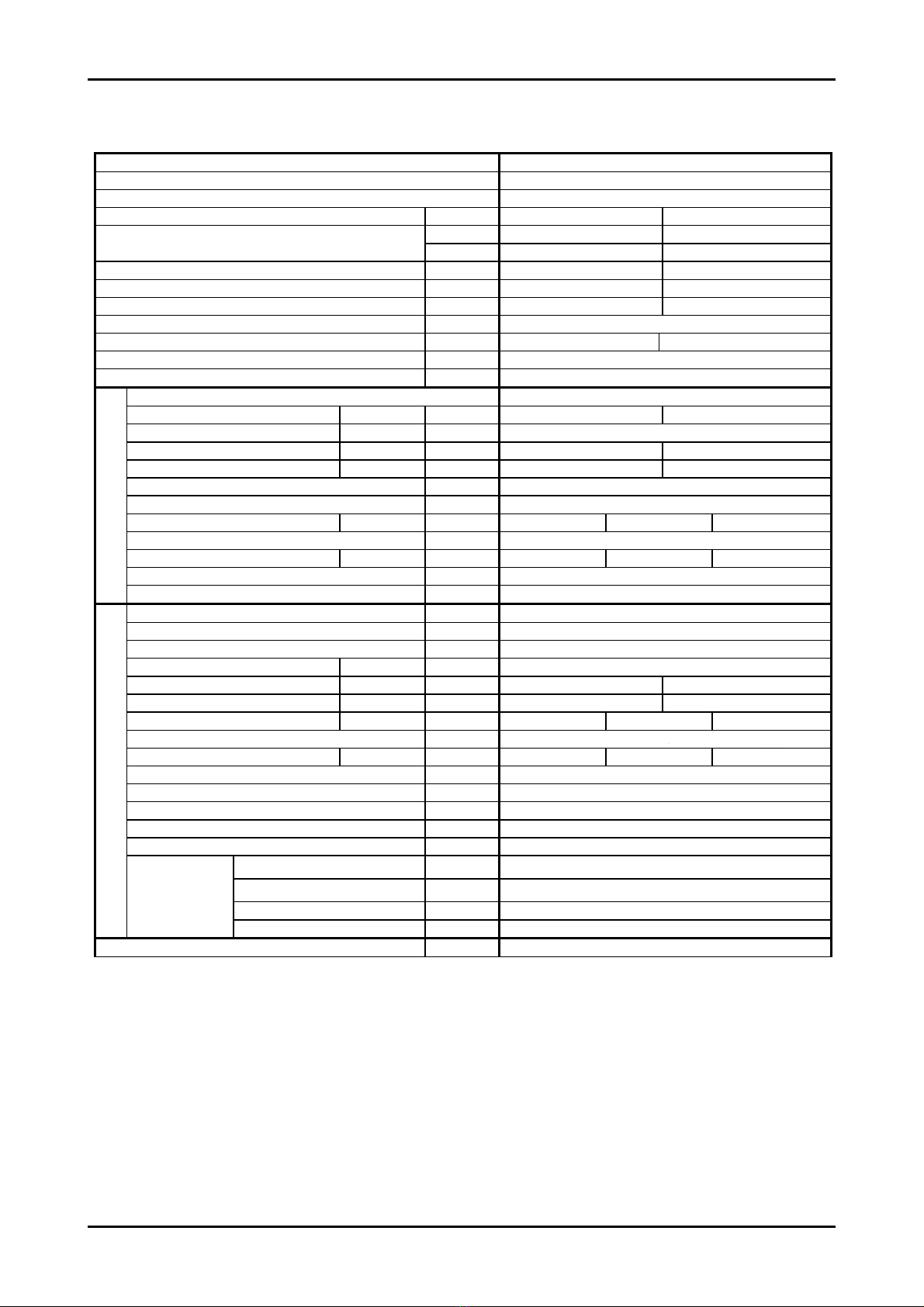
Airwell K DCI Series User manual

Service Manual
K DCI Inverter series
REFRIGERANT
R410A
HEAT PUMP
Indoor Units Outdoor Units
K 9DCI INV GC9 DCI INV
K 12 DCI INV GC12 DCI INV
K 18 DCI INV GC18 DCI INV
TM KDCI-A-1-GB DECEMBER 2004

A
LIST OF EFFECTIVE PAGES
Revision Y05-02 Service Manual − K DCI
LIST OF EFFECTIVE PAGES
Note: Changes in the pages are indicated by a “Revision#” in the footer of each effected page
(when none indicates no changes in the relevant page). All pages in the following list represent
effected/ non effected pages divided by chapters.
Dates of issue for original and changed pages are:
Original ....... 0 ........ December 2004
Total number of pages in this publication is 62 consisting of the following:
Page
No.
Revision
No. #
Page
No.
Revision
No. #
Page
No.
Revision
No. #
Title ....................... 0
A ........................... 0
i............................. 0
1-1 - 1-4 ................ 0
2-1 - 2-4 ................ 0
3-1 - 3-2 ................ 0
4-1 - 4-2 ................ 0
5-1 - 5-12 .............. 0
6-1 - 6-8 ................ 0
7-1 - 7-2 ................ 0
8-1 - 8-2 ................ 1
9-1 - 9-2 ................ 0
10-1-10-2 .............. 0
11-1-11-16............. 2
12-1-12-8 .............. 0
13-1-13-10 ............ 0
Appendix -A ...........0
•Zero in this column indicates an original page.
*Due to constant improvements please note that the data on this service manual can be modified
with out notice.
**Photos are not contractual

i
TABLE OF CONTENTS
Service Manual - K DCI
Table of Contents
1. INTRODUCTION ...................................................................................................1-1
2. PRODUCT DATA SHEET......................................................................................2-1
3. RATING CONDITIONS..........................................................................................3-1
4. OUTLINE DIMENSIONS .......................................................................................4-1
5. PERFORMANCE DATA .......................................................................................5-1
6. PRESSURE CURVES ...........................................................................................6-1
7. ELECTRICAL DATA..............................................................................................7-1
8. WIRING DIAGRAMS .............................................................................................8-1
9. REFRIGERATION DIAGRAMS.............................................................................9-1
10. TUBING CONNECTIONS......................................................................................10-1
11. CONTROL SYSTEM .............................................................................................11-1
12. TROUBLESHOOTING ..........................................................................................12-1

1-1
INTRODUCTION
Service Manual - K DCI
1. INTRODUCTION
1.1 General
The new K DCI INVERTERS split Cassette range comprise the following RC (heat
pump) models:
• K 9DCI INV
• K 12 DCI INV
• K 18 DCI INV
The New DCI K units can be easily fitted to residential and commercial applications
featuring esthetic design, compact dimensions, and low noise operation.
1.2 Main Features
The K DCI INV series benefits from the most advanced innovations, namely:
• DC Inverter technology
• R410A
• High COP (level A)
• Lego Concept
• Pre-Charged units up to the max’ allowing tubing distance
• Networking system connectivity
• Base heater connection
• Cooling operation at outdoor temperature down to -10ºC
• Heating operation at outdoor temperature down to -15ºC
• Bended indoor coil with treated aluminum fins and coating for improved
efficiency.
• Easy access to the interconnecting tubing and wiring connections.
• Automatic treated air sweep.
• Low indoor and outdoor noise levels.
• Easy installation and service.

1-2
INTRODUCTION
Service Manual - K DCI
1.3 Filtration
The KDCI INV series presents several types of air filters:
• Easily accessible, and re-usable pre-filters (mesh)
• Pre-charged electrostatic filter (disposable)
• Active carbon filter (disposable)
1.4 Control
The microprocessor indoor and outdoor controllers, and an infrared remote control,
supplied as standard, provide complete operating function and programming.
Remote controllers: RC-2/3/4/5/7, RCW, µBMS
Networking system AircoNet version 4.2 and up, MIU SW version H8 and up
For further details please refer to the Operation Manual.
1.5 Outdoor Unit
The K DCI INV outdoor units can be installed as floor or wall mounted units by using a
wall supporting bracket. The metal sheets are protected by anti- corrosion paint work
allowing long life resistance. All outdoor units are pre-charged. For further information
please refer to the Product Data Sheet, Chapter 2.
• GC9DCI
• GC12 DCI
• GC18
Outdoor Unit Features:
Features GC9,12, 18, DCI
Display 3 LED’s
Base Heater Optional
Outdoor Fan Variable Speed DC Inverter
M2L cable Port No
1.6 Tubing Connections
Flare type interconnecting tubing to be produced on site.
For further details please refer to the Installation Manual.
1.7 Accessories
• MIU (K) MODBUS Interface Unit
• Base heater
• M2L cable
1.8 Inbox Documentation
Each unit is supplied with its own installation and operation manuals.

1-3
INTRODUCTION
Service Manual - K DCI
1.9 Matching Table
1.9.1 R410A
OUTDOOR UNITS
INDOOR UNITS
MODEL REF. FLO9DCI FLO12 DCI K9 DCI K12 DCI K18 DC
GC9DCI R410A
GC12DCI R410A
GC18DCI R410A
The above table lists outdoor units and K indoor units which can be matched together. In addition
the listed outdoor units can be matched with other types of indoor units such as wall mounted,
.
√
√
√
√
√

2-1
PRODUCT DATA SHEET
Service Manual - K DCI
2. PRODUCT DATA SHEET
2.1 K9DCI
Model Indoor Unit K9DCI
Model Outdoor Unit ONGC9 DCI
Installation Method Flare
Characteristics Units Cooling Heating
Btu/hr 8530 (5120-12970) 11600 (5120-17060)
Capacity(1)
W2500 (1500 - 3800) 3400 (1500 - 5000)
Power Input(1) W
590 (420-1000) 915 (400-1500)
COP(1) W/W
4.24 3.72
Energy Efficiency Class A A
Power Supply V/Ph/Hz 220-240V / 1Ph / 50Hz
Rated Current A 2.7 4.2
Starting Current A 10.50
Circuit Breaker Rating A 16
Fan Type & Quantity Centrifugal*1
Airflow(2) H/M/L m3/hr 570-500-435 600-530-450
External Static Pressure Min-Max Pa N/A
Sound Power Level(3) H/L dB (A)
42-48 42-47
Sound Pressure Level (4) H/L dB (A)
32-38 32-37
Moisture Removal L/hr 1.0
Condensate Drain Tube I.D. mm 16
Dimensions W/H/D mm 571 287 571
Weight kg 22.7
Package Dimensions W/H/D mm 685 415 685
Units per Pallet Units 10
INDOOR
Stacking Height Units 5
Refrigerant Control Electronic Expansion Valve
Compressor Type, Model Single Rotary DC Inverter Panasonic 5RS102XAB
Fan Type & Quantity Axial *1
Airflow H m3/hr 1780
Sound Power Level H dB (A) 60 61
Sound Pressure Level (4) H dB (A) 50 51
Dimensions W/H/D mm 795 610 290
Weight kg 40
Package Dimensions W/H/D mm 945 655 393
Units per Pallet Units 9
Stacking Height Units 3
Refrigerant Type R410A
Refrigerant Chargeless Distance g 1100
Additional Charge Per 1 Meter g/m No Need
Liquid Line (mm)In (6.35) ¼”
Suction Line (mm)In (9.53) ”
Max. Tubing Length m 20
OUTDOOR
Connections
Between Units
Max. Height Difference m 10
Operation Control Type IR Remote Control
(1) Rating conditions in accordance with ISO 5151 and ISO 13253 (for ducted units) and EN14511.
(2) Airflow in ducted units; at nominal external static pressure.
(3) Sound power in ducted units is measured at air discharge.
(4) Sound pressure level measured at 1 meter distance from unit.
38
395

2-2
PRODUCT DATA SHEET
Service Manual - K DCI
2.2 K12 DCI
Model Indoor Unit K12 DCI
Model Outdoor Unit OGC12 DCI
Installation Method Flare
Characteristics Units Cooling Heating
Btu/hr 11940 (5100 - 14960) 14620 (5100 - 18700)
Capacity(1)
W3500 (1500 - 4400) 4300 (1500 - 5500)
Power Input(1) W
950 (420-1250) 1330 (400-1850)
COP(1) W/W
3.68 3.23
Energy Efficiency Class A A
Power Supply V/Ph/Hz 220-240V / 1Ph / 50Hz
Rated Current A 4.1 5.6
Starting Current A 10.50
Circuit Breaker Rating A 16
Fan Type & Quantity Centrifugal*1
Airflow(2) H/M/L m3/hr 580-510-435 620-560-450
External Static Pressure Min-Max Pa N/A
Sound Power Level(3) H/L dB (A)
42-48 42-47
Sound Pressure Level (4) H/L dB (A)
32-38 32-37
Moisture Removal L/hr 1.5
Condensate Drain Tube I.D. mm 16
Dimensions W/H/D mm 571 287 571
Weight kg 24.4
Package Dimensions W/H/D mm 685 415 685
Units per Pallet Units 10
INDOOR
Stacking Height Units 5
Refrigerant Control Electronic Expansion Valve
Compressor Type, Model Single Rotary DC Inverter Panasonic 5RS102XAB
Fan Type & Quantity Axial *1
Airflow H m3/hr 1780
Sound Power Level H dB (A) 62 62
Sound Pressure Level (4) H dB (A)
52 52
Dimensions W/H/D mm 795 610 290
Weight kg 40
Package Dimensions W/H/D mm 945 655 393
Units per Pallet Units 9
Stacking Height Units 3
Refrigerant Type R410A
Refrigerant Chargeless Distance g 1200
Additional Charge Per 1 Meter g/m No Need
Liquid Line (mm)In (6.35) ¼”
Suction Line (mm)In (9.53) ”
Max. Tubing Length m 20
OUTDOOR
Connections
Between Units
Max. Height Difference m 10
Operation Control Type IR Remote Control
(1) Rating conditions in accordance with ISO 5151 and ISO 13253 (for ducted units) and EN14511.
(2) Airflow in ducted units; at nominal external static pressure.
(3) Sound power in ducted units is measured at air discharge.
(4) Sound pressure level measured at 1 meter distance from unit.
38
395

2-4
PRODUCT DATA SHEET
Service Manual - K DCI
2.4 K18 DCI
Model Indoor Unit K18 DCI
Model Outdoor Unit OGC18 DCI
Installation Method Flare
Characteristics Units Cooling Heating
Btu/hr 17060 (4610 – 21840) 21500 (4610 - 25590)
Capacity(1)
W5000 (1350 – 6400) 6300 (1350 – 7500)
Power Input(1) W
1550 (530 – 2000) 1740 (350 – 2080)
COP(1) W/W
3.23 3.62
Energy Efficiency Class A A
Power Supply V/Ph/Hz 220-240V / 1Ph / 50Hz
Rated Current A 7.1 8.0
Starting Current A 10.50
Circuit Breaker Rating A 16
Fan Type & Quantity Centrifugal*1
Airflow(2) H/M/L m3/hr 730-630-510
External Static Pressure Min-Max Pa N/A
Sound Power Level(3) H/M/L dB (A) 46 – 55 - 59
Sound Pressure Level (4) H/M/L dB (A) 36 – 44 - 48.5
Moisture Removal L/hr 2
Condensate Drain Tube I.D. mm 16
Dimensions W/H/D mm 571 287 571
Weight kg 28
Package Dimensions W/H/D mm 685 415 685
Units per Pallet Units 10
INDOOR
Stacking Height Units 5
Refrigerant Control Electronic Expansion Valve
Compressor Type, Model SCROLL Panasonic 5CS130XCC03
Fan Type & Quantity Axial *1
Airflow H m3/hr 2160
Sound Power Level H dB (A) 62 63
Sound Pressure Level (4) H dB (A)
52 53
Dimensions W/H/D mm 795 610 290
Weight kg
43
Package Dimensions W/H/D mm 945 655 393
Units per Pallet Units 9
Stacking Height Units 3
Refrigerant Type R410A
Refrigerant Chargeless Distance g 1500
Additional Charge Per 1 Meter g/m No Need
Liquid Line (mm)In (6.35) ¼”
Suction Line (mm)In (12.7) ½”
Max. Tubing Length m 30
OUTDOOR
Connections
Between Units
Max. Height Difference m 10
Operation Control Type IR Remote Control
(1) Rating conditions in accordance with ISO 5151 and ISO 13253 (for ducted units) and EN14511.
(2) Airflow in ducted units; at nominal external static pressure.
(3) Sound power in ducted units is measured at air discharge.
(4) Sound pressure level measured at 1 meter distance from unit.
395

3-1
RATING CONDITIONS
Service Manual - K DCI
3. RATING CONDITIONS
Standard conditions in accordance with ISO 5151, ISO 13253 (for ducted units)
and EN 14511.
Cooling:
Indoor: 27oC DB 19oC WB
Outdoor: 35 oC DB
Heating:
Indoor: 20oC DB
Outdoor: 7oC DB 6oC WB
3.1 Operating Limits
Indoor Outdoor
Cooling Upper limit 32oC DB 23oC WB 46oC DB
Lower limit 21oC DB 15oC WB -10oC DB
Heating Upper limit 27oC DB 24oC DB 18oC WB
Lower limit 10oC DB -15oC DB -16oC WB
Voltage 1PH 198 – 264 V
3PH N/A

4-1
OUTLINE DIMENSIONS
Service Manual - K DCI
4. OUTLINE DIMENSIONS
4.1 Indoor Unit: K 9, 12, 18 DCI
4.2 Outdoor Unit: GC9, 12, 18 DCI

5-1
PERFORMANCE DATA
Service Manual - K DCI
5. PERFORMANCE DATA
5.1 K9DCI
5.1.1 Cooling Capacity (kW) - Run Mode
ID COIL ENTERING AIR DB/WB TEMPERATURE [ºC]
OD COIL
ENTERING AIR DB
TEMPERATURE [C0]
DATA 22/15 24/17 27/19 29/21 32/23
-10 - 20
(protection range)
TC 80 - 110 % of nominal
SC 80 - 105 % of nominal
PI 25 - 50 % of nominal
25
TC 2.42 2.57 2.73 2.89 3.05
SC 2.09 2.13 2.18 2.22 2.26
PI 0.46 0.47 0.48 0.49 0.50
30
TC 2.30 2.46 2.62 2.77 2.93
SC 2.04 2.08 2.12 2.17 2.21
PI 0.52 0.53 0.54 0.54 0.55
35
TC 2.18 2.34 2.50 2.66 2.82
SC 1.98 2.03 2.07 2.11 2.16
PI 0.57 0.58 0.59 0.60 0.61
40
TC 2.07 2.23 2.38 2.54 2.70
SC 1.93 1.97 2.02 2.06 2.10
PI 0.63 0.64 0.64 0.65 0.66
46
TC 1.93 2.09 2.24 2.40 2.56
SC 1.87 1.91 1.95 2.00 2.04
PI 0.69 0.70 0.71 0.72 0.73
LEGEND
TC – Total Cooling Capacity, kW
SC – Sensible Capacity, kW
PI – Power Input, kW
WB – Wet Bulb Temp., (oC)
DB – Dry Bulb Temp., (oC)
ID – Indoor
OD – Outdoor
5.1.2 Capacity Correction Factors
Cooling Capacity Ratio Vs. Outdoor Temperature
0.5
0.6
0.7
0.8
0.9
1
1.1
1.2
20 25 30 35 40 45
Outdoor Temperature [deg C]
Capacity Ration

5-2
PERFORMANCE DATA
Service Manual - K DCI
5.1.3 Heating Capacity (kW) - Run Mode
ID COIL ENTERING AIR DB TEMPERATURE [ºC]
OD COIL
ENTERING AIR DB/
WB TEMPERATURE
[ºC]
DATA 15 20 25
-15/-16 TC 2.16 2.01 1.86
PI 0.55 0.60 0.66
-10/-12 TC 2.41 2.26 2.11
PI 0.66 0.72 0.77
-7/-8 TC 2.59 2.44 2.29
PI 0.75 0.80 0.86
-1/-2 TC 2.68 2.53 2.38
PI 0.79 0.84 0.90
2/1 TC 2.75 2.59 2.44
PI 0.82 0.87 0.93
7/6 TC 3.55 3.40 3.25
PI 0.86 0.92 0.97
10/9 TC 3.75 3.60 3.44
PI 0.91 0.97 1.02
15/12 TC 3.94 3.79 3.64
PI 0.96 1.02 1.07
15-24 TC 85 - 105 % of nominal
(Protection Range) PI 80 - 120 % of nominal
LEGEND
TC – Total Cooling Capacity, kW
PI – Power Input, kW
WB – Wet Bulb Temp., (oC)
DB – Dry Bulb Temp., (oC)
ID – Indoor
OD – Outdoor
5.1.4 Capacity Correction Factors
Heating Capacity Ratio Vs. Outdoor Temperature
0.5
0.6
0.7
0.8
0.9
1
1.1
1.2
-15 -10 -5 0 5 10 15
Outdoor WB Temperature [deg C]
Capacity Ration

5-3
PERFORMANCE DATA
Service Manual - K DCI
5.2 Capacity Correction Factor Due to Tubing Length
5.2.1 Cooling
0.91
0.92
0.93
0.94
0.95
0.96
0.97
0.98
0.99
1.00
1.01
3 4 5 6 7 8 9 1011121314151617181920
Tubing Length [m]
Capacity Ratio
5.2.2 Heating
0.90
0.92
0.94
0.96
0.98
1.00
1.02
3 4 5 6 7 8 9 10 11 12 13 14 15 16 17 18 19 20
Tubing Length [m]
Capacity Ratio

5-4
PERFORMANCE DATA
Service Manual - K DCI
5.3 K12 DCI
5.3.1 Cooling Capacity (kW) - Run Mode
ID COIL ENTERING AIR DB/WB TEMPERATURE [ºC]
OD COIL
ENTERING AIR DB
TEMPERATURE [ºC]
DATA 22/15 24/17 27/19 29/21 32/23
-10 - 20
(protection range)
TC 80 - 110 % of nominal
SC 80 - 105 % of nominal
PI 25 - 50 % of nominal
25
TC 3.38 3.60 3.83 4.05 4.27
SC 2.65 2.70 2.75 2.81 2.86
PI 0.75 0.76 0.78 0.79 0.80
30
TC 3.22 3.44 3.66 3.88 4.11
SC 2.58 2.63 2.69 2.74 2.79
PI 0.83 0.85 0.86 0.88 0.89
35
TC 3.06 3.28 3.50 3.72 3.94
SC 2.51 2.57 2.62 2.67 2.73
PI 0.92 0.94 0.95 0.96 0.98
40
TC 2.89 3.12 3.34 3.56 3.78
SC 2.45 2.50 2.55 2.61 2.66
PI 1.01 1.02 1.04 1.05 1.07
46
TC 2.70 2.92 3.14 3.36 3.58
SC 2.37 2.42 2.47 2.53 2.58
PI 1.11 1.13 1.14 1.16 1.17
LEGEND
TC – Total Cooling Capacity, kW
SC – Sensible Capacity, kW
PI – Power Input, kW
WB – Wet Bulb Temp., (oC)
DB – Dry Bulb Temp., (oC)
ID – Indoor
5.3.2 Capacity Correction Factors
Cooling Capacity Ratio Vs. Outdoor Temperature
0.5
0.6
0.7
0.8
0.9
1
1.1
1.2
20 25 30 35 40 45
Outdoor Temperature [deg C]
Capacity Ration

5-5
PERFORMANCE DATA
Service Manual - K DCI
5.3.3 Heating Capacity (kW) - Run Mode
ID COIL ENTERING AIR DB TEMPERATURE [ºC]
OD COIL
ENTERING AIR DB/
WB TEMPERATURE
[ºC]
DATA 15 20 25
-15/-16 TC 2.74 2.55 2.35
PI 0.80 0.88 0.96
-10/-12 TC 3.05 2.86 2.66
PI 0.96 1.04 1.12
-7/-8 TC 3.28 3.09 2.90
PI 1.09 1.17 1.25
-1/-2 TC 3.39 3.20 3.01
PI 1.15 1.23 1.31
2/1 TC 3.47 3.28 3.09
PI 1.19 1.27 1.35
7/6 TC 4.49 4.30 4.11
PI 1.25 1.33 1.41
10/9 TC 4.74 4.55 4.36
PI 1.32 1.40 1.49
15/12 TC 4.99 4.80 4.60
PI 1.40 1.48 1.56
15-24 TC 85 - 105 % of nominal
(Protection Range) PI 80 - 120 % of nominal
LEGEND
TC – Total Cooling Capacity, kW
PI – Power Input, kW
WB – Wet Bulb Temp., (oC)
DB – Dry Bulb Temp., (oC)
ID – Indoor
OD – Outdoor
5.3.4 Capacity Correction Factors
Heating Capacity Ratio Vs. Outdoor Temperature
0.5
0.6
0.7
0.8
0.9
1
1.1
1.2
-15 -10 -5 0 5 10 15
Outdoor WB Temperature [deg C]
Capacity Ration

5-6
PERFORMANCE DATA
Service Manual - K DCI
5.4 Capacity Correction Factor Due to Tubing Length
5.4.1 Cooling
0.91
0.92
0.93
0.94
0.95
0.96
0.97
0.98
0.99
1.00
1.01
3 4 5 6 7 8 9 1011121314151617181920
Tubing Length [m]
Capacity Ratio
5.4.2 Heating
0.90
0.92
0.94
0.96
0.98
1.00
1.02
3 4 5 6 7 8 9 1011121314151617181920
Tubing Length [m]
Capacity Ratio

5-10
PERFORMANCE DATA
Service Manual - K DCI
5.7 K18 DCI
5.7.1 Cooling Capacity (kW) - Run Mode
ID COIL ENTERING AIR DB/WB TEMPERATURE [ºC]
OD COIL
ENTERING AIR DB
TEMPERATURE [ºC]
DATA 22/15 24/17 27/19 29/21 32/23
-10 - 20
(protection range)
TC 80 - 110 % of nominal
SC 80 - 105 % of nominal
PI 25 - 50 % of nominal
25
TC 4.85 5.13 5.42 5.70 5.99
SC 3.30 3.35 3.40 3.45 3.50
PI 1.20 1.23 1.26 1.28 1.31
30
TC 4.60 4.88 5.17 5.45 5.74
SC 3.17 3.22 3.27 3.32 3.37
PI 1.37 1.40 1.42 1.45 1.48
35
TC 4.35 4.63 4.92 5.20 5.49
SC 3.04 3.09 3.14 3.19 3.24
PI 1.54 1.56 1.59 1.62 1.64
40
TC 4.10 4.39 4.67 4.96 5.24
SC 2.91 2.96 3.01 3.06 3.11
PI 1.70 1.73 1.76 1.78 1.81
46
TC 3.80 4.09 4.37 4.66 4.94
SC 2.76 2.81 2.86 2.91 2.95
PI 1.90 1.93 1.96 1.98 2.01
LEGEND
TC – Total Cooling Capacity, kW
SC – Sensible Capacity, kW
PI – Power Input, kW
WB – Wet Bulb Temp., (oC)
DB – Dry Bulb Temp., (oC)
ID – Indoor
OD – Outdoor
5.7.2 Capacity Correction Factors
Cooling Capacity Ratio Vs. Outdoor Temperature
0.5
0.6
0.7
0.8
0.9
1
1.1
1.2
20 25 30 35 40 45
Outdoor Temperature [deg C]
Capacity Ration

5-11
PERFORMANCE DATA
Service Manual - K DCI
5.7.3 Heating Capacity (kW) - Run Mode
ID COIL ENTERING AIR DB TEMPERATURE [ºC]
OD COIL ENTERING
AIR DB/WB
TEMPERATURE [ºC]
DATA 15 20 25
-15/-16 TC 2.66 2.28 1.90
PI 1.15 1.23 1.31
-10/-12 TC 3.52 3.13 2.75
PI 1.30 1.38 1.46
-7/-8 TC 4.16 3.77 3.39
PI 1.41 1.49 1.57
-1/-2 TC 4.47 4.09 3.71
PI 1.46 1.55 1.63
2/1 TC 4.69 4.30 3.92
PI 1.50 1.58 1.66
7/6 TC 6.24 5.85 5.47
PI 1.56 1.64 1.72
10/9 TC 6.56 6.18 5.79
PI 1.59 1.67 1.75
15/12 TC 6.88 6.50 6.12
PI 1.62 1.70 1.78
15-24
(Protection Range)
TC 85 - 105 % of nominal
PI 80 - 120 % of nominal
LEGEND
TC – Total Cooling Capacity, kW
PI – Power Input, kW
WB – Wet Bulb Temp., (oC)
DB – Dry Bulb Temp., (oC)
ID – Indoor
OD – Outdoor
5.7.4 Capacity Correction Factors
Heating Capacity Ratio Vs. Outdoor Temperature
0.4
0.5
0.6
0.7
0.8
0.9
1
1.1
1.2
-15 -10 -5 0 5 10 15
Outdoor WB Temperature [deg C]
Capacity Ration

5-12
PERFORMANCE DATA
Service Manual - K DCI
5.8 Capacity Correction Factor Due to Tubing Length
5.8.1 Cooling
0.993
0.994
0.995
0.996
0.997
0.998
0.999
1.000
1.001
0 5 10 15 20 25 30 35
Tubing Length[m]
Capacity Ratio
5.8.2 Heating
0.86
0.88
0.90
0.92
0.94
0.96
0.98
1.00
1.02
0 5 10 15 20 25 30 35
Tubing Length[m]
Capacity Ratio
This manual suits for next models
6
Table of contents
Other Airwell Inverter manuals
Popular Inverter manuals by other brands

ABB
ABB PVI-3.0-OUTD-US Quick installation guide

Victron energy
Victron energy MultiPlus 12/500/20 manual

Riello
Riello HELIOTERM Design Inverter 11B Instructions for the installer and the technical service centre

Studer
Studer next 3 quick guide

Plasmatronics
Plasmatronics D2020N user guide

Build Worker
Build Worker BGD2001IS owner's manual

Siemens
Siemens SINAMICS V20 Inverter operating instructions

YSmart Technology
YSmart Technology IP Series Grid Tie inverter user manual

LIGHTBOX
LIGHTBOX LIGHTBOX POWERPACK user manual

Porto
Porto HT-E-100-12 user guide

Dometic
Dometic TEC Series operating manual

ABB
ABB UNO-DM-6.0-TL-PLUS Quick installation guide