Peak Scientific NG2000A User manual
NG3000-5000 User Manual Rev 2 RSID 197 06/10/21
NG3000(A) & 5000(A)
User Manual

Contents
Change History 3
How to use this Manual 3
Introduction 4
Warranties and Liabilities 5
Safety Notices 6
Symbols 6
Safety Notice to Users 6
Declaration of Conformity 7
Environmental Declaration 8
Technical Specification 9
Unpacking 13
Installation 14
Generator Environment 14
Removing the generator from the shipping crate 15
Generator Overview 16
General Dimensions 16
Removal of Transit Brackets 17
Wall Mounting 18
Rear Connections 19
Electrical Connection 20
Fuse 20
Start-Up Sequence 21
Normal Operation 22
Unusual Operation 22
Service Requirements 23
Service Schedule 23
Peak Protected 24
Cleaning 25
Page 2

Page 3
Change History
Rev Comment Name Date
How to use this Manual
This manual is intended for end users and has been written as a reference document
where you can skip to the relevant information.
Users can refer to the contents page to find the relevant information.
Please review each of the following sections carefully.
Thank you for selecting Peak Scientific to meet your gas generation needs, and should
you require any further assistance or support please do not hesitate to contact Peak
Scientific or the Peak Partner from which you purchased your generator.
REV 2 Declaration update D.Lai 12/10/2021

Page 4
Introduction
The NG range of ultra high purity nitrogen generators have been designed primarily
for GC applications and other applications requiring the highest purity nitrogen.
These models provide a source of Nitrogen gas with other features including:
• Available with or without an external compressor
• Contains self-regenerating Carbon Molecular Sieve purification
• The most convenient method of laboratory gas supply
• Gas is supplied on demand so generator works to your schedule
• Remove the hassle and safety concerns with ordering and replacing pressurized
cylinder gas
• 12 month comprehensive on-site warranty
Delivering flow rates of 3000cc/min or 5000cc/min, these generators come in
two variants, the standard model and the enhanced (A) models which feature an
integrated compressor, removing the need for an external air supply to be present in
the lab.
To reach their ultra high purity nitrogen output these generators use Pressure Swing
Adsorption and Carbon Molecular Sieve. These separation technologies remove
oxygen and other impurities in air, delivering hassle-free, ultra high purity nitrogen,
on-demand for the lab.

Page 5
Warranties and Liabilities
1. The Company warrants that it has title to the Goods.
2. Subject to the provisions of this clause the Company warrants that the Goods
shall comply in all material respects with any specification referred to in the Order
Confirmation (as the same may be amended) and shall, subject thereto, be free
from defects in material and workmanship for the lesser of a period of twelve
months from the date of delivery or thirteen months from the date of dispatch
from the factory.
3. Save as provided in this clause and except where the Goods are sold to a person
dealing as a consumer (within the meaning of the Unfair Contract Terms Act
1977) all warranties, conditions or other terms implied by statute or common
law are hereby expressly excluded save to the extent they may not be lawfully
excluded. When the Goods are sold to a consumer within the meaning of the Unfair
Contract Terms Act 1977 their statutory rights are not aected by the provisions of
this clause.
4. In the event of the Customer making a claim in respect of any defect in terms of
clause 2 hereof the Customer must.
1. Reasonably satisfy the Company that the Goods have been properly installed,
commissioned, stored, serviced and used and without prejudice to the generality
of the foregoing that any defect is not the direct or indirect result of lack of repair
and/or servicing, incorrect repair and/or servicing, use of wrong materials and/or
incorrect spare parts
2. Allow the company to inspect the Goods and/or any installation and any
relevant packaging as and when reasonably required by the Company.
5. Subject to the Company being notified of any defect as is referred to in sub-
clause 2 hereof within a reasonable time of it becoming apparent and subject
always to the terms of sub-clause 4 hereof, the Company shall, in its option, replace
or repair the defective Goods or refund a proportionate part of the Price. The
Company shall have no further liability to the Customer (save as mentioned in sub-
clause 6 hereof).
6. The Company shall be liable to indemnify the Customer in respect of any claim
for death or personal injury to any person in so far as such is attributable to the
negligence or breach of duty of the Company or any failure by the Company to
comply with the provisions of sub-clause 2 hereof.
7. Save as provided in sub-clause 2 hereof the Company shall not be liable in respect
of any claim by the Customer for costs, damages, loss or expenses (whether direct,
indirect, consequential or otherwise) or indemnity in any respect howsoever arising
including, but not by way of limitation, liability arising in negligence (other than
pursuant to clause 6 above) that may be suered by the Customer or any third
party.
WARNING
WARNING
WARNING
WARNING
CAUTION
Page 6
Safety Notices
Peak Scientific Instruments cannot anticipate every possible circumstance which
may represent a potential hazard. The warnings detailed within this manual refer to
the most likely potential hazards, but by definition cannot be all inclusive. If the user
employs an operating procedure, item of equipment or a method of working which
is not specifically recommended by Peak Scientific, the user must ensure that the
equipment will not be damaged or become hazardous to persons or property.
Symbols
This manual uses the following symbols to highlight specific areas important to the
safe and proper use of the generator.
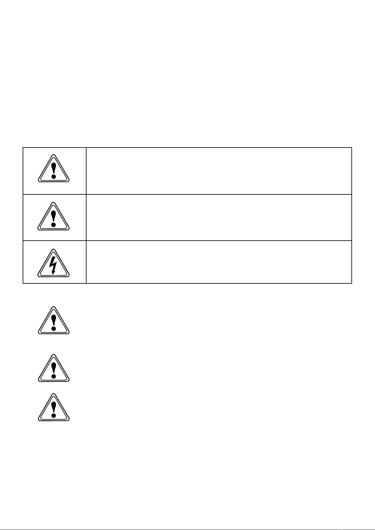
A WARNING notice denotes a hazard. It calls attention to an operating procedure,
process or similar, which if not correctly performed or adhered to, could cause
personal injury or in the worst case death. Do not proceed beyond a WARNING
notice until the indicated conditions are fully understood or met.
A CAUTION notice denotes a hazard. It calls attention to an operating procedure,
process or similar, which if not correctly performed or adhered to, could cause
damage to the generator or the application. Do not proceed beyond a CAUTION
notice until the indicated conditions are fully understood or met.
Caution, risk of electric shock. Ensure power to the generator has been removed
before proceeding.
Safety Notice to Users
These instructions must be read thoroughly and understood before
installation and operation of your Peak Generator. Use of the
generator in a manner not specified by Peak Scientific MAY impair the
SAFETY provided by the equipment.
When handling, operating or carrying out any maintenance, personnel
must employ safe engineering practices and observe all relevant local
health and safety requirements and regulations. The attention of UK
users is drawn to the Health and Safety at Work Act 1974, and the
Institute of Electrical Engineers regulations.
If the equipment is used in a manner not specified by the
manufacturer, the protection provided by the equipment maybe
impaired.
No. 2 EU DOC

No. 2 EU DOC
EU Declaration of Conformity
We Peak Scientific Instruments Ltd.
Of Fountain Crescent, Inchinnan, Renfrewshire, PA4 9RE
Hereby declare that, this declaration of conformity is issued under the sole
responsibility of the manufacturer.
Equipment: Nitrogen Generator
Models: NG*000(A) Series
* Denotes any numeric value.
(A) Denotes compressor based model.
To which this declaration relates, is in conformity with the following applicable EU
Directives, harmonized standards, and other normative requirements.
• Low Voltage Directive 2014/35/EU
EN 61010-1: 2010 Safety Requirements for Electrical Equipment for Measurement,
Control and Laboratory Use.
• Electromagnetic Compatibility Directive 2014/30/EU
EN 61326-1: 2013 Electrical Equipment for Measurement, Control and Laboratory
Use – EMC Requirements. (Class A)
• Restriction on the use of certain hazardous substances in electronic equipment
(RoHS) Directive 2011/65/EU as amended by EU 2015/863.
• FCC 47 CFR Part 15 class A
Unintentional radiators; Conducted and Radiated emissions limits.
Signed for and on behalf of Peak Scientific by
Signed:
Name: Fraser Dunn
Position: Design Engineering Manager
Peak Scientific Instruments ltd,
Inchinnan, Renfrew, Scotland, PA4 9RE, UK.
Date: 10th August 2021

No. 6 EU PED DOC
UK Declaration of Conformity
We Peak Scientific Instruments Ltd.
Of Fountain Crescent, Inchinnan, Renfrewshire, PA4 9RE
Hereby declare that, this declaration of conformity is issued under the sole
responsibility of the manufacturer.
Equipment: Nitrogen Generator
Models: NG*000(A) Series
* Denotes any numeric value.
(A) Denotes compressor based model.
To which this declaration relates, is in conformity with the following applicable UK
Statutory Instruments, Standards and other normative requirements.
• The Electrical Equipment (Safety) Regulations 2016 (SI 2016 / 1101) as amended.
BS61010-1:2010 Safety Requirements for Electrical Equipment for Measurement
Control and Laboratory Use.
• The Electromagnetic Compatibility Regulations 2016 (SI 2016 / 1091) as amended.
BS61326-1:2013 Electrical Equipment for Measurement , Control and Laboratory Use
– EMC Requirements.
• The Restriction of the Use of Certain Hazardous Substances in Electrical and
Electronic Equipment Regulations 2012 (SI 2012 / 3032) as amended.
Signed for and on behalf of Peak Scientific by
Signed:
Name: Fraser Dunn
Position: Design Engineering Manager
Peak Scientific Instruments ltd,
Inchinnan, Renfrew, Scotland, PA4 9RE, UK.
Date: 10th August 2021
No. 3 UK DOC

No. 6 EU PED DOC
WEEE Compliance Statement
The Waste Electrical and Electronic Equipment (WEEE) Regulations SI 2013 No 3113
and or the Waste Electrical and Electronic Equipment (WEEE) Directive 2012/19/EU
apply to all electrical and electronic equipment placed on the market in the UK and EU
covered by the scope of regulations which can be found in the Government Guidance
Notes (PDF) produced by the Department for Business Innovation and skills for the UK
and here for Europe.
All PEAK products that are subject to the WEEE directive are compliant with the
WEEE marking requirement. Such products are marked with the “crossed-out wheelie
bin” symbol (shown below) in accordance with European standard EN50419. All
old electrical equipment can be recycled. Please do not dispose of any electrical
equipment (including those marked with this symbol) in general rubbish bins. Please
contact your dealer or distributor for clarity.
No. 3 UK DOC

Page 10
Technical Specification
NG3000
Environment
Minimum Operating Ambient Temperature 5°C (41°F)
Maximum Operating Ambient Temperature 25°C (75°F)
Maximum Altitude 2000 m
Maximum Relative Humidity 80% Non-Condensing
Minimum Storage Temperature* 10°C (50°F)
Maximum Storage Temperature* 25°C (75°F)
*NOTE – When taken out of storage the Generator should be allowed to acclimatize at room temperature
for a minimum of 3 hours before operation.
Inlet Conditions
Minimum Air Pressure 8.2 bar (120 psi)
Maximum Air Pressure 8.8 bar (130 psi)
Generator Outlets
Maximum Gas Output Pressure 5.5 bar (80 psi)
Maximum Outlet Flow Rate 3000 cc/min (0.10 cfm)
Particles <0.01µm
Phthalates NONE
Suspended Liquids NONE
Gas Outlets 1 x ¼” BSPP
Start-Up Time For Purity 8 hours
Electrical Requirements
Voltage 230v or 110v
Frequency 50/60 Hz
Current 0.5 (1.2) A
Pollution Degree 2
Insulation Category II
General
Dimensions cm (inches) WxDxH 43 (16.9) x 41 (16.1) x 1235 (48.6)
Generator Weight Kg (lbs) 77 (170)
Shipping Weight Kg (lbs) 107 (236)

Page 11
Technical Specification
NG3000A
Environment
Minimum Operating Ambient Temperature 5°C (41°F)
Maximum Operating Ambient Temperature 35°C (95°F)
Maximum Altitude 2000 m
Maximum Relative Humidity 80% Non-Condensing
Minimum Storage Temperature* 10°C (50°F)
Maximum Storage Temperature* 25°C (75°F)
*NOTE – When taken out of storage the Generator should be allowed to acclimatize at room temperature
for a minimum of 3 hours before operation.
Generator Outlets
Maximum Gas Output Pressure 5.5 bar (80 psi)
Maximum Outlet Flow Rate 3000 cc/min (0.10 cfm)
Particles <0.01µm
Phthalates NONE
Suspended Liquids NONE
Gas Outlets 1 x ¼” BSPP
Start-Up Time For Purity 8 hours
Electrical Requirements
Voltage 230v or 110v
Frequency 50/60 Hz
Current 3.6 (8) A
Pollution Degree 2
Insulation Category II
General
Dimensions cm (inches) WxDxH 43 (16.9) x 41 (16.1) x 1235 (48.6)
Generator Weight Kg (lbs) 88 (194)
Shipping Weight Kg (lbs) 128 (282)
Page 12
Technical Specification
NG5000
Environment
Minimum Operating Ambient Temperature 5°C (41°F)
Maximum Operating Ambient Temperature 25°C (75°F)
Maximum Altitude 2000 m
Maximum Relative Humidity 80% Non-Condensing
Minimum Storage Temperature* 10°C (50°F)
Maximum Storage Temperature* 25°C (75°F)
*NOTE – When taken out of storage the Generator should be allowed to acclimatize at room temperature
for a minimum of 3 hours before operation.
Inlet Conditions
Minimum Air Pressure 8.2 bar (120 psi)
Maximum Air Pressure 8.8 bar (130 psi)
Generator Outlets
Maximum Gas Output Pressure 5.5 bar (80 psi)
Maximum Outlet Flow Rate 5000 cc/min (0.17 cfm)
Particles <0.01µm
Phthalates NONE
Suspended Liquids NONE
Gas Outlets 1 x ¼” BSPP
Start-Up Time For Purity 8 hours
Electrical Requirements
Voltage 230v or 110v
Frequency 50/60 Hz
Current 0.5 (1.2) A
Pollution Degree 2
Insulation Category II
General
Dimensions cm (inches) WxDxH 43 (16.9) x 41 (16.1) x 1235 (48.6)
Generator Weight Kg (lbs) 77 (170)
Shipping Weight Kg (lbs) 107 (236)

Page 13
Technical Specification
NG5000A
Environment
Minimum Operating Ambient Temperature 5°C (41°F)
Maximum Operating Ambient Temperature 35°C (95°F)
Maximum Altitude 2000 m
Maximum Relative Humidity 80% Non-Condensing
Minimum Storage Temperature* 10°C (50°F)
Maximum Storage Temperature* 25°C (75°F)
*NOTE – When taken out of storage the Generator should be allowed to acclimatize at room temperature
for a minimum of 3 hours before operation.
Generator Outlets
Maximum Gas Output Pressure 5.5 bar (80 psi)
Maximum Outlet Flow Rate 5000 cc/min (0.17 cfm)
Particles <0.01µm
Phthalates NONE
Suspended Liquids NONE
Gas Outlets 1 x ¼” BSPP
Start-Up Time For Purity 8 hours
Electrical Requirements
Voltage 230v or 110v
Frequency 50/60 Hz
Current 3.6 (8) A
Pollution Degree 2
Insulation Category II
General
Dimensions cm (inches) WxDxH 43 (16.9) x 41 (16.1) x 1235 (48.6)
Generator Weight Kg (lbs) 88 (194)
Shipping Weight Kg (lbs) 128 (282)

Page 14
Unpacking
Although Peak Scientific takes every precaution with safe transit and packaging, it is
advisable to fully inspect the unit for any sign of transit damage.
Check ‘SHOCKWATCH’ and ‘TIP-N-TELL’ labels for signs of rough handling prior to
unpacking.
Any damage should be reported immediately to the carrier and Peak Scientific or the
Peak Partner from where the unit was purchased.
Follow the unpacking instructions posted on the side of the crate. It will require two
people to remove the unit from the shipping crate and to manoeuvre the generator to
the desired location.
Please save the product packaging for storage or future shipment of the generator.
Note: Included with the generator is a “Fittings Kit” containing mains power leads
for UK, EU & US and also all the required fittings and warranty registration card. Be
careful not to discard these with the packaging.
Page 14

Page 15
Installation
Generator Environment
The generator is designed for indoor use only. It should be installed adjacent to
the application(s) it is supplying. If this is not convenient then the unit can be sited
elsewhere, however, consideration should be made of the lengths of pipe runs as
pressure drops can result from extended runs of pipe.
Performance of the generator (like all sophisticated equipment) is aected by
ambient conditions. Note should also be taken to the proximity of Air Conditioning
outlets. These can sometimes give rise to “pockets” of air with high relative humidity.
Operation of the unit within such a pocket could adversely aect its performance.
Consideration should also be given to the air flow around the unit. It is recommended
that an air gap of 75mm (3”) should be maintained down both sides and at the rear of
the unit. Please refer to the drawing below for the general dimensions of the unit.
Minimum Operating Ambient Temperature: 5 °C (41 °F)
Maximum Operating Ambient Temperature: 35 °C (95 °F)

Page 16
Removing the generator from the shipping crate
The generator weighs over 57kg and as such should be unpacked by two people using
the following method.
All the screws encircled in RED should first be removed from the shipping crate, there
are approximately 16 screws, and the front door should then be removed.
Now, with someone positioned at either side of the shipping crate, the top half of the
crate can be slid backwards and away from the rest of the crate. With the top of the
crate removed the foam insert of top of the generator should also be taken o.
The generator can now be lifted out of the crate base and onto the floor. This should
be done again with someone positioned at either side. There is a gap in the foam base
for hand access, one hand should be positioned here underneath the generator and
the other at the back supporting the weight. The generator should then be tilted back
slightly and then up and out of the foam base and onto the floor.

Page 17
Generator Overview
General Dimensions
The generator must always be placed on a flat, level surface. Failure to
do so will aect the performance of the generator.
WARNING
430.00 mm
410.00 mm
1235.00 mm

Page 18
Removal of Transit Brackets
The transit brackets must be removed prior to switching the unit on.
Failure to do so will result in damage to the equipment. This will void
the warranty on the Generator and will result in a chargeable repair.
To remove the transit bracket first remove the 11 screws on the front panel as shown,
then remove the front panel from the generator.
Now locate the red transit bracket attached to the compressor foot plate, and remove
the two screws on the bracket. Next remove the transit bracket by first lifting up and
then out of the generator.
Replace the front panel and secure it to the generator using the 11 screws that were
previously removed.
CAUTION
Page 19
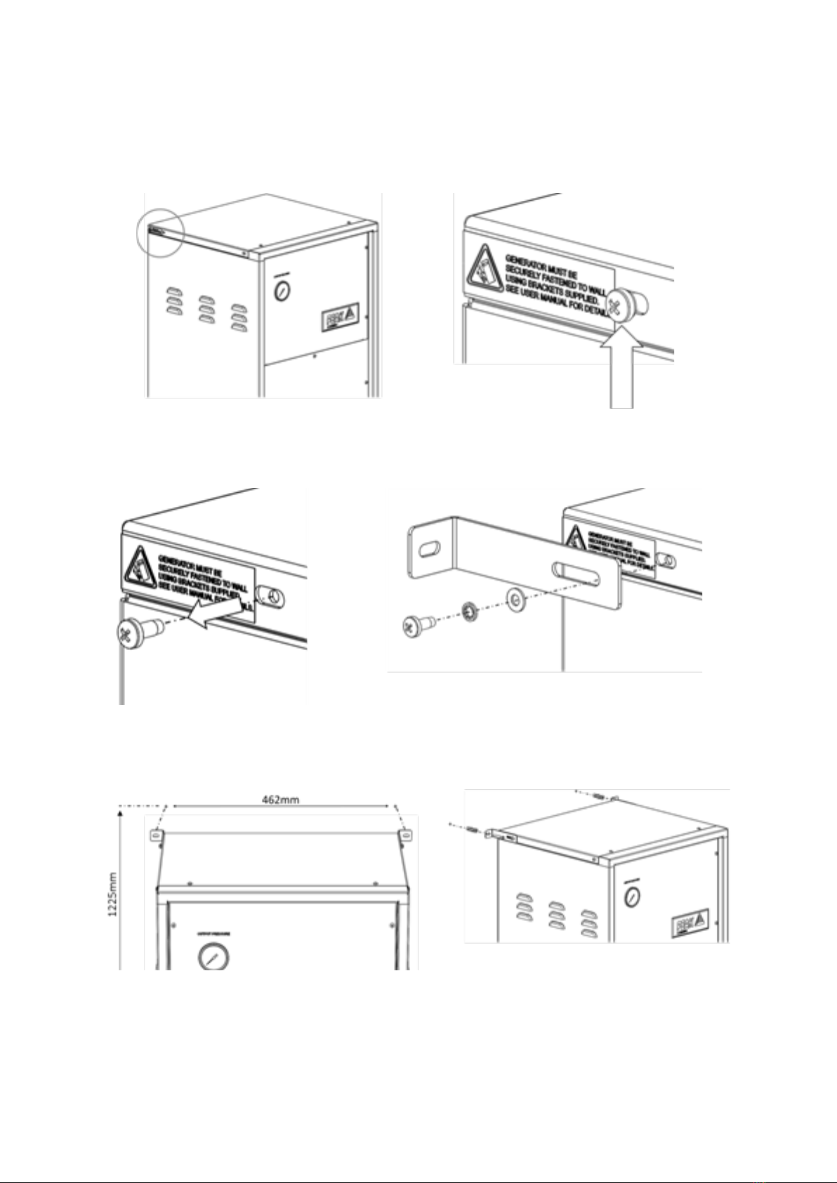
Wall Mounting
The NG range generator is designed to be mounted against a wall for safety reasons.
Supplied in the generator fittings kit are all the fittings required to wall mount the
generator. Detailed below are the necessary steps to mount the unit to a wall.
Locate the screw in the top rear corner of the unit, beside the yellow warning label.
Remove the screw from the generator this should be repeated for the other side of the
unit, and retain.
Next, using the screw which was removed, fit the bracket and washers provided to the
generator. Again this should be repeated for the other side. The bracket is adjustable
to accommodate varying kickboard widths.
Finally, using the dimensions provided, fix the wall plugs to the wall, ensuring wall
plug is suitable for the type of wall. If not, use the correct type. Secure the generator
to the wall with the screws from the fittings kit.
Page 20
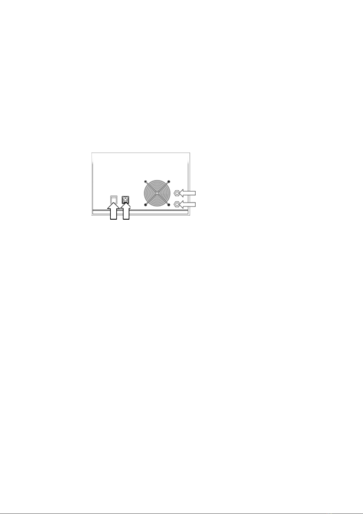
Rear Connections
The Nitrogen Generator should be connected to a clean, dry source of compressed
air. A minimum pressure of 120 psi is required. Any doubts as to the suitability of the
compressed air supply should be referred to the factory for advice.
The generator has two ¼” BSPT bulkhead connections to the left side of the unit.
The upper port is the Compressed Air inlet and the lower is the Nitrogen outlet. A
¹/8” Swagelok fitting is supplied for connection to the application. There is no drain
on this machine. Any moisture liberated by the filter separator is discharged through
the high capacity exhaust system, where sudden reduction in pressure causes instant
evaporation. The water vapour is safely removed from the unit by the ventilation
system.
Air Inlet
Nitrogen Outlet
Power Switch Power Inlet/Fuse Drawer
This manual suits for next models
4
Table of contents
Other Peak Scientific Inverter manuals


