INTRODUCTION
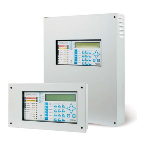
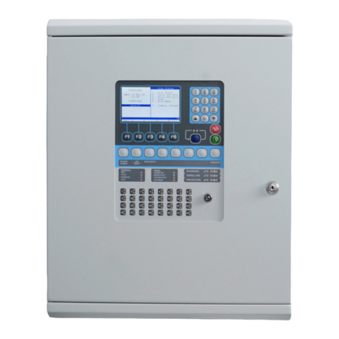
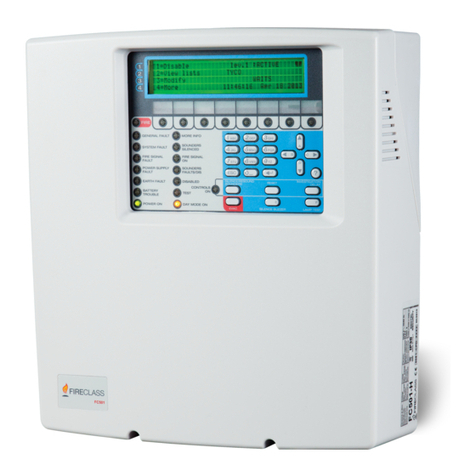
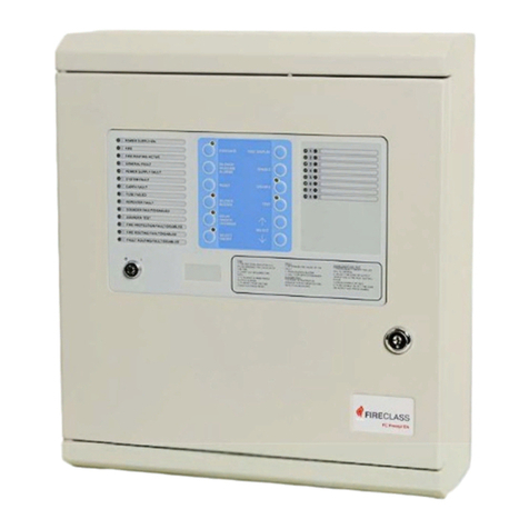
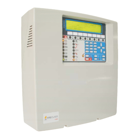
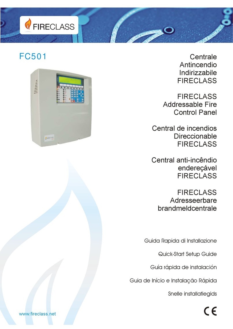
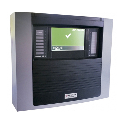
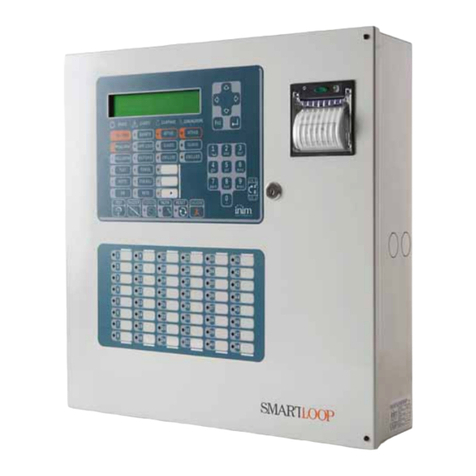
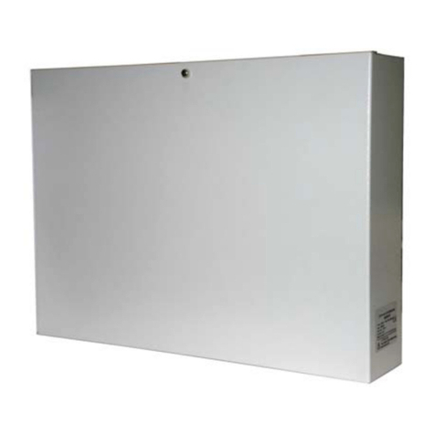
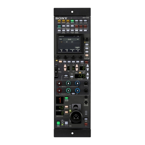
FC501 Fire Control Panel
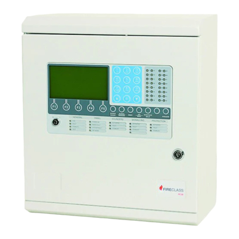
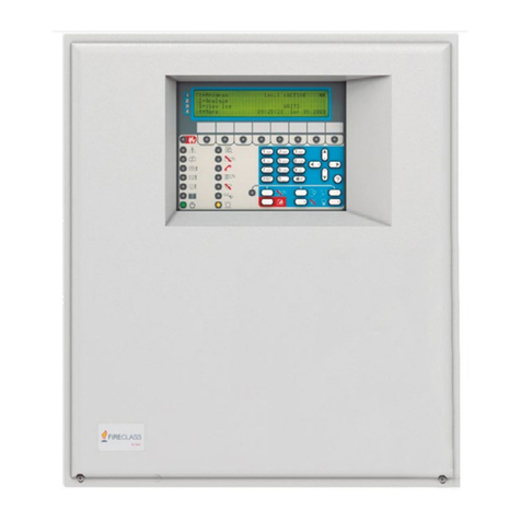
The FC501 is available in the following models:
ØFC501-L - Addressable Control Panel with 3 different
and isolated loops, that can support up to 128 ad-
dressable devices and 32 zones.
Power Supply: Switching power supply BAW50T24
(1.8 A @ 27.6 V).
Suitable Batteries: 2 * 12 V/ 7Ah
2 * 12 V/ 12Ah.
User Interface with Icons.
ØFC501-H - Addressable Control Panel with 3 differ-
ent and isolated loops, that can support up to 128 ad-
dressable devices and 32 zones.
Power Supply: Switching power supply BAW75T24
(2,7 A @ 27,6 V).
Suitable Batteries: 2 * 12 V/ 12Ah
2 * 12 V/ 38Ah
User Interface with LEDs descriptions in English.
ØFC501-HK: Analogue addressable Fire Control Panel
with 3 Loops, that can support up to 128 addressable
device and 32 zones.
Powered: BAW75T24 Switching Power Supply (2.7
A @ 27.6V).
Suitable batteries: 2 * 12 V/ 12Ah
2 * 12 V/ 38Ah
User Interface with Icons.
+In this manual, the term FC501 is used to describe
the characteristics common to all versions while
the version name is used to describe the differ-
ences between the versions listed above
FC501 The FC501 control panel is a modular system.
The configuration of the FC501 system depends on the
size and requirements of the application, therefore,
some of the described devices and functions may not
be present on your system.
The FC501 system consists of:
one FC501 control panel,
max 4 FC500REP Repeaters,
max 4 FC500MFI Multifunction Modules,
max 128 devices in three different loops or 128 max in a
single loop only.
The FC501 control panel allows users to manage the
functions of the Fire control system up to 2000 m (Loop)
with shielded cable 2 cores 2x2.5 csa.
nAccessory items
FC500REP Repeater Repeaters are peripherals that
provide all the system status information, emit audible
signals and allow users to control the functions of the
FC501 system (up to 1000 m, with double twist shielded
cable).
FC500MFI FC500MFI is a Programmable Multi func-
tional Module for connection of a real time event printer;
The terminal blocks also make it possible to connect a
“standard interface” to remotely control and manage a
set of Inputs and Outputs to control the panel.
FC500IP Module to connect the control panel to a LAN.
FireClass Console This user-friendly software appli-
cation (Microsoft Windows XP & above) offers a quick
and easy way to program the Control panel and pro-
vides event log and print-out functions.
User Access Level
L1=Access level 1: Viewing: everybody can view the
Control panel status. In detail:
-ANALYZE shows the status of the: 1- LOOP, 2- DEVICE, 3-
SW ZONES, 4- OUTPUTS, 5- NETWORK, 6- COMMUNIC.,
7- OPTIONS, 8- LOG and 9- FW Vers, 0-Panel.;
-VIEW LOG shows the LOG;
-VIEW LISTS shows the lists of: 1- DIS. ZONES, 2- DIS.
DEVICES, 3- DIS. PARTS, 4- WALK TEST, 5-
FAULTS, 6- WARNINGS and 7- DEV. in TEST.
L2=Access level 2 or User Level: Operating the sys-
tem (Access Code entered : ONLY Access Code can
operate the system). At this Level, all the operations at
access LEVEL 1 are available and in addition:
-MODIFY for: 1- INIT. MSG, 2-USER PASSWORD, 3-
DAY/NIGHT, 4- TIME and DATE, 5- Clear LOG, 6-
ZONE WALK TEST.
-DISABLE for: 1- Dis.LISTS, 2- DEVICES, 3- SW
ZONES, 4- OUTPUTS, 5- NETWORK, 6-
COMMUNIC., 7- PASSWORD, 8- FIRE relay.
INTRODUCTION 5


