manuals.online logo
Brands
  1. Home
  2. •
  3. Brands
  4. •
  5. Murphy
  6. •
  7. Controllers
  8. •
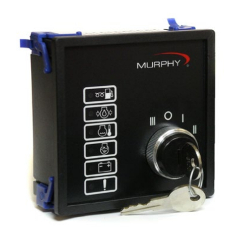
  9. Murphy Keystart 9700 User manual

Murphy Keystart 9700 User manual

KEYSTART 9700 series
MANUAL START ENGINE CONTROLLER WITH
AUTOMATIC FAULT PROTECTION SHUTDOWN
The Keystart 9700 range provides for the manual starting and
stopping of a standby engine - a generator, pump or other
application - with automatic monitoring and shutdown of the
engine in the event of a fault.
The 9700 series is pin compatible with the Autostart range:
this allows the use of standard wiring for both manual and
automatic control panels, simplifying panel design and
permitting easy upgrades from a manual to fully automatic
control system.
Key features
•Keyswitch operation for enhanced security
•Up to four fault inputs, configurable for use with contacts
which open or close on fault, with wiring to +ve or –ve DC
•Options for overspeed protection (magnetic pickup or
AC alternator driven) and preheat/auxiliary control.
•Pin compatible with Autostart 705, 710, 720 and 730 series.
•96 x 96mm DIN standard, front panel mounted case
•Switchable 12 or 24 V DC power supply
Operation
The Keystart is powered from the engine battery or similar
low voltage DC source. A switch at the rear allows for 12V
or 24V operation.
Control of the Keystart and engine is by use of a 3 or 4
position keyswitch on the front facia:-
STOP Removes power from the Keystart, stopping the
engine and resetting a latched fault condition.
RUN Energises the Keystart’s RUN relay (enabling
the engine fuel or ignition). The fault ‘override’
timer begins as soon as the key is turned (or
spring returns) to this position. Once the engine
is fully running, Keystart monitors for faults and
shuts down the engine if a fault is detected.
START
Maintains fuel to the engine, and activates the
START output (used for controlling the starter
motor circuit). This position is spring-biased to
return to the RUN position when the operator
releases the key.
AUX (optional: 'A' models only) Provides a switched
+ve DC output, used for preheat circuits or
auxiliary control (remote power up) of Keystart.
The key is common to all Keystarts and is removable
only in the STOP position.
The front facia also has five LED and pictogram indicators
for the display of engine fault status:-
Low Oil Pressure
High Engine Temperature
Overspeed (or Plant Fail on non-overspeed units)
Charge Fail
Plant Fail
The Generator Controls Division of
R
M010901
Issue 5, revised 04/99
Catalogue section 75
Product Specifications
Power supply:
Operating voltage:
Steady state
Brown out / cranking
(12V setting)
9 – 20 V DC
<= 5V for 2 secs
(24V setting)
18 – 33 V DC
<= 10V for 2 secs
Current consumption < 150mA
Inputs:
Fault switch inputs:- selectable: open or closed, + ve or – ve
+ ve input defined as:
– ve input defined as: 80% to 100% of +ve DC supply
–1V to +2V w.r.t –ve DC supply
Speed sensing inputs:-
Magnetic pickup
AC alternator 10 – 60 VAC peak, < 2300 to > 3400 Hz.
90 – 350 VAC rms, < 50 to > 60 Hz. nom.
Outputs: (all ratings for resistive load)
Run relay output volt-free SPCO relay contacts
16 A max. @ 24V DC
Start output + ve DC (switched)
16 A max. @ 24V DC
Auxiliary/preheat output + ve DC (switched)
15 A max. @ 24V DC
Alarm output – ve DC (open collector transistor)
300mA max. @ 33V DC max.
Tachometer / calibration To suit 0 – 1 mA, 75 Ohm meter,
output = 0.75mA at rated engine speed
Adjustable settings:
Fault Override timer < 10 to > 30 secs.
Overspeed trip level < 100 to >130 % of calibrated speed
General:
Overall dimensions (w x h x d) 96 x 96 x 130 mm
Panel cut-out size DIN 92 x 92 mm
Weight approx. 500 g
Operating ambient temperature –10oC to +55oC
Case sealing IP22
Vibration 1G, 50 Hz to 5 kHz.
Chemical/fire case: glass filled Noryl,
self extinguishing, non-dripping.
facia: polycarbonate
In order to consistently bring you the highest quality, full featured products, we reserve the right to change our specifications and designs at any time.
Control Outputs
The following are provided:-
•Switched +ve RUN relay and START outputs, used for
controlling the engine fuel and starter motor circuits.
•A –ve DC (open collector transistor), common ALARM
output, used for remotely signalling a fault condition.
Fault protection and Alarm System
After the operator has started the engine and the fault
override timer has expired, the Keystart monitors for engine
and plant faults through remotely connected switch sensors.
Dedicated inputs are provided for Low Oil Pressure and
High Engine Temperature switch sensors. 1 or 2 additional
inputs may be used for general purpose ‘plant fail’ contacts.
Switches at the rear allow the inputs to be configured for
use with remote contacts which either open or close during
fault, with wiring polarity to either +ve or –ve DC.
The Keystart may optionally be fitted with an engine
overspeed trip, available in alternator sensing (generator
AC, 50/60Hz) or magnetic pickup sensing variants.
If any of the above faults occur, Keystart will:-
•turn off its RUN output (stopping the engine)
•indicate the fault on the appropriate front facia LED
•activate its Alarm output (to remotely signal that a
fault has occurred).
The automatic fault shutdowns operate on a first-up and
latching basis - subsequent faults are not indicated and the
displayed fault can only be cleared by switching the
Keystart to STOP.
Charge Fail Warning
A charge failure warning LED is provided for use with an
engine driven charge alternator. The charge alternator’s
WL terminal is connected to the Keystart, which will in turn
monitor the WL voltage and provide the alternator with
excitation current at engine start up.
Installation
The Keystart uses a DIN standard 96 x 96 mm casing,
designed for mounting in a control panel cut-out (92 x 92mm
DIN). Electrical connection is through a pair of ‘two-part’
type terminal blocks at the rear of the unit, with 2 separate
¼” blade terminals on overspeed versions for the
tachometer or calibration meter.
Also at the rear is are 4 switches for the setting of the
supply voltage and alarm input configurations, and up to 3
potentiometers: one to set the fault ‘override’ time (all units),
and 2 more to set the speed calibration and overspeed trip
level, where fitted.
When ordering, please specify:–
a) Base unit type:-
Keystart 9700: no overspeed
Keystart 9701: magnetic pickup sensing overspeed
Keystart 9702: AC alternator (50/60Hz) overspeed
b) Options:-
‘A’: auxiliary control/preheat option
N.B: stock units are supplied with switch settings for 24VDC
power supply, inputs closing to –ve DC during fault.
Typical Connection Circuit
RPM/Calib.
Meter
L
N
– VE DC
+ VE DC
30
29
Start
Emergency
Stop
RUN
Run
Stop
Run
Remote
Start
(’A’ option only)
Start
+
22
23
4
1
–
fuel
alarm
starter
preheat
(’A’ option
only)
15
63
Plant Fail
HET
LOP
19
2
16
17
5
–
+
WL
RPH
RAL
Aux
RST
RFL
Generator AC
(KEY9702 only)
Magnetic pickup
(KEY9701 only)
15
Rear Facia Settings & Electrical Connection
– ve DC power supply
Charge fail input
+ve DC power supply
Aux. input ('A' option)
Mag. pickup input (KEY9701 only)
Alarm output: –ve DC, < 250mA
Aux./preheat output: +ve DC
('A' option only)
- No connection -
- No connection -
- No connection -
- No connection -
- No connection -
- No connection -
- No connection -
- No connection -
Note:–
Pin 5 is not used on models 9700 and 9702.
Pin 18 is not used on overspeed models 9701 and 9702.
Pins 29 and 30 are not used on models 9700 and 9701.
- No connection -
- No connection -
- No connection -
- No connection -
- No connection -
- No connection -
1
2
3
4
5
6
7
8
9
10
11
12
13
14
15
16
17
18
19
20
22
23
24
25
26
27
28
29
30
S1
Not
Used
Switch Settings(N.B. = up = down)
Fault Inputs:–
closed –ve
closed +ve
open –ve
open +ve
Supply:–
12 V DC
24 V DC
S2 S3S4
VR3: Fault override timer:–
< 10 to > 30 seconds
clockwise to increase
100 - 130% of nominal calibrated
speed, clockwise to increase
VR2: Overspeed trip level:–
With engine running at normal
speed, adjust VR1 until calibration
meter reads 0.75mA.
VR1: Nominal speed calibration:–
Tachometer/calibration output:–
0 – 1mA into 75 meter
VR1
+ve–ve
VR2
VR3
Input 1: Low Oil Pressure
Input 2: High Engine Temp.
Input 3: Plant Fail (9700 only)
Input 4: Plant Fail
Fuel output: + ve DC, 16A max.
Start output: + ve DC, 15A max.
Generator AC: 90 - 300 VAC
(KEY9702 only)
L
N
Since 1939
Frank W. Murphy Manufacturer
PO Box 470248, Tulsa, Oklahoma 74147, USA
Tel: + 1 918 627 3550 Fax: + 1 918 664 6146
email: [email protected]
web: http://www.fwmurphy.com
Frank W. Murphy Southern Division
PO Box 1819, Rosenberg, Texas 77471, USA
Tel: + 1 281 342 0297 Fax: + 1 281 341 6006
email: [email protected]
Frank W. Murphy Ltd.
Incorporating Modex Automation
Church Road, Laverstock, Salisbury U.K.
Tel: + 44 1722 410055 Fax + 44 1722 410088
Pour service en Français, tél: + 44 1722 410697
email: [email protected]
web: http://www.fwmurphy.co.uk
Murphek Pty. Ltd.
1620 Hume Highway, Campbellfield, Vic. 3061 Australia
Tel: + 61 3 9358 5555 Fax: + 61 3 9358 5558
email: [email protected]
Murphy Switch of California
PO Box 900788, Palmdale, California 93590, USA
Tel: + 1 805 272 4700 Fax: + 1 805 947 7570
email: [email protected]
web: http://www.murphyswitch.com
Murphy de Mexico S.A. de C.V.
Blvd. Antonio Rocha Cordero 300, Fracción del Aguaje
San Luis Potosí, S.L.P. México 78384
Tel: + 52 48 206264 Fax: + 52 48 206336
email: [email protected]
Frank W. Murphy Pte, Ltd.
No. 2 Tuas South Street 2, Sprintecs Building
02-01/02, Singapore 637895
Tel: + 65 863 1398 Fax: + 65 863 0208
email: [email protected]
Frank W. Murphy Ltd. en France
Tel: +33 (1) 30 76 26 26 Fax: +33 (1) 30 76 39 89
Direct usine Tel: + 44 1722 410697
email: [email protected]

This manual suits for next models

1

Other Murphy Controllers manuals

Murphy CONNECT User manual

Murphy

Murphy CONNECT User manual

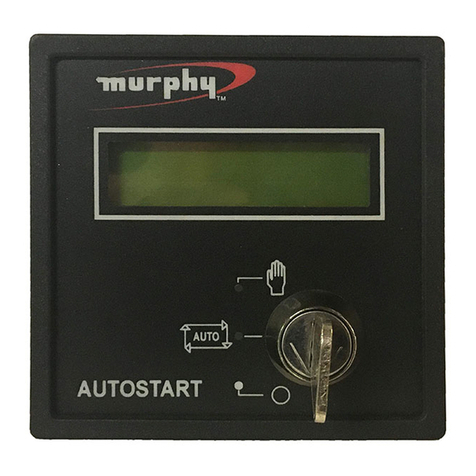
Murphy Automatic Engine Controller A88 User manual

Murphy

Murphy Automatic Engine Controller A88 User manual

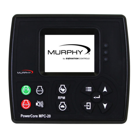
Murphy PowerCore MPC-20 User manual

Murphy

Murphy PowerCore MPC-20 User manual

Murphy Autostart AS731 User manual

Murphy

Murphy Autostart AS731 User manual

Murphy LR857 User manual

Murphy

Murphy LR857 User manual

Murphy Automatic Engine Controller AS3000 User manual

Murphy

Murphy Automatic Engine Controller AS3000 User manual

Murphy Centurion Configurable Controller CE-05171N User manual

Murphy

Murphy Centurion Configurable Controller CE-05171N User manual

Murphy EMS447 User manual

Murphy

Murphy EMS447 User manual

Murphy Automatic Engine Controller EA150 User manual

Murphy

Murphy Automatic Engine Controller EA150 User manual

Murphy EMS547 User manual

Murphy

Murphy EMS547 User manual

Murphy Autostart 710 AS710S User manual

Murphy

Murphy Autostart 710 AS710S User manual

Murphy Cascade CD101 User manual

Murphy

Murphy Cascade CD101 User manual

Murphy EMS PRO User manual

Murphy

Murphy EMS PRO User manual

Murphy Cascade CD101 User manual

Murphy

Murphy Cascade CD101 User manual

Murphy LR579 User manual

Murphy

Murphy LR579 User manual

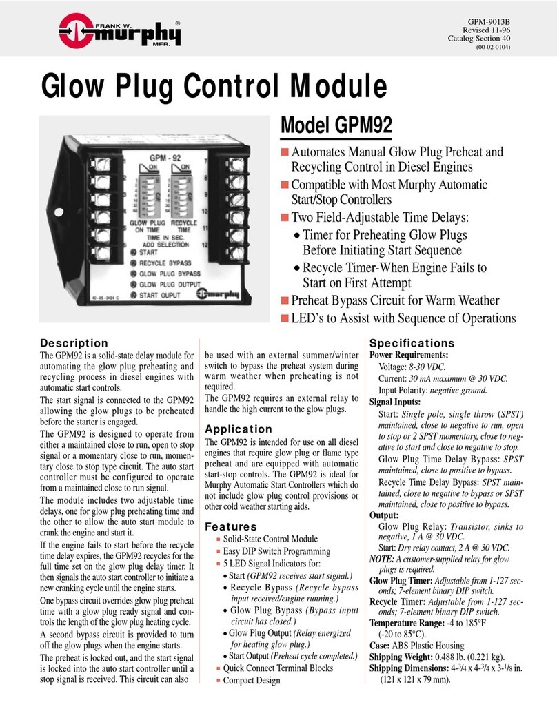
Murphy Glow Plug Control Module GPM92 User manual

Murphy

Murphy Glow Plug Control Module GPM92 User manual

Murphy Autostart 705 AS705S User manual

Murphy

Murphy Autostart 705 AS705S User manual

Murphy iGUARD User manual

Murphy

Murphy iGUARD User manual

Murphy PowerCore TEC-10 User manual

Murphy

Murphy PowerCore TEC-10 User manual

Murphy Selectronic Micro-Controller Series 1500 User manual

Murphy

Murphy Selectronic Micro-Controller Series 1500 User manual

Murphy Auto-Start/Stop Controller Cascade User manual

Murphy

Murphy Auto-Start/Stop Controller Cascade User manual

Murphy MX4 Series User manual

Murphy

Murphy MX4 Series User manual

Murphy PowerCore MGC1000 User manual

Murphy

Murphy PowerCore MGC1000 User manual

Murphy Autostart 730 AS730 User manual

Murphy

Murphy Autostart 730 AS730 User manual

Popular Controllers manuals by other brands

Hamworthy TYNEHAM AHP60 14/18 Installation, commissioning and servicing instructions

Hamworthy

Hamworthy TYNEHAM AHP60 14/18 Installation, commissioning and servicing instructions

Sanhua EEV SEC61 SERIES quick start guide

Sanhua

Sanhua EEV SEC61 SERIES quick start guide

Zanotti DFZ Description and Operation Manual

Zanotti

Zanotti DFZ Description and Operation Manual

Trox Technik AURASAFE mini Guide

Trox Technik

Trox Technik AURASAFE mini Guide

PG Drives Technology SK79649-01 Technical manual

PG Drives Technology

PG Drives Technology SK79649-01 Technical manual

Texas Instruments bq78350-R1 Technical reference

Texas Instruments

Texas Instruments bq78350-R1 Technical reference

STORK TRONIC ST96 Series Wiring diagram

STORK TRONIC

STORK TRONIC ST96 Series Wiring diagram

United Automation PR3-E SPM Series manual

United Automation

United Automation PR3-E SPM Series manual

CBi electric Astute instruction manual

CBi electric

CBi electric Astute instruction manual

AmerTac SLC6 instructions

AmerTac

AmerTac SLC6 instructions

Omron SYSMAC C200HS installation guide

Omron

Omron SYSMAC C200HS installation guide

WEG SSW07 Series user manual

WEG

WEG SSW07 Series user manual

iSMA iSMA-B-FCU Series user manual

iSMA

iSMA iSMA-B-FCU Series user manual

Weil-McLain WMZV-4 instruction manual

Weil-McLain

Weil-McLain WMZV-4 instruction manual

Asus LSI 8300XLP user manual

Asus

Asus LSI 8300XLP user manual

LinMot B1100-PP installation guide

LinMot

LinMot B1100-PP installation guide

Epson S1R75801F00A Technical manual

Epson

Epson S1R75801F00A Technical manual

SEW movifit mc operating instructions

SEW

SEW movifit mc operating instructions

manuals.online logo
manuals.online logoBrands
  • About & Mission
  • Contact us
  • Privacy Policy
  • Terms and Conditions

Copyright 2025 Manuals.Online. All Rights Reserved.