manuals.online logo
Brands
  1. Home
  2. •
  3. Brands
  4. •
  5. Murphy
  6. •
  7. Controllers
  8. •
  9. Murphy Cascade CD101 User manual

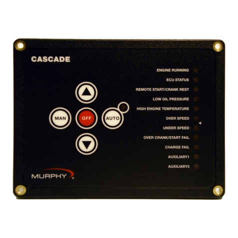
Murphy Cascade CD101 User manual

MURPHY, the Murphy logo, Cascade, and SWICHGAGE(r) are registered and/or common law trademarks of
Murphy Industries, Inc.
This document, including textual matter and illustrations, is copyright protected by Murphy Industries, Inc.,
with all rights reserved. (c) 2004 Murphy Industries, Inc.
Installation 00-02-0594 page 1 of 12
Cascade CD101 Auto-Start Controller
Installation and Operations Manual Version: 2.00
00-02-0594
Effective 10-07
Section 40 & 75
Description
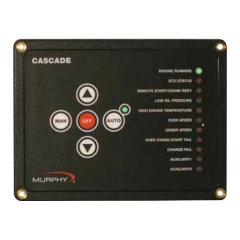
The Cascade controller offers automatic start/stop control with easy configuration for
a broad number of engine driven applications.
Specifications
Power input: 9-35VDC continuous - operates during total blackout for 2 sec. min.
Power consumption: Sleep Mode (Manual): 1mA typical;(Automatic) 4mA typical.
Running Mode (Manual): 20mA typical; (Automatic): 24mA typical.
Operating/Storage temperature: -40 to 85°C; (-40 to 185°F).
Humidity: 0-100%, non-condensing.
Housing: UV stabilized black polycarbonate and epoxy encapsulation. Weather tight
and includes sealing gasket to keep moisture and debris out of enclosure. Properly
mounted controller will maintain NEMA4 / IP65 rating of enclosure.
Vibration: Rated to 6G.
Impact: Rated to 10G.
Inputs: Dedicated digital inputs for low oil pressure, high engine temperature,
remote start, DC charge fail/Alternator fail. Two aux inputs are configurable for mul-
tiple functions.
Outputs: 7 – 4 auxiliary, configurable (1A DC protected). 3 dedicated outputs for
Crank, Fuel/ECU, Alternator excitation.
Crank attempts: 3, 5, 10, Continuous.
Crank Rest: 5-60 seconds, adjustable.
Shutdown lockout time delay: 5, 10, 15, 20, 25, 30 seconds.
Crank disconnect speed setting: Field settable 0-9999 RPM (16-60Hz AC freq input).
Overspeed/underspeed trip point setting: ±5 to 50% of nominal.
Speed sensing inputs: Magnetic pickup (5-120VAC RMS / 0-10 kHz) & AC fre-
quency (30-600VAC RMS / 16-80 Hz).
CANbus interface: Directly reads engine speed, & engine status data* from SAE-
J1939 enabled engines.
MODbus interface: In J1939 applications drives PVA series analog gages
*Engine status data limited to low oil pressure, high engine temperature, “Wait to
start” status, Warning & Fault lamp information, and communication error.
To Install, You Will Need:
#2 Phillips (cross head) head screwdriver
Nut driver to fit #6-32x1/2” machine nuts
Wire for hook-up (rising cage clamp suitable for 14-24 gage wire).
Mounting the Cascade
Cut a 5.63 x 4.06 in. (143 x 103mm) mounting hole, and drill four 0.169 in.(4.3 mm)
diameter holes for the mounting screws. See Schematic below:
Recommended Wiring Practices
1. To help prevent electrical noise and voltage drop to the controller during cranking
and preheat, wire the controller DC power connections directly to the cranking
battery. This will also help improve “Low battery” starting capability.
2. When using a battery charger, it should be connected directly to the battery to
help prevent electrical noise which could cause an engine ECU or associated
equipment to operate erratically.
3. Never route low voltage DC wiring in the same conduit as high voltage AC
wiring. Noise from electrical loads such as motors and variable frequency drives
can be coupled into the engine ECU, governor, or associated equipment and may
cause erratic operation.
4. Always use twisted shielded pair wires for the magnetic pickup wiring. Ground one
end of the shield only.
5. In spark ignited engine applications, always use resistive spark plugs and spark
plug wires, as these greatly reduce the amount of radiated noise.
6. Always place a snubbing diode (sometimes also called an anti-flyback, anti-kick-
back or reverse bias diode) directly across any inductive load. This helps elimi-
nate a common source of electrical noise, as well as increases the operating life-
time of any solid state output.
7. Always use twisted shielded pair communications wiring for RS-485, and SAE
standard wire for J1939. Make sure that terminating resistors (if required) have
the correct rating and are installed properly.
Please read the following information before installing. A visual inspection of this product for damage during shipping
is recommended before mounting. It is your responsibility to have a qualified person install this unit and make sure it con-
forms to NEC and local codes.
GENERAL INFORMATION
Warning: The CASCADE is designed for pilot-duty use and its outputs are for
control only. Wire the CASCADE controller with 18 gage stranded wire.
Important: For applications involving automatic start equipment, we strongly
recommend the installation of an appropriate Emergency Stop device.
WARNING
BEFORE BEGINNING INSTALLATION OF THIS MURPHY PRODUCT
✔✔Disconnect all electrical power to the machine.
✔✔Make sure the machine cannot operate during installation.
✔✔Follow all safety warnings of the machine manufacturer.
✔✔Read and follow all installation instructions.
Cut Out Dimensions
Gasket
OPEN
1 2 3 4
6.57 in. (167 mm)
6.06 in. (154 mm)
5.63 in. (143 mm)
5.63 x 4.06 in. (143 x 103 mm).
4.49 in. (114 mm)
4.06 in. (103 mm)
5.00 in. (127 mm)
0.169 in. (4.3 mm)
diameter4 places
Remote call to run12
Aux. 2 in11
Aux. 3 out 13
Aux. 4 out 14
Not used15
Aux. 1 in10
Hi engine temp. 9
Lo oil press. 8
ACLine
ACNeutral
Mag. Pickup +
Mag. Pickup –
Alt. Excite. 7
Aux. 2 out 6
Aux. 1 out 5
Crank 4
Fuel/ECU 3
-V Batt. 2
+V Batt. 1
24 25 26 27
LISTED LISTED
E236550
R
CUS
Installation 00-02-0594 page 2 of 12
LED Status Lights
Eleven LEDs separated into two banks (see “Fig. 1”) are provided on the faceplate.
The LEDs Bank 1 includes 6 LEDs and Bank 2 includes 5. In Setup mode, these
banks form a binary code to indicate either the controller setup configuration or error
status, which is indicated by the last 8 (red) LEDs. Refer to Tables 1, 2, 3 and 4 for
configuration and status listings.
One LED is located next to the “AUTO” button to indicate that the controller is wait-
ing for the remote start input to become active.
The LED status light are (from top to bottom) see “Fig. 1”:
Engine running - If the green LED is ON, then the unit is receiving a speed signal,
indicating that the engine is above the crank cut speed.
ECU status - If the green LED is on solid, it indicates that in a J1939 application the
ECU and the unit are communicating properly. If the LED is blinking slowly the
ECU is broadcasting a “wait to start” message. If the LED is blinking fast, the
ECU is NOT communicating properly.
Remote Start/ Crank Rest - If the green LED is on, then the remote start input is
active and if the system is in AUTO mode, it will try to start. If the LED is blink-
ing, the crank cycle has ended and is now in crank rest cycle.
Low oil pressure - If the red LED is on, the controller has caused the engine to shut-
down and lockout. If the LED is blinking, the engine ECU has transmitted a SPN
for an oil pressure related condition.
High Engine Temperature - If the red LED is on, the controller has caused the
engine to shutdown and lockout. If the LED is blinking, the engine ECU has trans-
mitted a SPN for an engine temperature related condition.
Overspeed - If the red LED is on, the controller has caused the engine to shutdown
and lock out due to engine speed exceeding the setpoint.
Underspeed - If the red LED is on, the controller has caused the engine to shutdown
and lock out due to engine speed falling below the minimum needed for proper
operation.
Overcrank - If the red LED is on, the controller has exceeded the set number of start
attempts without receiving a valid speed signal indicating that engine speed is
above crank disconnect. This causes the engine to shutdown and lockout.
Charge Fail - If the red LED is on it indicates that the battery charging alternator is
not charging the cranking batteries, or that the battery charger fail output is on.
Aux 1 - If the red LED is on it indicates that this custom-configured input is active.
On an ECU (ECM) equipped engine, if this LED is blinking slowly, it indicates
that one or more engine parameters are near exceeding engine manufacturer’s set-
points. If the LED is blinking fast, it indicates that one or more engine parameters
have exceeded setpoints, the ECU has issued a fault - and most likely the engine
has shut down.
Aux 2 - If the red LED is on it indicates that this custom-configured input is active.
Overspeed & Underspeed - If these two LED’s are both blinking, the controller has
lost its speed signal.
Setting Up the Cascade
●
To enter the SETUP MODE first remove DC
power to the Cascade controller for approximately
10 seconds.
●
On the back of the controller are four DIP switch-
es, set switch #1 to ON (see schematic at right)
then restore DC power. The AUTO mode LED
will blink to indicate that the Cascade is in the
SETUP MODE.
●
When in the “SETUP” mode, pressing the “MAN”
(Manual) button steps up thru the entire list of parameters. The pattern of the top
six LEDs, LEDs Bank 1 (see “Fig. 1”), is used to indicate which parameter is
selected. The pattern will change once each time the “MAN” button is pressed.
●
Pressing the “OFF” button steps up thru all the available values for each parameter.
The pattern of the bottom five LEDs, LEDs Bank 2 (see “Fig. 1”), is used to indi-
cate which value is selected. The pattern will change once each time the OFF but-
ton is pushed.
●
Pressing the “AUTO” button stores the displayed value.
●
If any value is changed, it will blink until
stored, except a value of zero. If any value
is changed but not stored, and then the
parameter is changed, the value will still
be what was shown originally.
●
If you accidentally go past a desired para-
meter or value, you can step back by press-
ing the down arrow button.
●
The parameter/value list and correspond-
ing LED indication are shown on Table 1.
●
When you are finished with setup, set switch #1 to in the Normal Operating
Position (OPEN), remove DC power for 10 seconds, then restore DC power.
Operating the Cascade
When power is first applied, all LEDs will flash indicating a Lamp Test function.
●
To manually start the engine, press the “MAN” (Manual) button. The controller
will initiate a normal start sequence.
●
To manually stop the engine (or turn off the controller) press the “OFF” button.
●
To place the controller in automatic mode, press the button labeled “AUTO”. The
LED next to the “AUTO” button should come on to indicate that the controller is
waiting for the remote start input to become active to initiate a start sequence.
●
To reset the controller, press the “OFF” button. Then correct the cause of the shut-
down. This will clear all faults except when the aux inputs are programmed for
either shutdown immediate or warning immediate, or if the engine ECU is broad-
casting a shutdown fault.
In the event of a fault that causes the engine to shutdown, the cause of the event will
be indicated on one of the 11 status lights on the right hand side of the controller.
When the cause of shutdown is corrected,the controller can resume normal operation.
Modes of Operation
Setup Mode (See “Setting Up The Cascade” section, above and “Table 1”).
Normal Operating Mode (Engine Control Mode)
The DIP switch #1 must be in the open position in order to enter this mode upon
power up. The “Table 2” shows the meaning of each LED state for this mode.
Error Mode
Upon power up, when the DIP switch #1 is in the Normal Operating Position (open
position) and an error is detected in the user configuration, the Error mode will be
accessed. The LEDs will Blink Fast indicating the error. To correct the errors before
the unit can operate in Engine Control mode, the user will need to go back to Setup
mode. “Tables 3 and 4” show the meaning of each LED state and configuration for
the Error mode.
MAN
AUTO
OFF
AMO
AUTO Mode
LED
AMO
ENGINE RUNNING
ECU STATUS
REMOTE START/CRANK REST
LOW OIL PRESSURE
HIGH ENGINE TEMPERATURE
OVERSPEED
UNDERSPEED
OVERCRANK/START FAIL
CHARGE FAIL
AUXILIARY1
AUXILIARY2
LED’s
LEDs
Bank 1
LEDs
Bank 2
Parameter#Value
OPEN
1 2 3
Move Switch toward
the numbers to Turn On
NOTE: Switch settings are
read at PowerUp only.
4
Fig. 1
Fig. 2
Fig. 3
Installation 00-02-0594 page 3 of 12
# Description LED Bank 1 Value (*= default) LED Bank 2
1Engine Speed Source
❍❍❍❍❍●
Magnetic Pickup*
❍❍❍❍❍
Generator AC
❍❍❍❍●
J1939 (ECU)
❍❍❍●❍
2 Crank Attempts
❍❍❍❍●❍
3*
❍❍❍❍❍
5
❍❍❍❍●
10
❍❍❍●❍
Continuous
❍❍❍●●
3 Crank Timer
❍❍❍❍●●
5 Sec
❍❍❍❍❍
10 Sec
❍❍❍❍●
15 Sec*
❍❍❍●❍
20 Sec
❍❍❍●●
25 Sec
❍❍●❍❍
30 Sec
❍❍●❍●
45 Sec
❍❍●●❍
60 Sec
❍❍●●●
4 Crank Rest Timer
❍❍❍●❍❍
5 Sec
❍❍❍❍❍
10 Sec
❍❍❍❍●
15 Sec*
❍❍❍●❍
20 Sec
❍❍❍●●
25 Sec
❍❍●❍❍
30 Sec
❍❍●❍●
45 Sec
❍❍●●❍
60 Sec
❍❍●●●
5 Start Delay Timer
❍❍❍●❍●
0 Sec*
❍❍❍❍❍
(auto mode only) 5 Sec
❍❍❍❍●
10 Sec
❍❍❍●❍
15 Sec
❍❍❍●●
30 Sec
❍❍●❍❍
60 Sec
❍❍●❍●
6 Stop Delay Timer
❍❍❍●●❍
0 Sec*
❍❍❍❍❍
(auto mode only) 5 Sec
❍❍❍❍●
10 Sec
❍❍❍●❍
15 Sec
❍❍❍●●
30 Sec
❍❍●❍❍
60 Sec
❍❍●❍●
7 Preheat Timer
❍❍❍●●●
0 Sec*
❍❍❍❍❍
5 Sec
❍❍❍❍●
10 Sec
❍❍❍●❍
15 Sec
❍❍❍●●
20 Sec
❍❍●❍❍
25 Sec
❍❍●❍●
30 Sec
❍❍●●❍
45 Sec
❍❍●●●
60 Sec
❍●❍❍❍
8 Extended Preheat
❍❍●❍❍❍
0 Sec*
❍❍❍❍❍
during Crank (only used if 5 Sec
❍❍❍❍●
preheat timer is also set 10 Sec
❍❍❍●❍
to a non-zero value) 15 Sec
❍❍❍●●
20 Sec
❍❍●❍❍
(must be less than or 25 Sec
❍❍●❍●
equal to crank timer) 30 Sec
❍❍●●❍
45 Sec
❍❍●●●
60 Sec
❍●❍❍❍
9 Warmup Timer
❍❍●❍❍●
0 min.*
❍❍❍❍❍
1 min.
❍❍❍❍●
5 min.
❍❍❍●❍
10 min.
❍❍❍●●
10 Cooldown Timer
❍❍●❍●❍
0 min.*
❍❍❍❍❍
1 min.
❍❍❍❍●
5 min.
❍❍❍●❍
10 min.
❍❍❍●●
11 Bypass Timer
❍❍●❍●●
0 Sec
❍❍❍❍❍
5 Sec
❍❍❍❍●
10 Sec*
❍❍❍●❍
15 Sec
❍❍❍●●
20 Sec
❍❍●❍❍
25 Sec
❍❍●❍●
30 Sec
❍❍●●❍
12 Energize to Stop
❍❍●●❍❍
15 Sec*
❍❍❍❍❍
Timer 30 Sec
❍❍❍❍●
# Description LED Bank 1 Value (*= default) LED Bank 2
13 Aux Input Bypass
❍❍●●❍●
30 Sec*
❍❍❍❍❍
Timer 1 Min
❍❍❍❍●
2 Min
❍❍❍●❍
3 Min
❍❍❍●●
4 Min
❍❍●❍❍
5 Min
❍❍●❍●
6 Min
❍❍●●❍
7 Min
❍❍●●●
8 Min
❍●❍❍❍
9 Min
❍●❍❍●
10 Min
❍●❍●❍
15 Min
❍●❍●●
20 Min
❍●●❍❍
25 Min
❍●●❍●
30 Min
❍●●●❍
35 Min
❍●●●●
40 Min
●❍❍❍❍
45 Min
●❍❍❍●
50 Min
●❍❍●❍
55 Min
●❍❍●●
1 Hr
●❍●❍❍
14 Cranking Motor
❍❍●●●❍ Disabled* ❍❍❍❍❍
Abutment Protection Delay 1.00 s
❍❍❍❍●
(Current crank attempt is 1.25 s
❍❍❍●❍
aborted if an RPM greater 1.50 s
❍❍❍●●
than 10 is not detected 1.75 s
❍❍●❍❍
after this delay from start 2.00 s
❍❍●❍●
of crank has expired) 2.25 s
❍❍●●❍
2.50 s
❍❍●●●
(MPU and J1939 speed 2.75 s
❍●❍❍❍
source only) 3.00 s
❍●❍❍●
3.25 s
❍●❍●❍
3.50 s
❍●❍●●
3.75 s
❍●●❍❍
4.00 s
❍●●❍●
4.25 s
❍●●●❍
4.50 s
❍●●●●
4.75 s
●❍❍❍❍
5.00 s
●❍❍❍●
15 Remote Start Signal
❍❍●●●●
Maintained*
❍❍❍❍❍
Type Momentary
❍❍❍❍●
16 Digital Input 1
❍●❍❍❍❍
Lo Oil Press (Open/Fault)
❍❍❍❍❍
Lo Oil Press (Close/Fault)*
❍❍❍❍●
17 Digital Input 2
❍●❍❍❍●
Hi Eng Temp (Open/Fault)
❍❍❍❍❍
Hi Eng Temp (Close/Fault)*
❍❍❍❍●
18 Digital Input 3
❍●❍❍●❍
Not Used*
❍❍❍❍❍
(Auxiliary Input 1) Winter/Summer
❍❍❍❍●
Momentary Stop
❍❍❍●❍
Immediate Warning
❍❍❍●●
Delayed Warning
❍❍●❍❍
Immediate Shutdown
❍❍●❍●
Delayed Shutdown
❍❍●●❍
Delayed Aux Input Shtdwn
❍❍●●●
Run/Idle (Line Fill)
❍●❍❍❍
Auxiliary Crank Disconnect
❍●❍❍●
Remote Reset (Clear Faults)
❍●❍●❍
19 Digital Input 4
❍●❍❍●●
Not Used*
❍❍❍❍❍
(Auxiliary Input 2) Winter/Summer
❍❍❍❍●
Momentary Stop
❍❍❍●❍
Immediate Warning
❍❍❍●●
Delayed Warning
❍❍●❍❍
Immediate Shutdown
❍❍●❍●
Delayed Shutdown
❍❍●●❍
Delayed Aux Input Shtdwn
❍❍●●●
Run/Idle (Line Fill)
❍●❍❍❍
Auxiliary Crank Disconnect
❍●❍❍●
Remote Reset (Clear Faults)
❍●❍●❍
22 Fuel Relay Control
❍●❍●●❍
Energized to Run*
❍❍❍❍❍
(non ECU Engines) Note: Energized to Stop
❍❍❍❍●
On ECU engines, fuel relay
is used for ECU power
Table 1. Parameter Values and Corresponding LED Indication
LEDs shown here form a binary code indicating the configuration value. Shown from Top to bottom the LEDs read from Left to Right (see Fig.1). A filled dot means LED is ON.
Parameter Parameter
Table 1. Parameter Values and Corresponding LED Indication
(continued)
LEDs shown here form a binary code indicating the configuration value. Shown from Top to bottom the LEDs read from Left to Right (see Fig.1). A filled dot means LED is ON.
Installation 00-02-0594 page 4 of 12
# Description LED Bank 1 Value (*= default) LED Bank 2
23 Auxiliary Output 1
❍●❍●●●
Not Used*
❍❍❍❍❍
Warmup
❍❍❍❍●
Cooldown
❍❍❍●❍
Warmup/Cooldown
❍❍❍●●
Preheat
❍❍●❍❍
Engine Running
❍❍●❍●
At Load
❍❍●●❍
Lo Oil Press Shutdown
❍❍●●●
Hi Eng Temp. Shutdown
❍●❍❍❍
Overspeed Shutdown
❍●❍❍●
Overcrank Shutdown
❍●❍●❍
Alternator Fail/Battery
High/Low/Weak
❍●❍●●
Engine Speed Up
❍●●❍❍
Engine Speed Down
❍●●❍●
Common Alarm
❍●●●❍
Controller in
AUTO mode ❍●●●●
Shutdown ●❍❍❍❍
Loss of Speed
Signal Fault ●❍❍❍●
Underspeed Fault
●❍❍●❍
24 Auxiliary Output 2
❍●●❍❍❍
Not Used*
❍❍❍❍❍
Warmup
❍❍❍❍●
Cooldown
❍❍❍●❍
Warmup/Cooldown
❍❍❍●●
Preheat
❍❍●❍❍
Engine Running
❍❍●❍●
At Load
❍❍●●❍
Lo Oil Press Shutdown
❍❍●●●
Hi Eng Temp. Shutdown
❍●❍❍❍
Overspeed Shutdown
❍●❍❍●
Overcrank Shutdown
❍●❍●❍
Alternator Fail/Battery
High/Low/Weak
❍●❍●●
Engine Speed Up
❍●●❍❍
Engine Speed Down
❍●●❍●
Common Alarm
❍●●●❍
Controller in
AUTO mode ❍●●●●
Shutdown ●❍❍❍❍
Loss of Speed
Signal Fault ●❍❍❍●
Underspeed Fault
●❍❍●❍
25 Auxiliary Output 3
❍●●❍❍●
Not Used*
❍❍❍❍❍
Warmup
❍❍❍❍●
Cooldown
❍❍❍●❍
Warmup/Cooldown
❍❍❍●●
Preheat
❍❍●❍❍
Engine Running
❍❍●❍●
At Load
❍❍●●❍
Lo Oil Press Shutdown
❍❍●●●
Hi Eng Temp. Shutdown
❍●❍❍❍
Overspeed Shutdown
❍●❍❍●
Overcrank Shutdown
❍●❍●❍
Alternator Fail/Battery
High/Low/Weak
❍●❍●●
Engine Speed Up
❍●●❍❍
Engine Speed Down
❍●●❍●
Common Alarm
❍●●●❍
Controller in
AUTO mode ❍●●●●
Shutdown ●❍❍❍❍
Loss of Speed
Signal Fault ●❍❍❍●
Underspeed Fault
●❍❍●❍
26 Auxiliary Output 4
❍●●❍●❍
Not Used*
❍❍❍❍❍
Warmup
❍❍❍❍●
Cooldown
❍❍❍●❍
Warmup/Cooldown
❍❍❍●●
Preheat
❍❍●❍❍
Engine Running
❍❍●❍●
At Load
❍❍●●❍
# Description LED Bank 1 Value (*= default) LED Bank 2
Lo Oil Press Shutdown
❍❍●●●
Hi Eng Temp. Shutdown
❍●❍❍❍
Overspeed Shutdown
❍●❍❍●
Overcrank Shutdown
❍●❍●❍
Alternator Fail/Battery
High/Low/Weak
❍●❍●●
Engine Speed Up
❍●●❍❍
Engine Speed Down
❍●●❍●
Common Alarm
❍●●●❍
Controller in
AUTO mode ❍●●●●
Shutdown ●❍❍❍❍
Loss of Speed
Signal Fault ●❍❍❍●
Underspeed Fault
●❍❍●❍
28
Initial Power-Up ❍●●●❍❍ Power-Up in Manual* ❍❍❍❍❍
Mode Power-Up in
Automatic
❍❍❍❍●
29 Oil Pressure Crank
❍●●●❍● Not Used* ❍❍❍❍❍
Disconnect Delay 0 s
❍❍❍❍●
(non-ECU engines 0.25 s
❍❍❍●❍
only) 0.50 s
❍❍❍●●
0.75 s
❍❍●❍❍
1.00 s
❍❍●❍●
1.25 s
❍❍●●❍
1.50 s
❍❍●●●
1.75 s
❍●❍❍❍
2.00 s
❍●❍❍●
2.25 s
❍●❍●❍
2.50 s
❍●❍●●
2.75 s
❍●●❍❍
3.00 s
❍●●❍●
3.25 s
❍●●●❍
3.50 s
❍●●●●
3.75 s
●❍❍❍❍
4.00 s
●❍❍❍●
4.25 s
●❍❍●❍
4.50 s
●❍❍●●
4.75 s
●❍●❍❍
5.00 s
●❍●❍●
30 Nominal Generator
❍●●●●❍
50 Hz
❍❍❍❍❍
Frequency (genset only) 60 Hz*
❍❍❍❍●
31 Crank Disconnect
❍●●●●●
0
❍❍❍❍❍
Freq (Generator AC 1
❍❍❍❍●
speed source only) 2*
❍❍❍●❍
(10’s digit) 3
❍❍❍●●
4
❍❍●❍❍
5
❍❍●❍●
6
❍❍●●❍
32 Crank Disconnect
●❍❍❍❍❍
0*
❍❍❍❍❍
Freq. (Generator AC 1
❍❍❍❍●
speed source only) 2
❍❍❍●❍
(1’s digit) 3
❍❍❍●●
4
❍❍●❍❍
5
❍❍●❍●
6
❍❍●●❍
7
❍❍●●●
8
❍●❍❍❍
9
❍●❍❍●
33 Crank Disconnect
●❍❍❍❍●
0*
❍❍❍❍❍
RPM (ECU or MPU 1
❍❍❍❍●
speed source only) 2
❍❍❍●❍
(1000’s digit) 3
❍❍❍●●
4
❍❍●❍❍
5
❍❍●❍●
6
❍❍●●❍
7
❍❍●●●
8
❍●❍❍❍
9
❍●❍❍●
34 Crank Disconnect
●❍❍❍●❍
0
❍❍❍❍❍
RPM (ECU or MPU 1
❍❍❍❍●
speed source only) 2
❍❍❍●❍
Parameter Parameter
Installation 00-02-0594 page 5 of 12
# Description LED Bank 1 Value (*= default) LED Bank 2
(100’s digit) 3
❍❍❍●●
4
❍❍●❍❍
5*
❍❍●❍●
6
❍❍●●❍
7
❍❍●●●
8
❍●❍❍❍
9
❍●❍❍●
35 Crank Disconnect
●❍❍❍●●
0
❍❍❍❍❍
RPM (ECU or 1
❍❍❍❍●
MPU speed source 2
❍❍❍●❍
only) (10’s digit) 3
❍❍❍●●
4*
❍❍●❍❍
5
❍❍●❍●
6
❍❍●●❍
7
❍❍●●●
8
❍●❍❍❍
9
❍●❍❍●
36 Crank Disconnect
●❍❍●❍❍
0*
❍❍❍❍❍
RPM (ECU or MPU 1
❍❍❍❍●
speed source only) 2
❍❍❍●❍
(1’s digit) 3
❍❍❍●●
4
❍❍●❍❍
5
❍❍●❍●
6
❍❍●●❍
7
❍❍●●●
8
❍●❍❍❍
9
❍●❍❍●
37 Overspeed Setpoint
●❍❍●❍●
5%
❍❍❍❍❍
(% above run speed) 10%*
❍❍❍❍●
15%
❍❍❍●❍
20%
❍❍❍●●
25%
❍❍●❍❍
30%
❍❍●❍●
35%
❍❍●●❍
40%
❍❍●●●
45%
❍●❍❍❍
50%
❍●❍❍●
38 Underspeed
●❍❍●●❍
5%
❍❍❍❍❍
Setpoint (% below 10%
❍❍❍❍●
run speed 15%
❍❍❍●❍
20%*
❍❍❍●●
25%
❍❍●❍❍
30%
❍❍●❍●
35%
❍❍●●❍
40%
❍❍●●●
45%
❍●❍❍❍
50%
❍●❍❍●
39 Underspeed
●❍❍●●●
None
❍❍❍❍❍
Response Warning*
❍❍❍❍●
Shutdown
❍❍❍●❍
40 Lo Oil Press
●❍●❍❍❍
Disabled (no shutdown)
❍❍❍❍❍
Shutdown Setpoint 0 PSI
❍❍❍❍●
(ECU eng. only) 5 PSI
❍❍❍●❍
10 PSI
❍❍❍●●
15 PSI
❍❍●❍❍
20 PSI
❍❍●❍●
25 PSI
❍❍●●❍
30 PSI*
❍❍●●●
35 PSI
❍●❍❍❍
40 PSI
❍●❍❍●
45 PSI
❍●❍●❍
50 PSI
❍●❍●●
55 PSI
❍●●❍❍
60 PSI
❍●●❍●
41 Hi Eng Temp.
●❍●❍❍●
Disabled (no shutdown)
❍❍❍❍❍
Shutdown Setpoint 190 deg F
❍❍❍❍●
(ECU engines only) 195 deg F
❍❍❍●❍
200 deg F
❍❍❍●●
205 deg F
❍❍●❍❍
210 deg F
❍❍●❍●
215 deg F
❍❍●●❍
220 deg F
❍❍●●●
225 deg F
❍●❍❍❍
230 deg F*
❍●❍❍●
# Description LED Bank 1 Value (*= default) LED Bank 2
235 deg F
❍●❍●❍
240 deg F
❍●❍●●
245 deg F
❍●●❍❍
250 deg F
❍●●❍●
42 Lo Batt Voltage
●❍●❍●❍
Warning Disabled
❍❍❍❍❍
Setpoint. 8.5V
❍❍❍❍●
9.0V
❍❍❍●❍
9.5V
❍❍❍●●
10.0V
❍❍●❍❍
10.5V*
❍❍●❍●
11.0V
❍❍●●❍
11.5V
❍❍●●●
18.0V
❍●❍❍❍
19.0V
❍●❍❍●
20.0V
❍●❍●❍
21.0V
❍●❍●●
22.0V
❍●●❍❍
22.5V
❍●●❍●
23.0V
❍●●●❍
23.5V
❍●●●●
43 Hi Batt Voltage
●❍●❍●●
Warning Disabled
❍❍❍❍❍
Setpoint. 12.5V
❍❍❍❍●
13.0V
❍❍❍●❍
13.5V
❍❍❍●●
14.0V
❍❍●❍❍
14.5V*
❍❍●❍●
15.0V
❍❍●●❍
16.0V
❍❍●●●
24.5V
❍●❍❍❍
25.0V
❍●❍❍●
25.5V
❍●❍●❍
26.0V
❍●❍●●
26.5V
❍●●❍❍
27.0V
❍●●❍●
28.0V
❍●●●❍
29.0V
❍●●●●
30.0V
●❍❍❍❍
31.0V
●❍❍❍●
44 Weak Battery
●❍●●❍❍ Warning disabled ❍❍❍❍❍
Voltage Setpoint 6.0 V
❍❍❍❍●
6.5 V
❍❍❍●❍
7.0 V
❍❍❍●●
7.5 V
❍❍●❍❍
8.0 V
❍❍●❍●
8.5 V
❍❍●●❍
9.0 V
❍❍●●●
9.5 V
❍●❍❍❍
10.5 V*
❍●❍❍●
12.0 V
❍●❍●❍
13.0 V ❍●❍●●
14.0 V
❍●●❍❍
15.0 V
❍●●❍●
16.0 V
❍●●●❍
17.0 V
❍●●●●
18.0 V
●❍❍❍❍
19.0 V
●❍❍❍●
20.0 V
●❍❍●❍
48 Flywheel Tooth
●●❍❍❍❍
0
❍❍❍❍❍
Count (MPU speed 1*
❍❍❍❍●
source only) 2
❍❍❍●❍
(100’s digit) 3
❍❍❍●●
49 Flywheel Tooth
●●❍❍❍●
0
❍❍❍❍❍
Count (MPU speed 1
❍❍❍❍●
source only) 2
❍❍❍●❍
(10’s digit) 3
❍❍❍●●
4
❍❍●❍❍
5
❍❍●❍●
6*
❍❍●●❍
7
❍❍●●●
8
❍●❍❍❍
9
❍●❍❍●
Table 1. Parameter Values and Corresponding LED Indication
(continued)
LEDs shown here form a binary code indicating the configuration value. Shown from Top to bottom the LEDs read from Left to Right (see Fig.1). A filled dot means LED is ON.
Parameter Parameter
# Description LED Bank 1 Value (*= default) LED Bank 2
50 Flywheel Tooth
●●❍❍●❍
0
❍❍❍❍❍
Count (MPU speed 1
❍❍❍❍●
source only) 2
❍❍❍●❍
(1’s digit) 3
❍❍❍●●
4
❍❍●❍❍
5
❍❍●❍●
6
❍❍●●❍
7
❍❍●●●
8*
❍●❍❍❍
9
❍●❍❍●
51 Run Speed
●●❍❍●●
0
❍❍❍❍❍
(ECU or MPU 1*
❍❍❍❍●
speed source only) 2
❍❍❍●❍
(1000’s digit) 3
❍❍❍●●
4
❍❍●❍❍
52 Run Speed
●●❍●❍❍
0
❍❍❍❍❍
(ECU or MPU 1
❍❍❍❍●
speed source only) 2
❍❍❍●❍
(100’s digit) 3
❍❍❍●●
4
❍❍●❍❍
5
❍❍●❍●
6
❍❍●●❍
7
❍❍●●●
8*
❍●❍❍❍
9
❍●❍❍●
# Description LED Bank 1 Value (*= default) LED Bank 2
53 Run Speed
●●❍●❍●
0*
❍❍❍❍❍
(ECU or MPU 1
❍❍❍❍●
speed source only) 2
❍❍❍●❍
(10’s digit) 3
❍❍❍●●
4
❍❍●❍❍
5
❍❍●❍●
6
❍❍●●❍
7
❍❍●●●
8
❍●❍❍❍
9
❍●❍❍●
54 Run Speed
●●❍●●❍
0*
❍❍❍❍❍
(ECU or MPU 1
❍❍❍❍●
speed source only) 2
❍❍❍●❍
(1’s digit) 3
❍❍❍●●
4
❍❍●❍❍
5
❍❍●❍●
6
❍❍●●❍
7
❍❍●●●
8
❍●❍❍❍
9
❍●❍❍●
59 Fault Code SPN
●●●❍●●
Version 1 & 4 *
❍❍❍❍❍
Conversion Method Version 2 & 4
❍❍❍❍●
(ECU Eng. only) Version 3 & 4
❍❍❍●❍
Note: if the ECU is
using version 4, any
of these options will
work.
Installation 00-02-0594 page 6 of 12
Table 2. LED States for Normal Operating Mode
LED OFF ON Slow Blink Fast Blink
AUTO
Engine Running
ECU Status
Remote Start/Crank Rest
Low Oil Pressure
High Engine Temperature
Overspeed
Underspeed
Overcrank/Start Fail
Charge Fail
Auxiliary 1
Auxiliary 2
Manual Start Mode
Engine is not Running
Non-ECU configuration
Remote start input is inactive and
manual start has not been initiated
Pressure is above setpoint or low oil
pressure input is inactive
Temperature is below setpoint or high
engine temperature input is inactive
Engine speed below overspeed setpoint
Engine speed above underspeed setpoint
Failure to start has not occurred
Alternator warning lamp terminal
voltage is above threshold or charge
fail input is inactive
Auxiliary input 1 is inactive
Auxiliary input 2 is inactive
Auto Start Mode
Engine is Running
Valid CAN Activity (no errors, Error
Active state)
Remote Start active
Pressure is below setpoint or
low oil pressure input active
Temperature is above setpoint or high
engine temperature input is active
Engine speed above overspeed setpoint
Engine speed below underspeed setpoint
Overcrank start failure (crank attempts
exceeded)
Alternator warning lamp terminal volt-
age is below threshold or charge fail
input is active
Auxiliary input 1 is active
Auxiliary input 2 is active
Wait-to-Start
In Crank Rest or one of the prestart states
(startdelay, preheat, waitecu, wait rpm)
Fault code SPN 100 received AND ECU
warning/shutdown active
Fault code SPN 110 received AND ECU
warning/shutdown active
Start Condition Failure (RPM not below 10
or crank disconnect input is on before
attempting crank)
Battery Voltage is below low voltage warn-
ing setpoint
ECU Warning (malfunction or Amber
lamps on)
Bus Off/Error Passive/Failed Address Claim
No pressure data (ECU only)
No temperature data (ECU only)
No speed data (ECU) or loss of speed
(non-ECU)
No speed data (ECU) or loss of speed
(non-ECU)
Start Condition Failure (ECU-related)
CAN Hw Bus Error preventing start
Battery Voltage is above high voltage
warning setpoint
ECU Shutdown (Red Stop or Protect
lamps on)
Table 3. Error Codes LED States
NOTE: Not all configuration parameters are used. Some are skipped because they are reserved for future expansion.
AMO
ENGINE RUNNING
ECU STATUS
REMOTE START/CRANK REST
LOW OIL PRESSURE
HIGH ENGINE TEMPERATURE
OVERSPEED
UNDERSPEED
OVERCRANK/START FAIL
CHARGE FAIL
AUXILIARY1
AUXILIARY2
LED’s
128 (MSB)
64
32
16
8
4
2
1 (LSB)
Obtain the error code parameter by adding all lit LED’S.
See Table 1 for the corresponding parameter.
Parameter Parameter
Installation 00-02-0594 page 7 of 12
The eight LEDs shown in the table below form an 8-bit binary error code to indicate the type of configuration error detected The following error codes are currently defined:
Error Code(s) LED Indication Error
1 – 63 (varies) Individual configuration parameter number is out of range. The number flashed indicates the configuration parameter
number that is in error (see Table 1.)
128
●❍❍❍❍❍❍❍
Configuration memory CRC error. The user will need to go back to configuration mode and resave at least one
configuration parameter.
129
●❍❍❍❍❍❍●
All three digits of flywheel tooth count are zero. This is not allowed.
130
●❍❍❍❍❍●❍
Remote Start Signal Type is set to MOMENTARY but no auxiliary input is configured for MOMENTARY STOP.
131
●❍❍❍❍❍●●
One of the Aux outputs is configured for “SPEED UP” or “SPEED DOWN” but none of the other Aux outputs is
configured for the opposite setting
132
●❍❍❍❍●❍❍
Speed source is set to AC Frequency and Crank Disconnect Frequency is set to less than 10 Hz. Crank disconnect
frequency must be greater than 10 Hz.
133
●❍❍❍❍●❍●
Speed source set to Mag Pickup and Crank Disconnect RPM < 10 RPM. Crank disconnect RPM must be greater
than 10 RPM.
134
●❍❍❍❍●●❍
Run speed is less than or equal to crank disconnect RPM (non-genset engines)
Table 4. Configuration Error Codes
Neutral
L-1 L-3
Generator
Cascade- Basic Engine ACSensing Speed
ESD
Typical Wiring Diagrams
Installation 00-02-0594 page 8 of 12
Typical Wiring Diagrams
(continued)
Remote Start Switch
ESD
Installation 00-02-0594 page 9 of 12
Typical Wiring Diagrams
(continued)
Remote Start Switch
ESD
Installation 00-02-0594 page 10 of 12
Remote call to run12
Remote Start Switch
Inc/Dec
Throttle
®
Battery
ESD
Solenoid
Aux. Output 1 Set to Preheat
TimerSet to 15 sec.
Aux. Output 2 Set to
CommonAlarm
ECU
Alternator
Starter
+–B+
W
D
20P Pressure
Swichgage
Aux. 2 in11
Aux. 3 out 13
Aux. 4 out 14
Not used15
Aux. 1 in10
Hi engine temp. 9
Lo oil press. 8
CAN Lo
CAN Lo
ACLine
ACNeutral
Mag. Pickup +
Mag. Pickup –
CAN Sh
CAN Hi
CAN Hi
Alt. Excite. 7
Aux. 2 out 6
Aux. 1 out 5
Crank 4
Fuel/ECU 3
-V Batt. 2
+V Batt. 1
B-
85
86
87a87 85
86
87a87
B-
B+ B+
24 25
1
120 Ohm
2 3 4 5
Cascade
Back View
Inc/Dec Throttle, Line Fill Delay, Low Oil/Coolant Level, Preheat, CommonAlarm
RS485B
RS485A
6 7 8 9 10
OPEN
26
1 2 3 4
27
Low Lube Oil Level
Since there are many different
methods to enable the ECU for
running, referto yourmanual
before making any electrical
connections.
Aux. Input 2 set to “Delay Aux. Input Shutdown”
Aux. Input Bypass timerset to allow irrigation
pump output line 10 minutes to fill the line
and buildpressure before systemshutdown.
Timershouldbe set just above normal line
fill and pressurizing time.
Low Coolant Level
PVA gages
B-
85
86
87a87
B+
B-
85
86
87a87
B+
TwistedPairwiring
To J1939 Speed
Sensing Only
foruse
with ECU
Engines
Only
Typical Wiring Diagrams
(continued)
Installation 00-02-0594 page 11 of 12
Remote call to run12
®
Battery
ESD
Solenoid
Aux. Output 2 Set to
Warmup/Cooldown
Alternator
Starter
+–B+
W
D
20P Pressure
Swichgage
Aux. 2 in11
Aux. 3 out 13
Aux. 4 out 14
Not used15
Aux. 1 in10
Hi engine temp. 9
Lo oil press. 8
CAN Lo
ACLine
ACNeutral
Mag. Pickup +
Mag. Pickup –
CAN Sh
CAN Hi
Alt. Excite. 7
Aux. 2 out 6
Aux. 1 out 5
Crank 4
Fuel/ECU 3
-V Batt. 2
+V Batt. 1
B-
85
86
87a87 85
86
87a87
B-
B+ B+
24 25
1 2 3 4 5
Cascade
Back View
Mechanical Engine MPU Source Throttling to Pressure,
Low LiquidLevel Shutdowns Warmup-CooldownOutput
RS485B
RS485A
6 7 8 9 10
OPEN
26
1 2 3 4
27
Low Lube Oil Level
Running betweentwo pressure setpoints
set Start Contact type Momentary.
Aux. Input 1 set to “Momentary Stop”.
Aux. Input 2 set to
“Immediate Shutdown” for
Low Oil and Coolant Level.
Low Coolant Level
B-
85
86
87a87
B+
20T Temperature
Swichgage
®
®
Shielded
Cable
Magnetic
Pickup
Ring Gear
RP Series
Solenoid
20P-F Pressure
Swichgage
Grd
Energize
Hold
Typical Wiring Diagrams
(continued)
Installation 00-02-0594 page 12 of 12
In order to consistently bring you the highest quality, full featured products,
Remote call to run 12
Battery
ESD
Solenoid
Aux. Output 2 Set to
Run/Idle
Alternator
Starter
+–
B+
W
D
Aux. 2 in 11
Aux. 3 out 13
Aux. 4 out 14
Not used 15
Aux. 1 in 10
Hi engine temp. 9
Lo oil press. 8
CAN Lo
AC Line
AC Neutral
Mag. Pickup +
Mag. Pickup –
CAN Sh
CAN Hi
Alt. Excite. 7
Aux. 2 out 6
Aux. 1 out 5
Crank 4
Fuel/ECU 3
-V Batt. 2
+V Batt. 1
B-
85
86
87a 87 85
86
87a 87
B-
B+ B+
24 25
1 2 3 4 5
Cascade
Back View
Mechanical Engine Winter/Summer Switch, Preheat Output & Timer Run & Idle Switch Output
RS485B
RS485A
6 7 8 9 10
OPEN
26
1 2 3 4
27
Winter / Summer Switch
Aux. Input 1 set to “Run/Idle”
(dis ables Underspeed
Shutdown & Warnings.
On return to “Ru n a Timer”
equals to 2 ti mes
the oil pressure bypass)
allows syste mto come
up to rated speed.
Aux. Input 2 set to
“Wi nter/Summer”
(disables Preheat action
in Summer setti ng).
Run / Idle Switch
B-
85
86
87a 87
B+
Aux. Output 1 Set to
Preheat. Ti mer set to 20 sec.
B-
85
86
87a 87
B+
20T Temperature
Swichgage
®
®
Shielded Cable
Magnetic
Pickup
Ring Gear
RP Series
Solenoid
20P-F Pressure
Swichgage
Grd
Energize
Hold
Remote Start Switch
we reserve the right to change our specifications and designs at any time.
MurCal
c
CALLMURCALTOPLACE YOUR ORDER
P:(661)272-4700 F:(661)947-7570
w w w. m u r c a l . c o m e - m a i l : s a l e s @ m u r c a l . c o m

Other manuals for Cascade CD101

1

Other Murphy Controllers manuals

Murphy iGUARD User manual

Murphy

Murphy iGUARD User manual

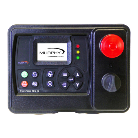
Murphy PowerCore TEC-10 User manual

Murphy

Murphy PowerCore TEC-10 User manual

Murphy Engine Throttle Controller AT-04060N User manual

Murphy

Murphy Engine Throttle Controller AT-04060N User manual

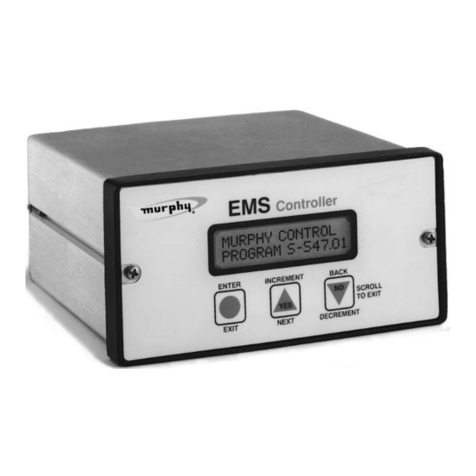
Murphy EMS447 User manual

Murphy

Murphy EMS447 User manual

Murphy EMS PRO User manual

Murphy

Murphy EMS PRO User manual

Murphy Automatic Engine Controller A88 User manual

Murphy

Murphy Automatic Engine Controller A88 User manual

Murphy Cascade CD101 User manual

Murphy

Murphy Cascade CD101 User manual

Murphy Automatic Engine Controller AS3000 User manual

Murphy

Murphy Automatic Engine Controller AS3000 User manual

Murphy Autostart AS731 User manual

Murphy

Murphy Autostart AS731 User manual

Murphy Autostart 730 AS730 User manual

Murphy

Murphy Autostart 730 AS730 User manual

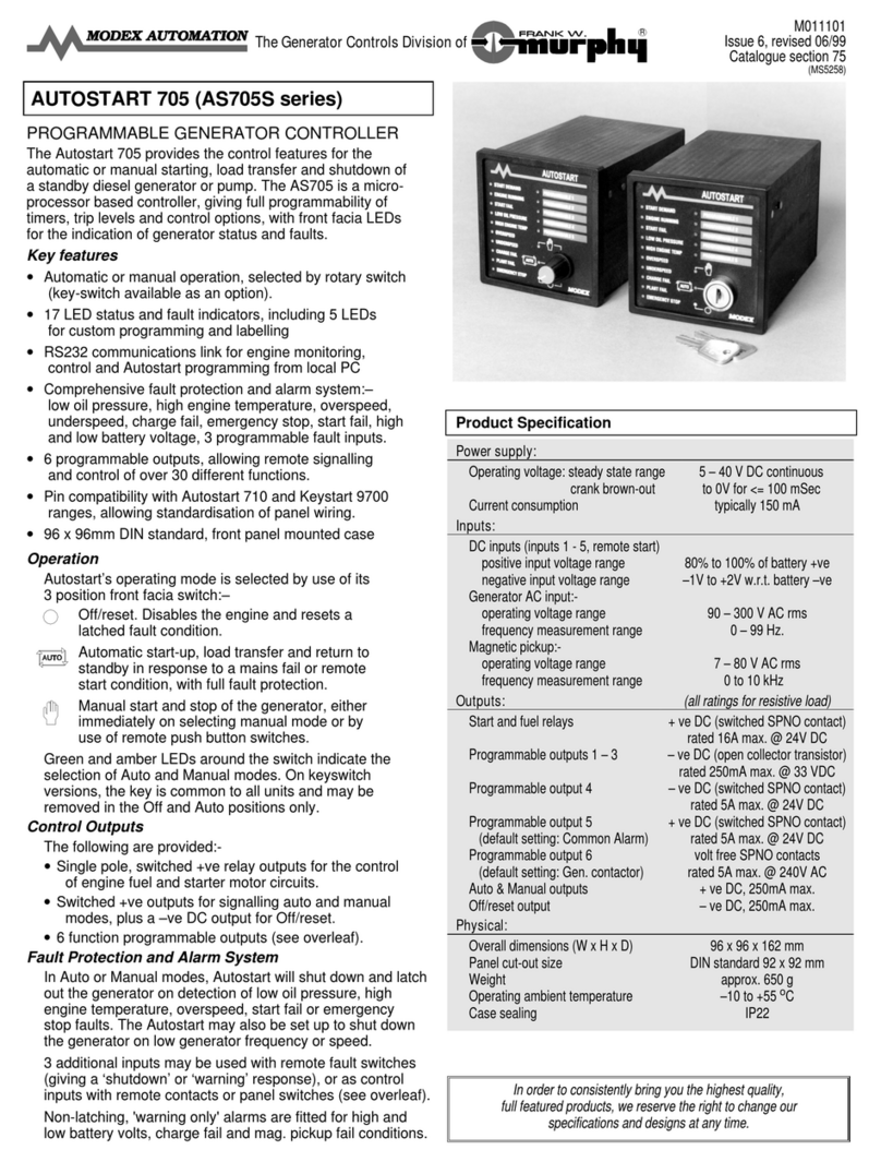
Murphy Autostart 705 AS705S User manual

Murphy

Murphy Autostart 705 AS705S User manual

Murphy Centurion Configurable Controller CE-05171N User manual

Murphy

Murphy Centurion Configurable Controller CE-05171N User manual

Murphy Glow Plug Control Module GPM92 User manual

Murphy

Murphy Glow Plug Control Module GPM92 User manual

Murphy CONNECT User manual

Murphy

Murphy CONNECT User manual

Murphy Automatic Engine Controller EA150 User manual

Murphy

Murphy Automatic Engine Controller EA150 User manual

Murphy Autostart 710 AS710S User manual

Murphy

Murphy Autostart 710 AS710S User manual

Murphy LR579 User manual

Murphy

Murphy LR579 User manual

Murphy LR857 User manual

Murphy

Murphy LR857 User manual

Murphy Engine Throttle Controller AT-67207 User manual

Murphy

Murphy Engine Throttle Controller AT-67207 User manual

Murphy Engine and Generator Controls Keystart 9620 User manual

Murphy

Murphy Engine and Generator Controls Keystart 9620 User manual

Murphy EMS547 User manual

Murphy

Murphy EMS547 User manual

Murphy iGUARD AL-02058B User manual

Murphy

Murphy iGUARD AL-02058B User manual

Murphy Selectronic Micro-Controller Series 1500 User manual

Murphy

Murphy Selectronic Micro-Controller Series 1500 User manual

Murphy PowerCore MGC1000 User manual

Murphy

Murphy PowerCore MGC1000 User manual

Popular Controllers manuals by other brands

Meridian 861V4 Service guide

Meridian

Meridian 861V4 Service guide

ETC P-ACP Configuration manual

ETC

ETC P-ACP Configuration manual

FUJI CONTROLS CP-2 instruction manual

FUJI CONTROLS

FUJI CONTROLS CP-2 instruction manual

Rotex Controller Series Product documentation

Rotex

Rotex Controller Series Product documentation

Timpex REG110 user manual

Timpex

Timpex REG110 user manual

Epson RC520 manual

Epson

Epson RC520 manual

Brooks 609638 quick start guide

Brooks

Brooks 609638 quick start guide

Titan Controls Helios 3 instruction manual

Titan Controls

Titan Controls Helios 3 instruction manual

Allen-Bradley SoftLogix 5800 user manual

Allen-Bradley

Allen-Bradley SoftLogix 5800 user manual

DriSteem Vapor-logic 4 Installation and operation manual

DriSteem

DriSteem Vapor-logic 4 Installation and operation manual

Geco GH10HA user manual

Geco

Geco GH10HA user manual

LS XBF-LD02S installation guide

LS

LS XBF-LD02S installation guide

HORA MC250/24 operating manual

HORA

HORA MC250/24 operating manual

Regin AQM2000A-1R manual

Regin

Regin AQM2000A-1R manual

Renkforce LEDmaster-II operating instructions

Renkforce

Renkforce LEDmaster-II operating instructions

NXP Semiconductors MC9328MX1 Setup and use

NXP Semiconductors

NXP Semiconductors MC9328MX1 Setup and use

LOVATO ELECTRIC ATL600 instruction manual

LOVATO ELECTRIC

LOVATO ELECTRIC ATL600 instruction manual

Embedded Artists LPCXpresso user guide

Embedded Artists

Embedded Artists LPCXpresso user guide

manuals.online logo
manuals.online logoBrands
  • About & Mission
  • Contact us
  • Privacy Policy
  • Terms and Conditions

Copyright 2025 Manuals.Online. All Rights Reserved.