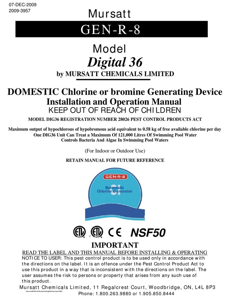
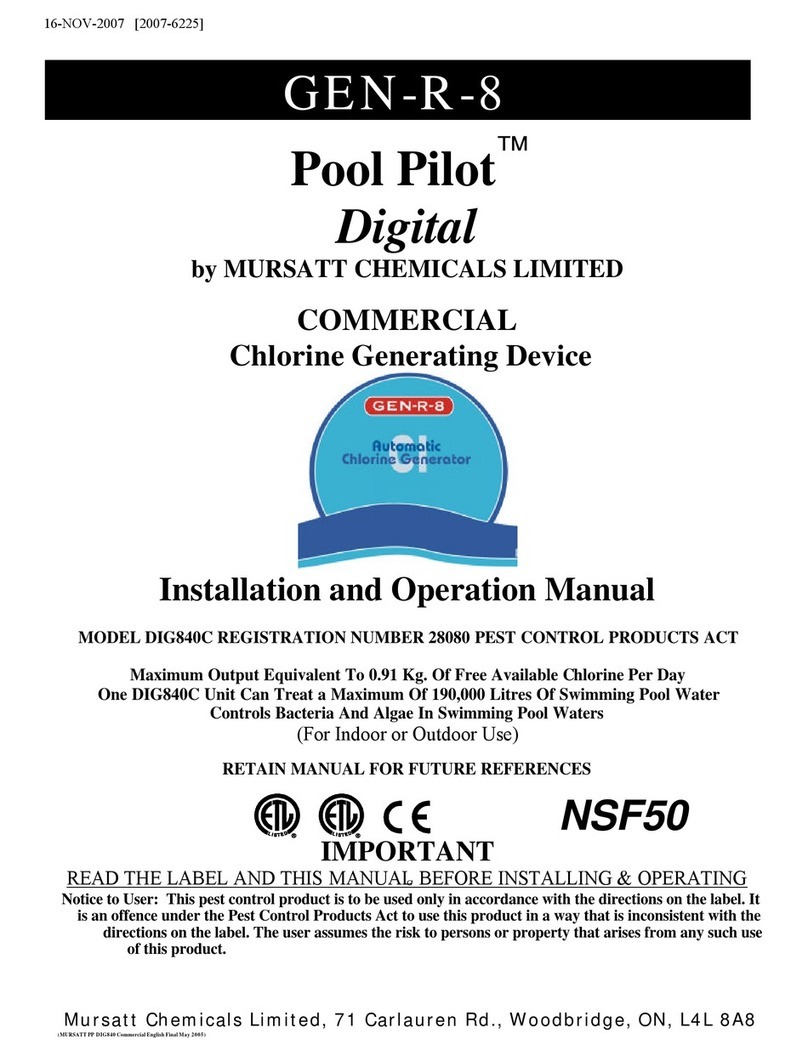
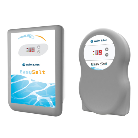
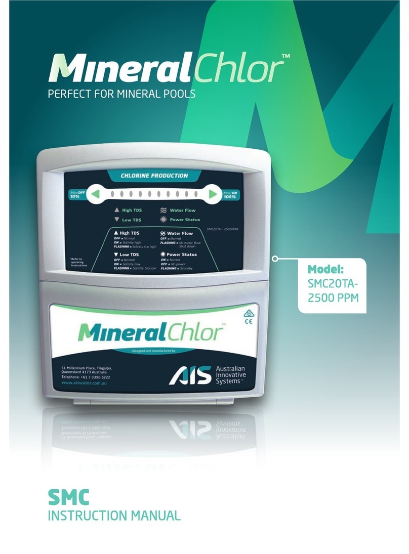
MURSATT CUBBY GEN-R-8 User manual

By MURSATT CHEMICALS LIMITED
DOMESTIC
Installation / Operation Manual
MODEL AC5 REGISTRATION NUMBER 28079 PEST CONTROL PRODUCTS ACT
PLEASE RETAIN OWNER'S MANUAL FOR FUTURE REFERENCE
IMPORTANT
READ THE LABEL AND THIS MANUAL BEFORE INSTALLING & OPERATING
Mursatt Chemicals Limited, 71 Carlauren Rd., Woodbridge, ON, L4L 8A8
CUBBY
PURIFICATION SYSTEMS
GEN-R-8
C
Mursatt CUBBY English Manual Nov 2004TEMP 2
MODEL AC3 REGISTRATION NUMBER 28022 PEST CONTROL PRODUCTS ACT
20-Oct-2008
2008-3530

TABLE OF CONTENTS
Models: AC3 & AC5
Important Safety Instructions
i,ii
Health, General & Hyperthermia 1
Specifications 2
Section 1 Water Pretest & Preparation
1 a
System Sizing 3,4
1 b
Pool Water Preparation & Monitoring 5-6
Section 2 Plumbing Requirements
2a Material Requirements for Installation 7
2b Cell Installation & Pool Diagrams 8, 9
Section 3 Control Panel Mounting & Wiring
3a Wiring 10
3b General Information 11
Section 4 Start Up & Operation
4a Control Panel Indicators 12,13
4b
Start Up Sequence
13
Section 5 Trouble Shooting
5a Trouble Shooting 14,15
Appendix
Appendix -Above Ground Installation Locations 16,17,18
Appendix -Service Information 19

IMPORTANT SAFETY INSTRUCTIONS
READ AND FOLLOW ALL INSTRUCTIONS
EQUIPMENT RELATED, INSTALLATION AND GENERAL USE
Installation of all GEN-R-8Purification Systems CUBBY models
When installing and using the GEN-R-8 Purification Systems CUBBY unit, basic safety
precautions must always be followed, including the following:
1. Follow all aspects of the local and National Electrical Code(s) when installing the GEN-R-8
Purification Systems CUBBY unit.
2. During installation, mount the
CUBBY
unit to ensure the least amount of direct exposure to
rain, garden sprinkler water, direct sunlight or any corrosive environment.
3. WARNING
-
Risk of electrical shock. Install at least 1.5 m (5 feet) from the insi
de wall of the
pool or spa using non-metallic plumbing.
4. WARNING
-
Do not use spas, hot tubs or pools unless all suction grates are installed to pre
-
vent body and hair entrapment.
5. DANGER
-
To reduce the risk of drowning from hair and body entrapment,
install suction fit
-
ting(s) with a marked flow rate that equals or exceeds the flow rate on the equipment
assembly.
6. WARNING -Install blower no less than 30 cm (1 foot) above the maximum water level to pre-
vent water from contacting electrical equipment.
7. Do not install the CUBBY unit within an outer enclosure or beneath the skirt of a hot
tub or spa.
8. CAUTION -Maintain water chemistry in accordance with manufacturer's instructions.
9. All field
-
installed metal componen
ts such as rails, ladders, drains, or other similar hardware
within 3 m (10 feet) of the spa or hot tub shall be bonded to the equipment grounding bus
with copper conductors not smaller than No. 8 AWG in the U.S.A. and No. 6 AWG in Canada.
i

110V Models Only (cord and plug)
1. WARNING
-
Risk of Electric Shock. Connect only to a grounding type receptacle protected by
a ground-fault-circuit-interrupter (GFCI). Contact a qualified electrician if you cannot veri-
fy that the receptacle is protected by a GFCI. The conductors on the load side of the GFCI
shall not occupy conduit boxes or enclosures containing other conductors unless the
additional conductors are also protected by a GFCI.
2. The GFCI must be tested before each use. With the
CUBBY
unit operating pus
h the test but
-
ton on the GFCI. The CUBBY unit should stop operating. Push the reset button. The CUBBY
unit should now start to operate normally. If the GFCI fails to operate in this manner,
there is a ground current flowing indicating the possibility of an electrical shock.
Disconnect the power until the fault has been identified and corrected.
3. WARNING -To reduce the risk of electric shock, replace damaged cords immediately.
4. WARNING
-
To reduce the risk of electric shock, do not use extension cords to
connect unit
to electric supply; provide a properly located outlet.
5. Do not bury cord. Locate cord to minimize abuse from lawn mowers, hedge trimmers and
other equipment.
220V Models Only (fixed wiring)
1.
A wire connector is provided on the
CUBBY
unit
to connect a minimum No. 8 AWG (8.4mm)
solid copper conductor between this unit and any metal equipment, metal enclosures of
electrical equipment, metal water pipe, or conduit within 1.5 m (5 feet) of the unit.
2. A bonding terminal is located inside the
CUBBY
unit. To reduce the risk of electrical shock,
this terminal must be connected to the grounding means provided in the electric supply
service panel with a continuous copper wire equivalent in size to the circuit conductors
supplying the CUBBY.
General Use
1. WARNING
-
To reduce the risk of injury do not permit children to use this product unless
they are closely supervised at all times. Children should not use spas, hot tubs or pools
without permanent adult supervision.
2. WARNING
-
Risk of Accidenta
l Drowning. Extreme caution must be exercised to prevent
unauthorized access by children. To avoid accidents, ensure that children cannot use a spa,
hot tub or pool unless they are closely supervised at all times.
3. DANGER
-
To reduce the risk of injury,
do not remove the suction grates. Never operate a
spa or pool if the suction grates are broken or missing. Never replace a suction grate with
one rated less than the flow rate marked on the equipment assembly.
4. DANGER
-
Risk of electrical shock. Do not p
ermit any electrical appliance, such as a light,
telephone, radio, or television, within 1.5m (5 feet) of spa or pool.
5. To avoid injury exercise care when entering or exiting the spa, hot tub or pool.
IMPORTANT SAFETY INSTRUCTIONS
ii

HEALTH, GENERAL
AND HYPERTHERMIA
General: WARNINGS -To reduce the risk of injury:
1. People using medications and/or having an adverse medical history should consult a physician
before using a spa, hot tub or pool.
2. People with infectious diseases should not use a spa, hot tub or pool.
3. The water in the spa should never exceed 40°C (104°F). Water temperatures between 38°C
(100°F) and 40°C (104°F) are considered safe for a healthy adult. Lower water temperatures
are recommended for young children and when spa use exceeds 10 minutes.
4. Water temperature in excess of 38°C (100°F) may be dangerous to your health.
5. Pregnant or possibly pregnant women should consult a physician before using a spa or hot
tub.
6. Since excessive water temperatures have a hig
h potential for causing fetal damage during the
1st trimester of pregnancy, pregnant or possibly pregnant women should limit the spa water
temperatures to 38°C (100°F).
7. Before entering a spa or hot tub, the user should measure the water temperature with an
accurate thermometer since the tolerance of water temperature regulating devices varies.
8. The use of alcohol, drugs, or medication before or during spa or hot tub use may lead to
unconsciousness with the possibility of drowning.
9. Obese persons and persons with a history of heart disease, low or high blood pressure, circu-
latory system problems, or diabetes should consult a physician before using a spa.
10.
Persons using medication should consult a physician before using a spa or
hot tub since
some medication may induce drowsiness while other medication may affect heart rate,
blood pressure, and circulation.
11. Do not use a spa or hot tub immediately following strenuous exercise.
12. Prolonged immersion in a spa or hot tub may be dangerous to your health.
Hyperthermia
WARNING -The use of alcohol or drugs can greatly increase the risk of fatal hyperthermia in hot
tubs and spas.
Consult your spa/hot tub manufacturer's manuals for the proper adjustment of wat
er tempera
-
ture. Prolonged immersion in hot water may induce hyperthermia. Hyperthermia occurs when
the internal temperature of the body reaches several degrees above the normal body
temperature of 37°C (98.6°F). Hyperthermia symptoms include drowsiness, lethargy, and
an increase of internal body temperature.
The effects of hyperthermia include:
1. unawareness of impending hazard
2. failure to perceive heat
3. failure to perceive the need to exit the spa/hot tub
4. physical inability to exit spa
5. fetal damage in pregnant women
6. unconsciousness and danger of drowning
SAVE THESE INSTRUCTIONS
HEALTH, GENERAL & HYPERTHERMIA
1

Specifications
Outputs
Model AC3 Cell Maximum output of Sodium Hypochlorite equivalent to 0.11 kg. of chlorine @3.0
Amps per 24 hours @ma x. dial setting of 100%
Model AC5 Cell Maximum output of Sodium Hypochlorite equivalent to 0.22 kg. of chlorine @3.0
Amps per 24 hours @max. dial setting of 100%
Flow Rate
Minimum: 57 Litres per minute.
Maximum: 189 Litres per minute. (USE EXTERNAL BYPASS IF
FLOW RATE EXCEEDS 189 L.P.M.)
Specifications
Reverse Polarity Function (Standard in all models)
The Reverse Polarity Function is designed to automatically clean the cell blades, maximizing the
cell's ability to manufacture chlorine or bromine.
This feature is only enabled when the GREEN OK indicator is flashing. Since the OUTPUT
CONTROL DIAL affects the amount of time the GREEN OK indicator is flashing, it also has the
same effect with regards to the Reverse Polarity Function. See table below.
OUTPUT DIAL TIME
0
DOES NOT
REVERSE
25% Every 15 hrs.
50% Every 12 hrs.
75%
Every
9 hrs.
100% Every 6 hrs.
ALL MODELS INPUT: 105 –125 VAC, 50/60 HZ, 1.0 Amp for Model AC3-1 or AC5-1
210 –250 VAC, 50/60 HZ, 0.5 Amps for Model AC3-2 or AC5-2
Automatic Self Cleaning Feature
2

System Sizing for Swimming Pools
System Sizing
Use these three formulas to calculate the volume of water in the pool/spa:
Rectangular Pool: Length(M) x Width(M) x Average Depth(M) x1000 = Total Litres
Oval / Round Pool: Diameter (M) x Diameter (M) x Average Depth (M) x 790 = Total Litres
Free Form Pool: Average Length (M) x Average Width (M) x Average Depth (M) x 1000 = Total Litres
CUBBY System Production Capacity
IMPORTANT CONCEPTS
1 . Purifier Demand / Pool Requirements
The rate at which purifier is consumed in any swimming pool depends on the relationship of eight major
variables. Since these variables can vary widely from pool to pool and season to season, precise prediction of
the purifier demand for any one pool is difficult. At the end of this section, rules of thumb are provided for
CUBBY System Sizing.
THE VARIABLES ARE:
1. Volume and surface area of the pool /spa being purified.
2. Average water temperature maintained: As the temperature of the water increases, the purifier demand
will also increase. As the temperature of the water decreases, the purifier demand will also decrease.
When this happens, the output dial should be decreased to compensate for this lower demand (which
will also protect your equipment from excessive levels of purifiers).
3. Cyanuric acid level maintained: This chemical, when added to pool water, significantly inhibits purifier
depletion from exposure to sunlight. Cyanuric acid also inhibits corrosion if your pool is equipped with any
metal components. Minimum levels or better must be maintained to ensure that the purifier being
produced is protected from UV breakdown.
4. Bather load: As the bather load increases, the purifier demand will also increase.
5. Amount of direct sunlight / UV exposure: Pools exposed to larger amounts of direct sunlight are more
vulnerable to increased purifier loss and algae growth. Indoor or screened pools have less purifier
demand.
6. Exposure to vegetation and airborne debris: Dense landscaping near the pool, along with increased
nitrate levels (urine, bird droppings, fertilizer, well water, etc.) greatly contribute to increased purifier
demand.
7. Chemical dilution: Virtually all pool chemicals experience dilution through rainfall and the adding of
fresh make-up water (due to evaporation, splash-out, filter backwashing, leaks, etc). When
freshwater is added, purifier demand increases for a brief period.
8. Main filter pump runtime and your pool's circulation patterns: Purifier can only be produced while the
main filter pump is operating. Waterfalls/Fountains and other water features operated by the filter pump
can directly effect purifier demand. The main filter pump runtime and/or output dial may need to be
increased to satisfy this higher demand.
Section 1 a
3

2. Purifier Production/ System Sizing/ "Rules of Thumb"
While purifier demand varies beyond precise prediction, and you may desire a higher or lower
purifier residual in your pool, the following "rules of thumb" will assist you in properly selecting
the correct Gen-R-8 Purification Systems CUBBY model.
1. A Control Panel with a Gen-R-8 Purification Systems CUBBY Model AC3 cell , operated at
maximum output (3.0 Amps), at 3000 ppm salt residual will produce Sodium Hypochlorite
equivalent to 0.11 kg of chlorine in 24 hours of continuous operation.
This amount of chlorine could satisfy up to 37,000 L of pool water, depending on the 8
demand variables for purifier.
2. A Control Panel with a Gen-R-8 Purification Systems CUBBY Model AC5 cell , operated at
maximum output (3.0 Amps), at 3000 ppm salt residual will produce Sodium Hypochlorite
equivalent to 0.22 kg of chlorine in 24 hours of continuous operation.
This amount of chlorine could satisfy up to 57,000 L of pool water, depending on the 8
demand variables for purifier.
NOTE: Residual salt levels must be maintained above 2800 ppm and below 3200 ppm. Do not
exceed 3200 ppm salt residual if you object to salty tasting water!
Normal System Sizing Guide
The sizing criteria below reflects "normal"conditions based on field experience and proper
operation. Purifying "demand" varies from one pool to another.
Percent of
Purifier Provided
100%
75%
50%
25%
AC3 CELL AC5 CELL
Litres 18,500 37,000 57,000
POOL SIZE
Assumes "Normal" Demand @ 10 Hours Per Day Operation
System Sizing for Swimming Pools (Continued) Section 1 a
4

STEP 1 -Proper Water Balance Requirements:
Proper CUBBY System operation is dependent on proper pool water conditions. Manually balance the pool
water chemistry to meet all suggested ranges of water balance factors listed below before start-up of the
CUBBY unit. From that point forward your CUBBY System will assist you in keeping your water chemistry
factors in balance.
BEFORE START UP, MAKE SURE THE POOL WATER MEETS THE FOLLOWING REQUIREMENTS: ALL WATER
BALANCE FACTORS SHOULD BALANCE WITH LANGELIER'S SATURATION INDEX. WE RECOMMEND A VISIT
TO YOUR LOCAL POOL PROFESSIONAL.
CUBBY System Required Ranges (And periods for testing water for these water balance factors.)
STEP 2 -Bi-Weekly Checks 3) Calcium Hardness 200 -300 ppm
1) Free Available Chlorine = 1.0 -3.0 ppm (pool)
4) Total Alkalinity 100 -200 ppm
Free Available Bromine = 2.0 -4.0 ppm (pool)
5) Cyanuric Acid 60-80 ppm (Outdoor)
Free Available Chlorine = 3.0 -5.0 ppm (spa)
6) Salt Residual 2800-3200 ppm
Free Available Bromine = 3.0 -5.0 ppm (spa)
7) Langelier's Index (water balance) + or -0.3
2) pH 7.2-7.8
STEP 3 -Monthly Checks: CAUTION: Excessive Free Available Chlorine(>3.0 ppm) or Free Available
Bromine (> 4.0 ppm) causes corrosion of any metal components in contact with pool/spa water. Staining
and premature failure of heaters, filters, and other metal components will be the result. Do not exceed
recommended purifier ranges. NOTE: Standard (DPD) pool water test kits do not read chlorine/bromine
levels above approximately 8.0 ppm. Test reagents, at high levels, return to a clear liquid. AVOID HIGH
PURIFIER LEVELS!
STEP 4 -Salt Requirements: It is important that a suggested salt level of 3000 ppm be maintained at all
times. Allowing less than 2800 ppm salt will activate a double flashing red CHECK SYSTEM light and stop
purifier generation. The amount of salt required depends on the size of the pool. Use the chart on the next
page to determine the amount of salt to add, in pounds or kilograms, for a new pool start up. Also test
your make up water for its level of salt and compare it with the charts on the next page. Before adding
salt to a pool for the first time, turn your CUBBY unit OFF, open your main drain, then pour salt around
the perimeter of the pool.
NOTE: Homeowners with water softening/treatment equipment, which utilize salt, may already have sub-
stantial levels of salt in their drinking water. So before adding this water to your pool, test the level of
salt, then determine the amount of salt still needed to be added to bring the level up to the suggested
3000 ppm start-up level.
NOTE: Before adding any make-up water to your pool, it is suggested that pretesting the make-up water
for high pH, total alkalinity and calcium hardness will aid in the adjustment of these levels before they
become excessive.
Manual Cleaning Of Cells
In normal conditions the CUBBY unit should not require Manual Cleaning. If manual cleaning is required,
check water chemistry for possible imbalances or call the factory for consultation, and use the following
procedure:
STEP 1 -Remove the cell by loosening the unions to release.
STEP 2 -Fill a bucket with 1 part muriatic acid added to 4 parts of water. PUT WATER IN BUCKET FIRST!
CAUTION: Always add acid to WATER,never water to acid.
STEP 3 -Submerge the cell, NOT THE FLOW SWITCH!
STEP 4 -After 10 -15 minutes of foaming, remove the cell. Rinse out with fresh water.
STEP 5 -If cell blades still have white crusty scale deposits on them, repeat the process, not to exceed 15
minute intervals.
NOTE: DO NOT try to remove any scale from cell blades with any tools. This may scratch or damage
the coating on the blades and will VOID WARRANTY.
Pool Water Preparation & Monitoring
Section 1 b
5

KILOGRAMS OF SALT NEEDED FOR 3000 PPM RESIDUAL
Salt Level Pool / Spa Volume in 1000’s of Litres
Before
Addition 123.5
715
30 35 43 50 57
0 ppm 2.5 510 21 42 85 106 127 148 170
320 ppm 2.2 4.5
918 38 76 94 113 132 152
640 ppm 24816 33 67 83 100 116 134
960 ppm 1.5 3714 28 58 72 86 101 116
1280 ppm 1.3 2.7
612 24 48 60 72 85 97
1600 ppm 1.1 2.2
4.5 919 39 49 59 69 79
1920 ppm 0.9 1.8
3.6 715 30 38 45 53 61
2240 ppm 0.4 0.9
2.2 510 21 26 32 37 43
2560 ppm 0.3 0.6
1.3 2.7 612 15 18 21 25
2880 ppm 0.08
0.1 0.3 0.6 1344.5 57
Cyanuric Acid / Stabilizer/Conditioner
Cyanuric acid, CYA, (also known as stabilizer orconditioner) prevents rapid breakdown of chlorine by
sunlight and inhibits the corrosive effects of chlorine and bromine. Regulations may exist regarding use of
Cyanuric acid in public pools; please consult your pool professional. Use the chart below to determine the
amount of Cyanuric acid needed. Test water with a test kit that includes CYA testing, then use the chart
below to determine the amount to add.
KILOGRAMS OF CYANURIC ACID NEEDED FOR 75 PPM RESIDUAL
CYA Level Pool / Spa Volume In 1000's of Litres
Before
Addition 12.5 510 15 20 30 40 57
0 ppm 0.08 0.17 0.34 0.68 11.3 22.7 4
12 ppm 0.07 0.14 0.28 0.56 0.85 1.1 1.7 2.2 3.4
25 ppm 0.05 0.11 0.22 0.45 0.68 0.9 1.3 1.8 2.7
37 ppm 0.04 0.08 0.17 0.34 0.51 0.68 11.3 2
50 ppm 0.02 0.05 0.11 0.22 0.34 0.45 0.68 0.9 1.3
62 ppm 0.01 0.02 0.05 0.11 0.17 0.22 0.34 0.45 0.68
Salt Requirements Needed for 3000 PPM
Cyanuric Acid Needed for 75 PPM
Section 1 b
Section 1 b
6

NEEDED BY INSTALLER SUPPLIED WITH CUBBY UNIT
1)
Required amount of salt
1)
Residential Installation /Operation
2)
Hacksaw, Pipe Cutters or Cable Saw
Manual
3)
Tape measure & Permanent Marker 2)
Limited Warranty with Warranty
Card (Must Return)
4)
Screwdrivers: Flat head & Phillips 3)
CUBBY Control Panel
head
4) · Chlorine/Bromine Production Cell
5)
Pair of medium size needle nose · Flow Detector With Tee
pliers (For removal of the Output (Where applicable)
Control Dial) · Cell Unions
(
Where applicable)
6)
Drill with 6mm (1/4") masonry-drill
bit for block or stucco
5)
Salt test strips & vial.
7)
Voltmeter -To determine AC voltage
to Control Panel
6)
Installation kit,
8)
Test kit for Chlorine/Bromine, Including mounting hardware.
Calcium Hardness, pH, Total
Alkalinity, and Cyanuric Acid
(stabilizer).
9)
P.V.C. Glue
10)
P.V.C. Cleaner / Primer
11)
Assorted P.V.C. Fittings & Pipe
(Hose couplings & clamps for
above ground pool projects)
12)
Assorted Electrical Hookup
Components
13)
Teflon tape or pipe joint compound
14)
Large Channel Lock Pliers
Material Requirements for Installation Section 2 a
7

Control Panel
Using the supplied anchors and screws, the Control Panel should be mounted on a flat, sturdy,
vertical surface away from direct exposure to sunlight. The Control Panel is equipped with a 3.65 m
DC cell cord and flow detector cord. For ease of installation, please ensure that both cords connect
to the cell and flow detector while still providing slack in each cord for future service. Using a
torpedo level and permanent marker, hold and level the Control Panel on the surface to be mounted
and dot each of the (4) mounting holes. Using a .63 cm drill bit, drill to a depth of 2.5 cm and install
the supplied anchors. The Control Panel is now ready to receive the (4) mounting screws to secure
the installation.
DO NOT SHOOT OR PERMANENTLY ATTACH THE CONTROL PANEL TO THE WALL! This will void the
WARRANTY.
NOTE: Install at least 1.53m from the
inside wall of the pool or spa.
CAUTION -YOU MUST REMOVE THE OUTPUT CONTROL DIAL BEFORE ATTEMPTING TO REMOVE
THE COVER. FIRST PRY OFF THE CAP AT THE TOP OF THE KNOB, WHICH WILL REVEAL THE HEX
NUT. LOOSEN THE NUT AND LIFT OFF THE KNOB.
Typical In
-
Line Equ
ipment Power
Connection (220V)
NOTE 1 : FOR 24 HOUR OPERATION AS A "CONVECTION STYLE" INSTALLATION, SEE APPENDIX
(PAGE 18)
NOTE 2: IF YOU NEED A TIME CLOCK FOR CONTROL OF THIS UNIT AND YOUR 110 VOLT POOL
PUMP (PLUG IN), ASK ABOUT OUR PORTABLE TIME CLOCK .
Control Panel & Cell Installation
Section 2 b
8
CUBBY
Output Control
Required Salt Level
2500 -3500
Flashing Green Light –
Generating Purifier
Flashing Red Light
–Check System
External
Filter
Pump
Control
System
LOADSID
E AC POWER
FROM EXTERNAL
FILTER PUMP
CONTROL SYSTEM
TO
POOL
PUMP
F
I
L
T
E
R
HEATER
¶ 
¶ 
SINGLE GANG
JUNCTION
BOX (WIRENUT
CONNECTIONS)
POWER SUPPLY
FLOW DECTECTOR CORD
FLOW DETECTOR
DC CELL CORD
CELL
CELL UNION (TYP.)
FROM
POOL
OPTIONAL 2 LB / 13.8 kPa CHECK VALVE (FOR HIGH
FLOW CONDITIONS OVER 50 GPM / 189 LPM).

NOTE: See diagrams below for the proper location of the flow detector and cell, so not to over
chlorinate/brominate the spa.
Pool/Spa
Pump
Three Way
(Motorized) Valve
Flow
Single Pump Pool /Spa Combination
NOTE: If this scheme is desired and the spa is raised, a Swing Check Valve must be installed after the
three way Return (Motorized) Valve on the Spa Jet line to ensure spa drain down does not occur.
Swing Check Valve
Optional 2 Way
Valves For Spa
Draining &
Service
Flow
Dual Pump Pool /Spa Combination
NOTE: If this scheme is desired and the spa is raised, a 5 LB / 34.5 kPa Check Valve must be installed
on the Pool Return line before the flow detector to ensure adequate spa spillover.
Install Flow
Detector (s) &
Cell Here
In-Line Cell Installation Locations Section 2 b
Install Flow
Detector(s)
& Cell Here
9

220V MODELS ONLY (You cannot switch to 110 volt power)
STEP 1 -Wiring
All electrical equipment must be located 1.50 m or more from closest pool or spa waterline. Use the
green and yellow stranded wire for Control Panel grounding. Attach a #8 or #6 solid bond wire to
the bonding lug on the underside of the unit.
STEP 2 -Wire from the sub-panel -Your CUBBY Control Panel is shipped factory set to 220 VAC
ONLY. The Control Panel will operate at either 50Hz or 60Hz line power. Ensure that the filter pump
AC voltage used matches the Control Panel voltage. Improper wiring will damage the Control
Panel, which is not covered under warranty. Connect AC power to the blue and brown wires using
wire nuts.
STEP 2 a -Control Panel Hook-up -Ensure that the main filter pump circuit breaker is set to OFF.
Connect AC from the LOAD SIDE of the external time clock, Compool/Jandy filter pump relay or
on/off switch to the CUBBY Control Panel so that it operates only while the filter pump operates.
For flexibility, ease of wiring and making connections, #14 gauge stranded wire (2.1m) is
recommended for interconnection between the external control system and the Control Panel.
Wiring diagrams are located on the Control Panel's backplate. Plug the cell and flow switch cords
into the bottom of the unit.
110V MODELS ONLY (You cannot switch to 220 volt power)
STEP 1 -Plug the CUBBY unit into a G.F.C.I. (Ground Fault Circuit Interrupter) protected
outlet or timer.
STEP 2
-
Plug the 110V filter pump into the CUBBY unit AC outlet.
WARNING
-
This AC outlet is intended ONLY for the filter pump. DO NOT use for a
ny other purpose.
Each CUBBY Automatic Sanitizing System consists of three (3) main components:
The CONTROL PANEL converts incoming AC power to a Low Voltage DC current which energizes
the Cell.
The CELL receives that Low Voltage DC current from the Control Panel, indicated by a flashing
green OK indicator, which initiates the electrolytic process and allows purifier to be produced.
This process converts salt (Sodium Chloride) to Sodium Hypochlorite which in turn purifies
your pool. This salt then reverts back to ordinary salt and the entire process is repeated.
The FLOW DETECTOR ensures adequate flow is present to produce purifier. Further, it protects
the Cell from damage caused by insufficient flow. If the flow rate drops below 57 LPM, the
Control Panel will display a single red flashing CHECK SYSTEM indicator and the OK indicator will
display dark.
BOTH MODELS
STEP 1 -Plug the cell cable into the cell and the other end into the 3 circuit connector located at
the bottom right side of the CUBBY unit. It matches only one type connector, and it's keyed. You
can't make a mistake.
STEP 2 -Plug the flow switch cable into the WHITE 2-circuit connector closest to the wall at the
bottom of the CUBBY unit. This input connector is keyed. See drawing top left page 17.
Control Panel Wiring
3.
2.
1.
Section 3 a
10

a) ORP Controller -Install part # 993 per the instructions provided.
NOTE: This is a dry contact input, DO NOT ENERGIZE THIS INPUT! DAMAGE TO THE CONTROL
PANEL WILL OCCUR AND THE WARRANTY WILL BE VOIDED. When an ORP controller is
interfaced to the CUBBY unit, your Output Control Dial should be set on 100%.
b) Power Fuse -On the Control Panel circuit board is a 2 amp power fuse labeled FS1 for the
110V unit, and a 1 amp fuse for the 220V unit. This fuse protects the Control Panel and cell
from voltage spikes. If no lights display, inspection and possible replacement of this fuse may
be necessary. The output control dial and cover must be removed from the unit to access this
fuse.
UNION
CUBBY
CONTROL
PANEL
FLOW
DETECTOR
CORD
Required Salt Level
2800 -3200 ppm
CHECK MONTHLY
Electronic Component Location Models AC3 and AC5
Control Panel Models AC3 and AC5
CUBBY
Section 3 b
Section 3 b
11

Indicator Lights
A. WHEN POWER IS FIRST TURNED ON:
The lights will flash alternately for one minute while the CUBBY unit self-tests and awaits continuous flow.
B. OK:
If your CUBBY unit is wired properly, this indicator will display GREEN whenever the main filter pump is operating.
This indicator ensures that proper incoming AC power is being delivered to the Control Panel. Further, this indicator
will FLASH GREEN whenever the system is producing purifier, and display steady green when the cell is in rest mode.
C. CHECK SYSTEM:
This indicator will display dark (OFF) whenever the Control Panel is operating correctly. While this indicator displays
dark, rest assured that your pool is being purified by Hypochlorous Acid (from Sodium Hypochlorite) when the green
OK indicator is flashing. For further explanation of this indicator, please refer to the Trouble Shooting Guide beginning
on page 14.
Output Control
The Output Control Dial is a percentage timer that regulates the amount of time the system is to produce
chlorine/bromine during the filter pump running cycle. The output is regulated according to the setting of this dial.
Each setting has a memory cycle of 36 minutes. The setting of the dial will determine how long the cell will
produce chlorine/bromine and how long it will be in the rest mode. While in the rest mode your OK indicator will
display steady green to indicate that no chlorine/bromine is being produced but the power is on. Below is a chart
that indicates the on and off periods of each output setting.
NOTE: Any interruption of power, will cause the current memory cycle to reset itself when power is restored.
Dial Setting Approx. On-Time Approx. Rest-Time
00 min. 36 min.
50% 18 min. 18 min.
100% 36 min. 0 min.
CUBBY Control Panel Functions
Section 4 a
12

Use Of Sodium Bromide Once a bromine pool -Always a bromine pool.
SODIUM BROMIDE (OPTIONAL) -100 PPM
Where Cyanuric acid is not available or where its use is restricted, bromine can be used as an alternative purifier to
chlorine.
The CUBBY unit will convert sodium bromide to bromine in the same way that it converts sodium chloride to chlorine.
NOTE: Bromine pools do not require the addition of Cyanuric acid. Typical chlorine stabilizer provides no U.V. protection for
bromine residuals. DO NOT MAINTAIN OR ADD CYANURIC ACID TO A BROMINE POOL!
To produce hypobromous acid (bromine purifier), we recommend initially adding 10.9 kg of sodium bromide for every
45,000 Litres of pool water capacity. To maintain the sodium bromide level add 1.8 kg of sodium bromide for every 22.5 kg
of sodium chloride (salt) added to the pool.
REMEMBER: For the CUBBY System to operate properly, the pool water must contain the recommended level of both salts
as previously specified. (When used, sodium bromide is added in addition to the normal amount of sodium chloride
required.)
Before operating the CUBBY System, perform the following steps to ensure proper installation and operation:
A. Turn ON all circuit breakers to the pool equipment.
B. Set the output control dial at 50%.
C. Switch on the main filter pump, the following indicators should display .... a cycling green OK and red CHECK SYSTEM.
This is normal and will last 1 minute. After sufficient flow is detected, greater than 56LPM, the green OK indicator should
flash. If this sequence does not occur or any red indicators display, please refer to the Trouble Shooting Guide starting on
page 14 for further assistance.
NOTE: Be sure to test the chlorine/bromine level for the next few days and properly adjust the chlorine/bromine output
dial. DO NOT EXCEED RECOMMENDED CHLORINE OR BROMINE LEVELS!
As adjustments are required, make the adjustment and allow the pool to react to this change a minimum of 3 days. After
the 3 days expire, retest the pool water and make any further adjustments if necessary. Typically, when an adjustment is
made, the amount of time the main filter pump operates does not change. A simple rule to follow....
As the water temperature decreases, the purifier demand also decreases.
Lower the Output Control Dial to satisfy this change in purifier demand until it's necessary to raise the residual level. When
the water temperature drops below 14°C, lower the Output Control Dial. In some cases, set it to the "0 (zero)" position. Do
not allow chlorine or bromine residual to drop below minimum level. Because the water temperature is cooler, the purifier
demand is lower, it is unnecessary to produce as much purifier as normally produced in warmer water. Further, this action
protects the Cell from possible damage caused by operating below 14°C.
As the water temperature increases, the purifier demand also increases.
Raise the Output Control Dial and/or increase the main filter pump runtime to satisfy this change in purifier demand.
CUBBY Control Panel Functions (Cont’d) Section 4 a
13

PROBLEM CAUSE
SOLUTION___________________________
1. Insufficient purifier production.
A. The test kit reagents or test strips are old or expired. A. Retest with new reagents or test strips.
D. Purifier loss due to intense sunlight exposure.
D. Check the stabilizer level and add cyanuric acid if needed. (Refer
to the Cyanuric Acid Needed for 75 PPM section, page 6.) If
on bromine, replenish bromine residual.
2. Scale build-up within the cell.
B. The unit is set too low in relation to an increased purifier demand
B. Turn up the output dial and/or increase the filter pump run
time.
C. The bath
er load has increased.
C. Set the output control dial to 100 % and allow the filter pump to
operate 24 hours (were applicable remove the "OFF" tripper from
the external time clock) to super-chlorinate / brominate the water.
E. The b
ody of water being purified leaks.
E. Repair the leak and rebalance the water being purified. (Refer to the
Pool Water Preparation section, page 5.)
G. Flow cable plugged into wrong input.
G. Unplug cable from front input and plug
into back
input closest to wall.
A. The water being purified contains high pH,
A. Calculate Langelier's Index to assure balanced water. (See page 5)
alkalinity and calcium hardness. Adjust the water chemistry and mix 1 partmuriatic acid to 4 parts water.
Pour this solution into the cell and allow it to clean the cell for no
longer than 15 minutes. Repeat if necessary. Drain and rinse with
fresh water and re-install. Dilute pool water with fresh water if
necessary.
3.DC plug and cell terminals burned.
A. The cell cord plug is not securely pushed onto the cell
A.
Ensure that the cell cord plug is pressed completely on the cell
terminals terminal
allowing moisture to seep into the plug. Check the cell terminals and clean with a dry cloth to remove all dirt and corrosion.
4. Premature cell failure. (Requires replacement cell. Normal cell life, if sized and operated correctly, is 3
-
5 years.)
B. Debris in Cell
B. Inspect cell
monthly and clean debris if
required.
A. Abnormally high cell usage due to an insufficient cyanuric acid level. A. Check the stabilizer level and add cyanuric acid if
needed. (Refer to the Cyanuric Acid Needed for 75PPM
section, page 6.)
5. White flakes in the water.
This occurs when excessive calcium hardness is present in the
Monitor the pH and adjust if necessary.
water being purified. This should cease aftera few days. (Refer to the Pool Water Preparation section, page 5.)
6. No OK light.
A. Incoming AC power for the main filter pump is not present.
A. Ensure that the main filter pump circuit breaker is set to
"ON".
B. Power fuse blown B. Remove the knoband cover, replace this fuse.
14
B. The unit is not reversing polarity
B. Confirm with a 504 or 957 cell tester that it is not reversing polarity.
Send the control panel back to the factory for service..
C. Possible cell failure.
C. Check with either a 504 or 957 cell tester. Replace
the cell if needed. Refer to #4 of this section.
F. Low salt
F. Check the residual salt level and add if necessary. (Refer to the Salt
Requirements Needed for 3000 PPM section, page 6)
B. The cell terminals lea
k. B. Shut off the main filter pump and patch the cell terminal(s) with epoxy putty
and leave the filter pump off for 24 hours.
C. Completely failed cell C. Replace the cell.

PROBLEM CAUSE SOLUTION___________________________
7. Single CHECK SYSTEM Flash
A. Water exiting the filter is being diverted away from the
inlet of the flow detector A. Increase the flow rate above 15 gallons (56 LPM) per minute to activate
the flow detector.
B. Check the condition of the filter. B. If the filter is dirty clean it.
C. Ensure that the flow detector is not installed opposite in C. Extract the flow detector & re -install if necessary.
relation to the actual water flow.
D. The flow detector may have failed.
D. Replace the flow detector.
8. Double CHECK SYSTEM Flash
A. The cell is scaled. A. See # 2.
B. The cell cord is disconnected from the cell.
B. Ensure that the cell cord is firmly pressed
onto the cell.
C. Low salt
C. Check the residual salt
level and adjust if necessary.
(Refer to the salt requirements needed for 3,000 ppm section, page 6).
D. The unit is not reversing polarity.
D. Send the Control Panel back to factory for
service.
E. Possible cell failure. E. Check with either a 504 or 957 cell tester. Replace
the cell if needed. Refer to #4 of this section.
F. Very cold pool water. F. Lower the output control dial setting, even to the "0"
position, and add a non-chlorine shock to the pool until the
water temperature increases above 60° F (14°C).
9. Triple CHECK SYSTEM flash
A. Low cell voltage.
A. Check with either a 504 or 957 cell tester. A possible cell short circuit may
exist. Replace the cell if needed. Refer to #4 of this section.
10. Quadruple CHECK SYSTEM flash
A. No cell voltage or current. A. Send the control panel back to the factory for service.
15

BOTTOM
PANEL OF THE CUBBY UNIT CUBBY UNIT PRINTED CIRCUIT BOARD
MODEFUNCTION LO FLOW /ORP FLOW J2
1In-line operation Not connected Main flow switch Open
22-speed pump Low flow switch Main flow switch Open
(Generates reduced purifier
when pump is at low speed)
3Partial convection Shorting plug Main flow switch Open
(Generates reduced purifier by
convection when pump is not running)
4Full convection Not connected Shorting plug Open
(Continuously produces full
purifier output by convection)
5ORP Controller Interface ORP relay contacts(N.O.) Main flow switch Linked
1. 2 SPEED PUMP SYSTEMS ON SPAS AND SMALLER POOLS
-Add Low Speed Flow Switch Assembly
Most 2-speed circulation systems for pools and spas operate at high speed when the project is being used,
and run at low speed when not in use. The demand for purifier may be many times greater when the project is
being used than when it is not. To avoid overdose, add a Low Flow Switch Assembly.
When the CELL FLOW switch closes, the CUBBY unit delivers purifier at the rate set by the output control
dial. If the CELL FLOW SWITCH opens, but the LO FLOW remains closed, purifier is generated at 12% of the
output if the control dial is set at maximum.
The cell flow switch operates at 15 gpm (56 LPM). If a secondary flow switch, operating at 5 gpm (19
LPM.), is connected to the LOW FLOW / ORP (BLUE) input, the CUBBY unit will reduce its purifier output when
the pump runs at low speed, a situation when the pool or spa is not normally in use. This mode of operation
prevents overdosing, yet provides a purifier boost when the pool or spa is in use or the filter pump is
operating in high speed mode.
2.
CONVECTION APPLICATIONS
-
See Configur
ations 1 & 2 on pages 17 & 18.
Many above-ground pools benefit from continuous purification at a reduced rate when the pump is not run-
ning. This is done by permanently shorting the LO FLOW connector contacts with the white shorting plug
connector supplied in the installation kit, yet continuing to use a flow switch for the MAIN FLOW input. This
generates purifier at the rate set by the output control while the pump is running. When the pump is off, the
CUBBY unit continuously generates purifier in convection mode at 12% of the
output if the control dial is set at maximum.
In above-ground pool installations where the pump and filter are below the water level, the CUBBY unit
may be operated in a convection mode. This requires the following:
1. The cell MUST be located immediately adjacent to the discharge outlet in a vertical position.
2.Unobstructed flow is required through the cell, whether the pump is operating or not. This can be
accomplished by the method shown on page 18, using a check valve bypass run between the suction port
and discharge outlet.
3-Please do not install any shutoff valves on the bypass run between the suction port and discharge outlet
or after the cell. Obstructing the flow at the bypass run or after the cell will cause damage.
SUMMARY OF CUBBY UNIT OPERATING
MODES
LOW FLOW/ORP (Blue)
CELL
MAIN FLOW (White)
16
This manual suits for next models
8
Table of contents
Other MURSATT Swimming Pool Filter manuals
Popular Swimming Pool Filter manuals by other brands

Majestic
Majestic UNO Instructions for use

Aquadistri
Aquadistri BlueMarine Internal Skimmer 120 instruction manual

Bestway
Bestway AQUAFEED owner's manual

Bestway
Bestway FlowClear owner's manual

ChlorKing
ChlorKing NEXGEN80 Installation, operation and maintenance manual

Autopilot
Autopilot ChlorSync troubleshooting guide

Oase
Oase SwimSkim operating instructions

Pool Technologie
Pool Technologie UNO Instructions for use

Innovative Water Care
Innovative Water Care Pulsar Acid Plus System Operation and installation manual

Pentair
Pentair CC50 owner's manual

STA-RITE
STA-RITE System 3 S8M600 owner's manual

Zodiac
Zodiac DuoClear troubleshooting manual