SHOWER RECEPTOR INSTALLATION
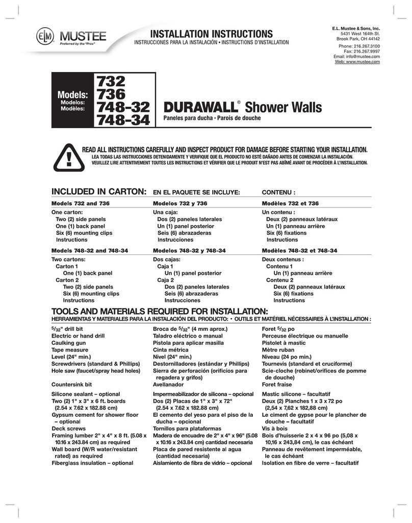
1. The shower receptor must not be installed on exposed floor joists, if there is no sub-floor at the desired location, a
one-piece section of plywood (CDX) the same thickness as the surrounding sub-floor must be securely fastened in
position so that the shower receptor is fully supported. (Fig. B)
HINT: To eliminate “creaking or squeaks” we recommend “Deck” type screws (3” min. length) be used to secure
the sub-floor to the floor joists especially under the shower receptor in the alcove area.
2. As specified in the “ROUGH-IN” illustrations — a 5” (inch) square opening in the sub-floor or slab is required at the
centerlines of the alcove to accept the shower drain body. Drain connection requires 2” (inch) DWV pipe. (Fig. A)
Sl-164 (5•06)
2
TOOLS AND MATERIALS* See back cover page.
ROUGH-IN FRAMING
After you have determined where your MUSTEE SHOWERWALL is to be located you will have to construct the appropriate
alcove. Be sure to plan your rough plumbing requirements (drain-venting-supply lines) at this time. Refer to “ROUGH-IN”
illustrations for dimensions, Fig. A & Fig. B.
After you have constructed your alcove and completed your rough plumbing requirements you are now ready to install the
shower receptor.
HINT: This would be a good time to install Kraft Faced fiberglass insulation or unfaced batting with a 4 mil. (poly) vapor
barrier film between the open studs of your alcove area.
3. Place shower receptor directly on sub-floor or slab, level
receptor in both directions — place level along top edge of
tile flanges — do not use floor area which is tapered for
water drainage.
HINT: You may want to install shower receptor in a bed
of gypsum cement or panel/floor adhesive for
additional support.
4. Seal waste by installing drain seal around 2” (inch) waste
pipe. Apply a lubricant of some kind (Iiquid soap or silicone
sealant works well) to the inside and outside of drain seal
prior to installation. Tamp in place to bottom of drain body
using a 1/4”(inch) diameter rod. Make sure top of drain seal is
even with top of 2” (inch) waste pipe as shown insectional view and in full compliance with local code regulations
pertaining to below floor waste connections. (Fig. C)
5. You have been furnished with (6) six mounting clips to secure the shower receptor. Position (2) two clips per side at stud
centers and securely fasten with screws provided. See Sectional View, Fig. D.
Sl-164 (5•06)
3
After you have installed your shower receptor and have made your sanitary drain-waste-vent stack connections, you are now
ready to assemble and install your (3) three piece Molded Fiberglass Shower Wall unit.
FIG. D
SHOWER WALL
After all of the required hole drilling is completed, it is much easier to assemble the unit outside of the alcove and set in place as
a one-piece unit. If you prefer not to follow this procedure, the Center Panel must be installed first.
A. One of the Side Panels will require drilling for the mixing/control valve handle(s). The showerhead may be located through
the Side Panel or above it (which ever you chose in your rough plumbing). Double check all measurements before you do
any drilling. The drilling should be completed before the unit is installed. Drill from the finished (inside) surface.
B. The Center and Side Panels have a mounting flange that is designed to accept standard “deck” screws, the position
ing of the studs and bracing have been laid-out to give maximum support (horizontally and vertically) behind these flanges.
The mounting flanges have pre-marked holes — to avoid cracking the flange, it is recommended that you pre-drill all of
the holes with a 5/32” (inch) diameter drill bit.
C. To avoid any creaking or bowing that may take place with normal settling of the structure, it is mandatory that every
pre-marked mounting hole be utilized.
D. On the Center Panel, you will notice a groove on the right and left side, going the full height of the panel. We recommend
that a bead of “clear” silicone sealant be applied into each groove, this will ensure a watertight seal when the Side Panel
blades are inserted into these grooves. See drawing, Fig. E.
E. If a shower door (enclosure) is to be installed with this unit, we recommend bonding a piece of 1 x 3 to the backside of each
Side Panel prior to installation of the unit. If a curtain is to be used, the same 1 x 3 reinforcing strip should be used to
“back-up” the mounting brackets. If unit has been installed and no reinforcing strips have been used and you decide to
mount either a shower door or curtain — You must use “Molly” type clinching anchors for all screws. See drawing,
Fig. F & Fig. J.
Sl-164 (5•06)
FIG. E FIG. F
4
