Muth Mirror Systems Signal User manual

Signal
®
Mirror Installation Instructions
2006-2010 Ford Explorer, 2006-2010 Ford Ranger, 2006-2010 Mercury Mountaineer
THE safety accessory of the 21
st
Century.™
P/N 210-0145-0 Re . A2 (8/19/2011), BTV © 2007 Muth Company, LLC
& 2006-2010 Mazda B-Series

Professional Installation Recommended
:
Warranty does not co er damage to the ehicle or mirror housing due to improper installation. Muth Mirror Systems, LLC
(MMS) assumes no responsibility with regard to the accuracy of this information. MMS assumes no liability or responsibility
resulting from improper installation, e en in reliance upon this information. Proper installation is the responsibility of the
installer. It is your responsibility to erify any circuit before interfacing with it using a digital multimeter.
INCLUDED ITEMS:
1-left and 1-right Signal
®
mirror
1-left and 1-right wire h arness
2-wire taps
1-ring connector
1-instruction manual
REQUIRED TOOLS:
Ratchet with e xten sion or ratch eting screwdriver
6 mm socket
7 mm socket
8 mm socket
Socket wrench
-30 orx bit
Large slotted screwdriver
Small slotted screwdriver
Large Phil lips screwdriver
Small Phillips screwdriver
Small pry bar (nylon, non-scratchable)
Gopher rod (wire)
Electrical tape
Wire crimper and stripper
Needle nose pliers
Multimeter or wire tester
Sturdy gloves
Safety glasses or goggles
Utility knife
PROBLEMS OR QUESTIONS?
echnical Assistance is available by calling
Muth Mirror Systems echnicians at:
1-800-844-6616
Monday through Friday
Between 8:00 a.m. and 5:00 p.m. CS
Or through the Muth web site: www.muthco.com
Or via E-mail: techsupport@muthco.com
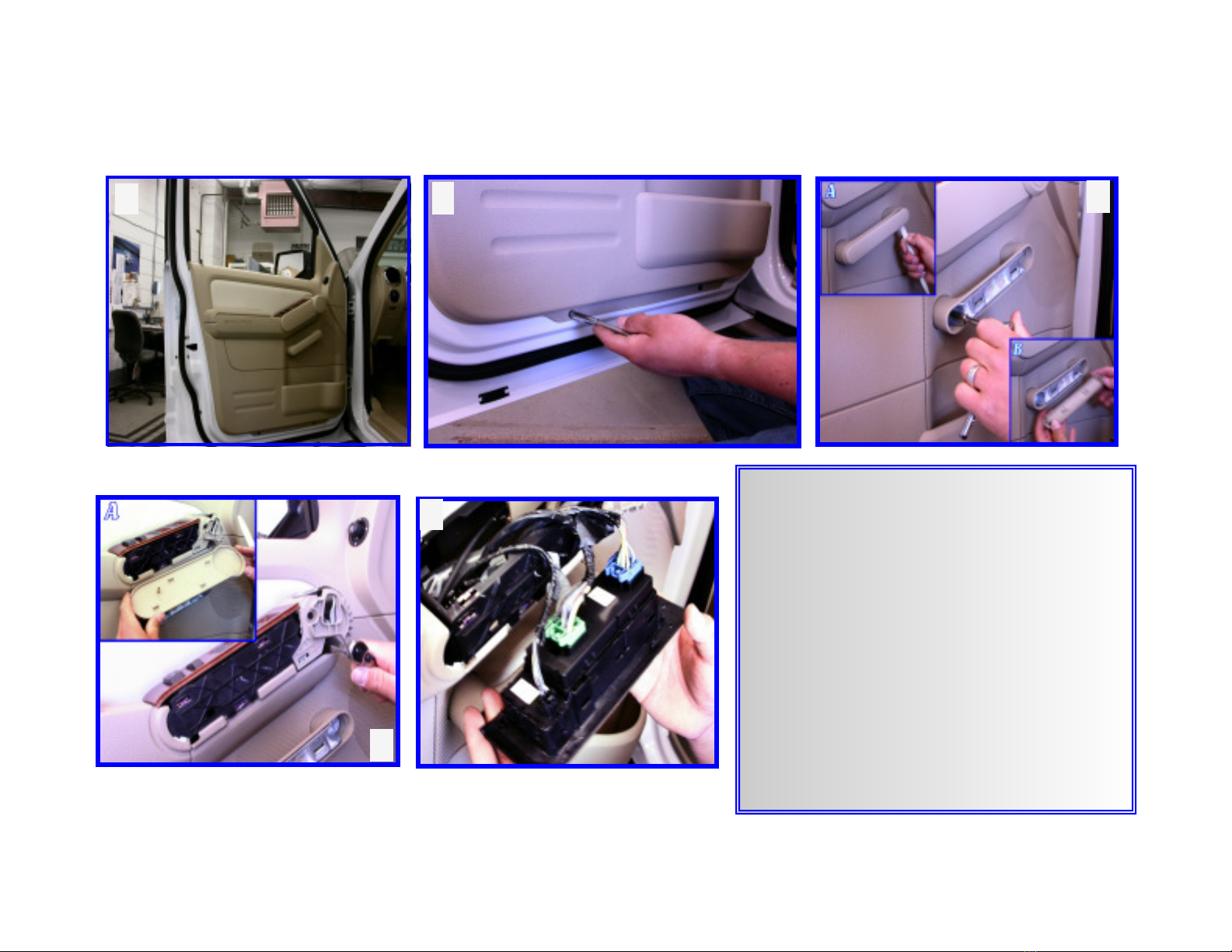
PLEASE READ INSTRUCTIONS PRIOR TO INSTALLATION.
Page 2
*Ranger installation instruction starts on page 10.*
*Explorer / Mountaineer installation instruction starts on page 3*

Page 3
1
Explorer & Mountaineer - Door Panel Removal
4
3
2
1. Start with opening the driver’s side door and low-
ering the window.
2. Remove (2) screws on the bottom of door panel
(7mm Socket).
3. Using a nylon, non-scratchable, pry bar – pry, un-
snap and remove door handle cover (A&B). Re-
move the (2) revealed screws using a 7mm socket.
4. With a nylon, non-scratchable, pry bar – pry, un-
snap and remove control module cover (A). Re-
move the (2) revealed screws using a 7mm socket.
5. Lift control module up and out. urn control
module over and disconnect all wiring connec-
tions.
5

6. Lift the door panel up and off of the door. Hold the door panel a few inches away from the door. Using a needle nose pliers, unclip latch cable (A).
Remove door panel and set it aside.
7. Remove corner trim piece and disconnect wiring connector (A). Secure the mirror housing with one hand and remove the three mirror mounting
nuts from the corner of the door with 11mm socket. Carefully remove the mirror housing from the door. Lay the mirror housing on a, cloth covered,
flat surfaced work bench.
6
Explorer & Mountaineer - Door Panel Removal Continued
7
Page 4

1. Place an ‘X’ on the mirror glass with masking tape to help prevent glass breakage.
With a heater gun (blow dryer), heat around the central portions of the glass (in a cir-
cular motion) for about 30 seconds to help loosen backing plate engagement.
2. Push on the outboard side of the mirror to manually pivot mirror fully inward. Insert
a large flathead screwdriver down between the motor actuator and the backplate mo-
tor mount. Slowly and carefully pry up against mirror and around motor actuator un-
til OE mirror unsnaps. If heated, disconnect heater wires from heater terminals. Lift
up and remove OE mirror.
3. Push in and unsnap flood light lens cover using a small flathead screwdriver (A). Re-
move lens cover and set it aside. Remove foam insulation from housing sail.
4. Using the shorter of the two Signal® mirror harnesses from the wiring kit, guide the
end without the mating connector from inside mirror housing and out through the
housing sail leaving about 4”-6” of wiring inside housing for connection. When
routing the Signal® mirror harness thru, make sure to follow OE wiring passages.
Pull the Signal® mirror harness thru to eliminate any slack inside routing passage.
Secure the Signal® mirror harness on top of the OE wire connector (shown in (A))
using electrical tape. Re-assemble foam insulation onto housing sail. Snap flood light
Lens cover back into place.
Page 5
1
Explorer & Mountaineer - Mirror Replacement
3
2
WARNING: Safety glasses and sturdy glo es are required for mirror replacement.
4

Page 6
5. Connect the Signal® mirror mating connector to the Signal® mirror harness and wrap connectors with the supplied foam wrap (A). If heated, re-
connect the heater wires to the heater terminals on the back of the new Signal® mirror (B). NOTE: There is no polarity so the wires may be in-
terchanged.
6. Position and align the mirror mount onto the motor actuator. Carefully tuck all wiring behind motor actuator. Not doing so, could result in wir-
ing interfering with mirror tra el. Push all anti-vibration tabs inward so that they are inside of mirror housing. Slowly push down on mirror un-
til mirror snaps into place. Firmly press down on all sides of the Signal® mirror to ensure mirror is fully seated and functional.
5
Explorer & Mountaineer - Mirror Replacement Continued
6
WARNING: Safety glasses and sturdy glo es are required for mirror replacement.
A
B

1
Page 7
Explorer & Mountaineer - Wire Routing
WARNING: When routing wires into ehicle, it is extremely important to not let wires get pinched or crushed at any time. A oid
window track and sharp edges at all times. Not doing so may cause circuit shortage problems in the long run.
TIP: A gopher rod (wire) maybe use to assist in the Signal
®
mirror wire harness routing processes.
1. Guide the wire harnesses through the door frame and position the mirror housing assembly on the mirror mount. Bolt the mirror housing to the mir-
ror mount with three mirror mounting nuts (A). WARNING! Do not o er tighten the mirror mounting nuts. Reconnect OE wire harness. Locate
rubber grommet in door jam. Door frame side - push rubber grommet in and pull it out. Pull back a portion of the plastic door insulation to gain ac-
cess to door frame cavity. Locate the small hole (B), route Signal® mirror harness into the small hole and out the access hole vacated by the removal
of the rubber grommet.
2. Remove floor trimpiece. Using a -27 orx bit, remove screw which secures hood release lever and remove hood release lever (A). Unsnap kick panel
to gain access to wiring passages (B).
2
B

TIP: A gopher rod (wire) maybe use to assist
in the Signal
®
mirror wire harness routing
processes.
3. Vehicle frame side - with a pliers, pull back weather
barrier to expose connectors. CAUTION: Careful
not to damage material. Disconnect mating connec-
tors. Using a small flathead screwdriver, push tabs
to disengage wire connector from vehicle frame (A).
With a gopher rod, guide the Signal® mirror har-
ness thru rubber grommet and connector. Recon-
nect mating connectors and fish the Signal® mirror
harness thru access hole into vehicle. Snap mating
connector back into its location. Gently pull the Sig-
nal
®
mirror wire harness to remove any slack in the
wire.
* Before proceeding, please read remainder of
instructions for information regarding wiring
identification and options. *
** Repeat all of the pre ious steps to replace the
factory mirror on the passenger side door with the
new Signal
®
mirror. **
Explorer & Mountaineer - Wire Routing Continued
Page 8
3

TURN ONLY
2. he vehicle’s electrical wiring is located within the wire bundle along the floor board on
the driver side kick panel. Using a utility knife, carefully cut and remove some of the elec-
trical tape to gain access to the wires behind it. Locate the solid GREY w/ BROWN S RIPE
wire within the wire bundle. urn the ignition key so that electrical power is on and acti-
vate the driver side turn indicator. Probe the wir e with the wire tester to verify that flash-
ing turn directional power is present. Label that wire as ‘dri er side indicator’. Locate the
PURPLE w/ ORANGE S RIPE wire. Activate the passenger side turn in dicator and probe
the wire with the wire tester to verify that flashing turn directional power is presen t. Label
that wire as ‘passenger side indicator’.
Explorer & Mountaineer - Wire Identification
GROUNDING WIRES
1. he ground wiring location is located in the driver side kick panel area. Locate the
grounding bolt within the driver side kick panel. Route both Signal
®
mirror wire harnesses
to the driver side kick panel area. Cut and split the red and black wires on both Signal
®
mirror wire harnesses. Route the black wire to the grounding bolt location. Cut both black
wires to length, making sure enough slack is left for splicing. Splice the black wires and
attach them to the supplied grounding ring. Attach the grounding ring to the grounding
bolt on the vehicle frame.
1
2
**Skip to last page for wire splicing procedures**
Page 9

1
Ranger - Door Panel Removal
3
2
1. Start with opening the driver’s side door and lowering the window..
Remove the screw on the lower left hand corner of door panel using
a Phillips screwdriver (A). Continue removing the (2) screws in the
armrest of door panel [Phillips screwdriver] (B).
2. With a nylon, non-scratchable, pry bar - pry around armrest and un-
snap armrest. Lift up armrest and disconnect all wiring connections.
Remove armrest and set it aside.
3. Using a Phillips screwdriver, remove the screw as shown.
4. Pry around panel cover to disengage it. Remove panel cover.
5. Remove (2) screws on panel plate with a Phillips screwdriver. Re-
move panel plate.
6. Lift up and pull out door panel and set it aside.
5 6
B
A 4
Page 10

7. Remove corner trim piece.
8. Disconnect wiring connector. Secure the mirror housing with one hand and remove the three mirror mounting nuts from the corner of the door with
11mm socket. Carefully remove the mirror housing from the door. Lay the mirror housing on a cloth covered, flat surfaced work bench.
7
Ranger - Door Panel Removal Continued
8
Page 11

1. Place an ‘X’ on the mirror glass with masking tape to help prevent glass breakage.
With a heater gun (blow dryer), heat around the central portions of the glass (in a
circular motion) for about 30 seconds to help loosen backing plate engagement.
2. Push on the outboard side of the mirror to manually pivot mirror fully inward. In-
sert a large flathead screwdriver down between the motor actuator and the back-
plate motor mount. Slowly and carefully pry up against mirror and around motor
actuator until OE mirror unsnaps. If heated, disconnect heater wires from heater
terminals. Lift up and remove OE mirror.
3. Using the shorter of the two Signal® mirror harnesses from the wiring kit, guide
the end without the mating connector from inside mirror housing and out
through the housing sail lea ing about 4”-6” of wiring inside housing for con-
nection. When routing the Signal® mirror harness thru, make sure to follow OE
wiring passages. Pull the Signal® mirror harness thru to eliminate any slack in-
side routing passage. Connect the Signal® mirror mating connector to the Signal®
mirror harness (A) and wrap connectors with the supplied foam wrap. If heated,
reconnect the heater wires to the heater terminals on the back of the new Signal®
mirror (B). NOTE: There is no polarity so the wires may be interchanged.
1
Ranger - Mirror Replacement
3
2
WARNING: Safety glasses and sturdy glo es are required for mirror replacement.
A
B
Page 12

4. Position and align the mirror mount onto the motor actuator. Carefully tuck all wiring behind motor actuator. Not doing so, could result in wir-
ing interfering with mirror tra el. Push all anti-vibration tabs so that anti-vibration tabs are inside of mirror housing. Slowly push down on mir-
ror until mirror snaps into place. Firmly press down on all sides of the Signal® mirror to ensure mirror is fully seated and functional.
5. Route the Signal® mirror harness around the OE wires as shown.
4
Ranger - Mirror Replacement Continued
5
WARNING: Safety glasses and sturdy glo es are required for mirror replacement.
Page 13

1
Ranger - Wire Routing
WARNING: When routing wires into ehicle, it is extremely important to not let wires get pinched or crushed at any time. A oid
window track and sharp edges at all times. Not doing so may cause circuit shortage problems in the long run.
TIP: A gopher rod (wire) maybe use to assist in the Signal
®
mirror wire harness routing processes.
1. Using a 6mm socket, remove the (4) speaker screws. Disconnect speaker wire and remove speaker to gain access to wire routing passage.
2. Guide the wire harnesses through the door frame and position the mirror housing assembly on the mirror mount. Bolt the mirror housing to the mir-
ror mount with three mirror mounting nuts (A). WARNING! Do not o er tighten the mirror mounting nuts. Reconnect OE wire harness (B).
Route the Signal® mirror harness down in between door frame as shown in (C).
2
B
A
C
Page 14

TIP: A gopher rod (wire) maybe use to assist in the Signal
®
mirror wire harness routing processes.
3. Using a push-up tool, remove plastic insert located in the kick panel.
4. With a nylon, non-scratchable, pry bar - lift up on the floor trim partial-
ly, unsnap and remove kick panel.
5. With a gopher rod, guide the Signal® mirror harness thru rubber grom-
met and into vehicle as shown. Gently pull the Signal
®
mirror wire har-
ness to remove any slack in the wire. CAUTION: Careful not to
damage material.
6. o gain access to the wiring location, the knee panel and plate need to
be removed. Using a -30 orx bit, remove the (2) screws holding the
knee panel in place. Unsnap and remove knee panel. Using an 8mm
socket, remove the (5) screws around the knee plate and remove knee
plate.
* Before proceeding, please read remainder of instructions for infor-
mation regarding wiring identification and options. *
** Repeat all of the pre ious steps to replace the factory mirror on the
passenger side door with the new Signal
®
mirror. **
Ranger - Wire Routing Continued
3
6
5
4
Page 15

Ranger - Wire Identification
GROUNDING WIRES
1. he groun d wiring location is located in the driver side kick panel area. Locate the grounding
bolt within the drive r side kick panel. Route both Signal
®
mirror wire harnesses to the driver side
kick panel area. Cut and split the BLACK w/ RED RACE and BLACK wires on both Signal
®
mir-
ror wire harnesses. Route the BLACK wire to the grounding bolt location. Cut both BLACK wires
to length, making sure enough slack is left for splicing. Splice the BLACK wires and attach them to
the supplied grounding ring. Attach the groundin g ring to the grounding bolt on the vehicle
frame.
1
Page 16

2a. he vehicle’s electrical wiring is located within the wire bundle along the steering column. Locate the left-front: LIGH GREEN w/ WHI E S RIPE
(left-rear: LIGH GREEN w/ ORANGE S RIPE - includes brake) wire within the wi re bundle. urn the ignition key so that electrical power is on
and activate the driver side turn indicator. Probe the wire with the wire tester to verify that flashing turn directional power is present. Label that
wire as ‘dri er side indicator’. Find the right-front: WHI E w/ LIGH BLUE S RIPE (right-rear: O RANGE w/ LIGH BLUE S RIPE - includes
brake). Activate th e passenger side turn indicator and probe the wire with the wire tester to verify that flashing turn directional power is present.
Labe l that wire as ‘passenger side indicator’.
2
2006 Ranger & Mazda B-Series
2b. h e vehicle’s electrical wiring is located within the wire bundle alon g the steering column.
Locate the solid VIOLE w/ WHI E S RIPE wire within the wire bundle. urn the ignition
key so that electrical power is on and activate the driver side turn indicator. Probe the wire
with the wire tester to verify that flashing turn directional power is present. Label that wire
as ‘dri er side indicator’ . NOTE: There are (3) iolet w/ white stripe wires in this location.
Please erify with wire tester to confirm you ha e correctly identified the correct wire. Lo-
cate the GREY w/ YELLOW S RIPE wire. Activate the passenger side turn indicator and
probe the wire with the wire tester to verify that flashing turn directional power is present.
Labe l that wire as ‘passenger side indicator’.
2007-2010 Ranger & Mazda B-Series
(can include brake so probe carefully)
2c. h e vehicle’s electrical wiring is located within the wire bundle along the steering column. Locate the left-front: BLUE w/ GREEN S RIPE (left-
rear : GRAY w/ BROWN S RIPE - includes brake) wire within the wire bundle. urn the ignition key so that electrical power is on and activate the
driver side turn indicator. Probe the wire with the wire tester to verify that flashing turn directional power is presen t. Label that wire as ‘dri er
side indicator’. Find the right-front: YELLOW w/ VIOLE S RIPE (right-rear: VIOLE w/ ORANGE S RIPE - includes brake). Activate the pas-
senger side turn indicator and probe the wire with the wire tester to verify that flashing turn directional power is present. Label that wire as
‘passenger side indicator’.
2006-2010 Sportrac, Explorer & Mountaineer
Please refer to the appropriate model and year, of your vehicle, to get the correct wire color information

12 3 4
USE THE INCLUDED WIRE TAPS AND FOLLOW THE FOUR STEPS ABOVE TO SPLICE INTO THE TURN INDICATOR WIRES
A. Make sure the harnesses are routed securely and enough slack is left for splicing.
B. Splice the BLACK w/ RED RACE wire from the driver side harness into the wire previously labeled ‘driver side indicator’.
C. Splice the BLACK w/ RED RACE wire from the passenger side harness into the wire previously labeled ‘passenger side indicator’.
D. Activate each turn indicator to verify that the Signal
®
mirrors are working properly.
E. Reconnect all original wiring. urn the ignition power to on, check to verify all features are working properly.
F. Replace the plastic door frame moldings, trim, door panels, and all accessories.
Page 17
PROFESSIONAL INSTALLATION RECOMMENDED
Warranty does not cover damage to vehic e or mirror housing due to improper insta ation. Muth Mirror Systems, LLC (MMS) assumes no
responsibi ity with regard to the accuracy of this information. MMS assumes no iabi ity or responsibi ity resu ting from improper insta a-
tion, even in re iance upon this information. Proper insta ation is the responsibi ity of the insta er. It is your responsibi ity to verify any cir-
cuit before interfacing with it using a digita mu timeter.
WARRANTY STATEMENT
The Signal® Mirror is warranted to be free from defects in materials and workmanship for a period of three years or 6,000 miles (whichever
comes first) from date of sale to original purchaser. This warranty excludes labor, broken glass, or other situations that cause harm to the
product after it has been shipped from the factory, such as damage, unreasonable use, modifications, or alterations. In the event of a de-
fect, Muth reserves the right to evaluate the problem though Quality Control and, at Muth’s discretion, replace the defective product. Any
warranty or replacement part will be charged to the customer when shipped. Credit will be given when the defective part is returned to and
received by Muth , and the replacement is warranted.
Muth products are protected by these, and other pending, United States Patents: 6,076,948; 6,257,746; 7,104,676; 7,327,321;
6,749,325; 7,241,037; 7,192,172; 7,273,307; 7,416,318; 6,045,243; D394,833; D409,540; D428,373; D426,506; D430,088; D426,507; D428,372;
D429,202; D428,842; D425,466; D427,128
Table of contents
Popular Automobile Accessories manuals by other brands

Cruz
Cruz Evo Rack Alu A17-126 Assembly instructions

Ranger design
Ranger design 3068-DL installation guide

Metra Electronics
Metra Electronics 95-6549 installation instructions

Whispbar
Whispbar K758W Fitting instructions

Safe Fleet
Safe Fleet Prime Design VBB FT21B manual

Michelin
Michelin 12290 quick start guide