FuelTech Nano PRO User manual

OWNER'S
MANUAL
NanoPRO - Capa Manual Online EN.pdf 1 09/03/2023 07:55:17

NANO PRO
2
1. Index
2. Presentation...................................................................................................................................................................................3
3. Warnings and Warranty Terms ..........................................................................................................................................................4
4. Characteristics................................................................................................................................................................................5
4.1 Package contents.....................................................................................................................................................................5
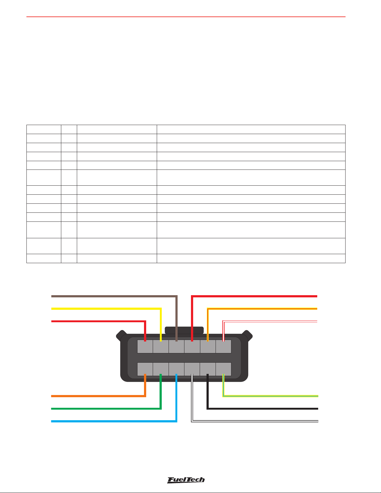
5. Nano PRO Electrical Installation.........................................................................................................................................................6
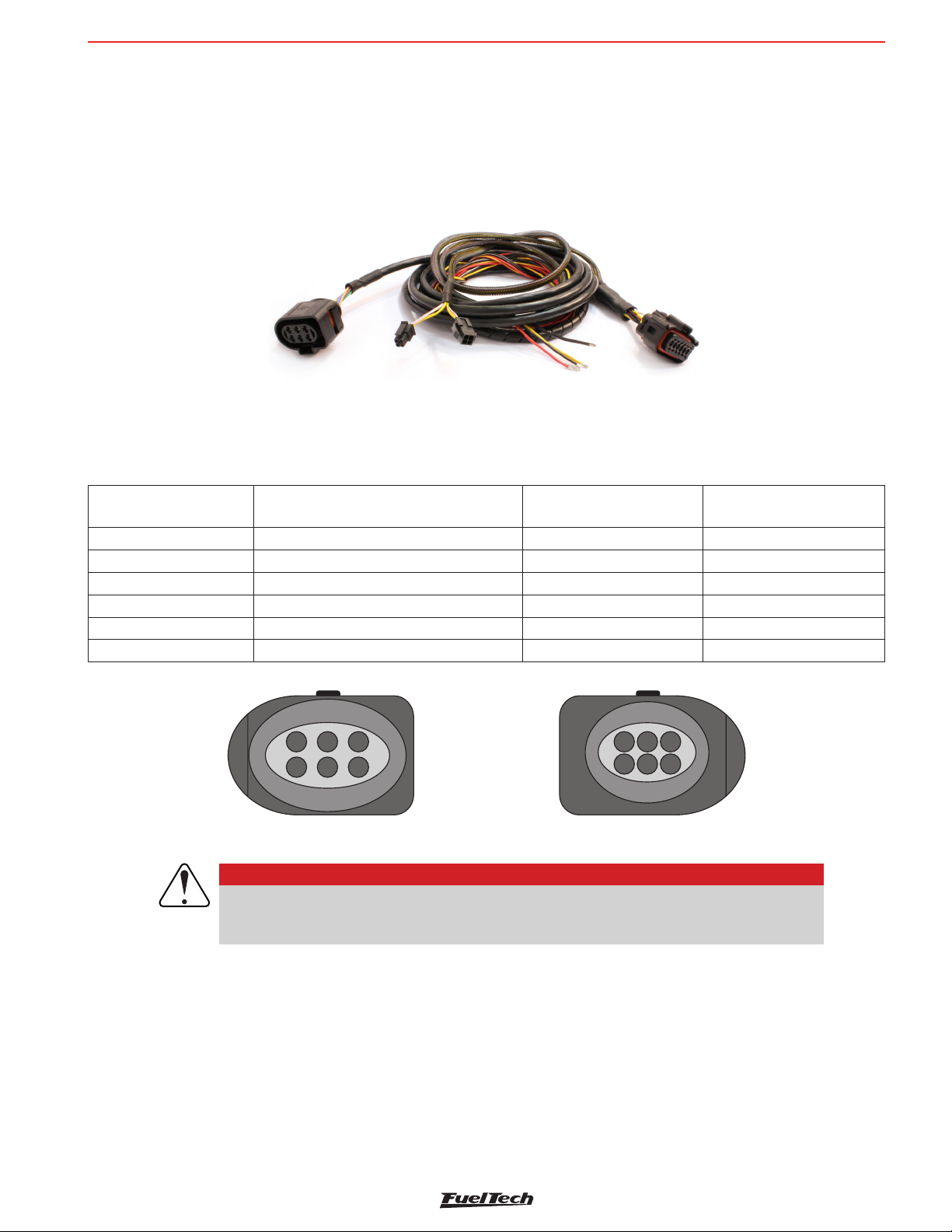
5.1 Adapter harnesses ....................................................................................................................................................................7
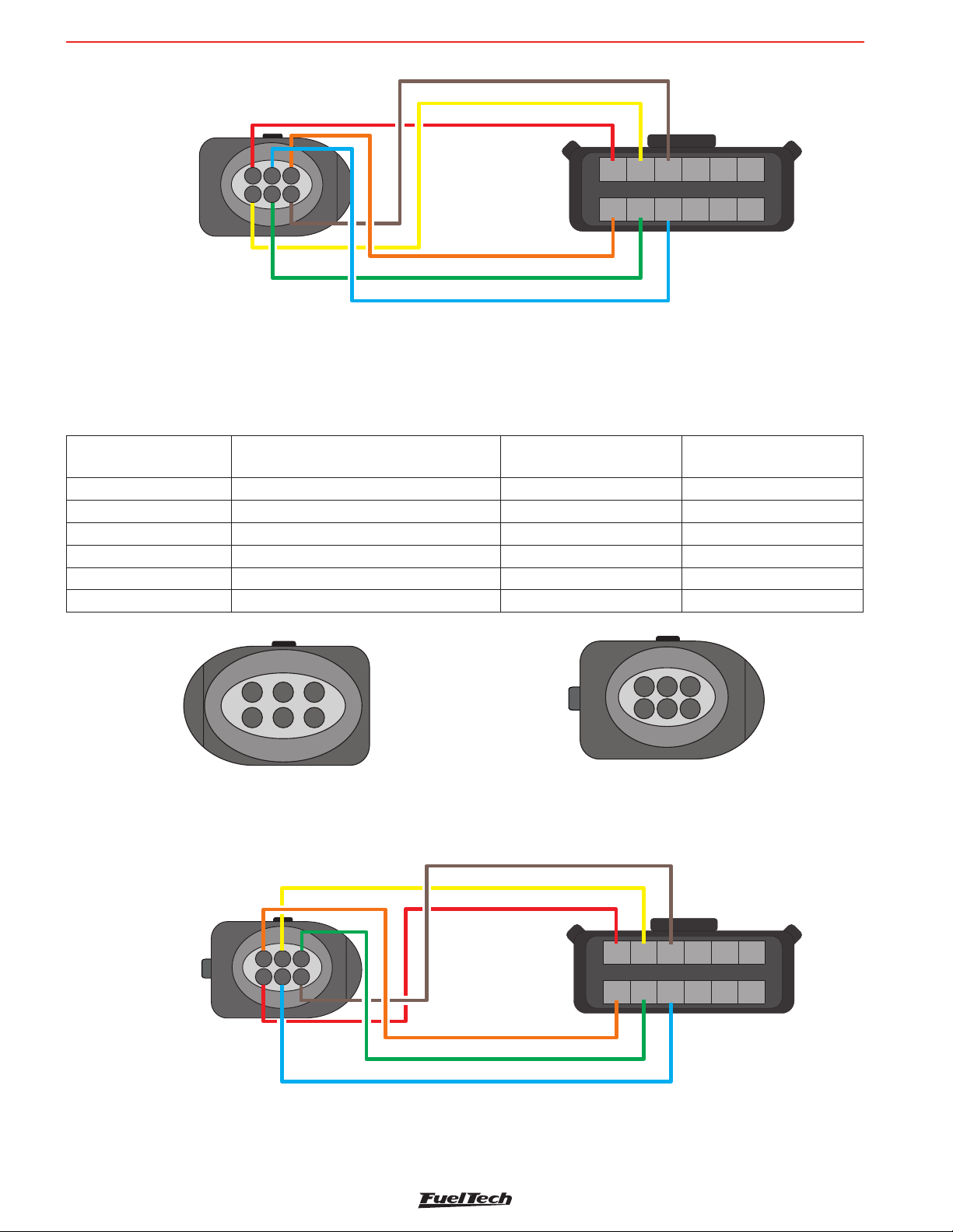
5.2 Replacement of Bosch LSU sensor connector 4.2 for 4.9..............................................................................................................7
5.2 Replacement of Bosch LSU sensor connector 4.2 for 5.2..............................................................................................................8
5.3 Replacement of Bosch LSU sensor connector 4.2 for NTK.............................................................................................................9
6. Wide Band O2 Sensor ..................................................................................................................................................................10
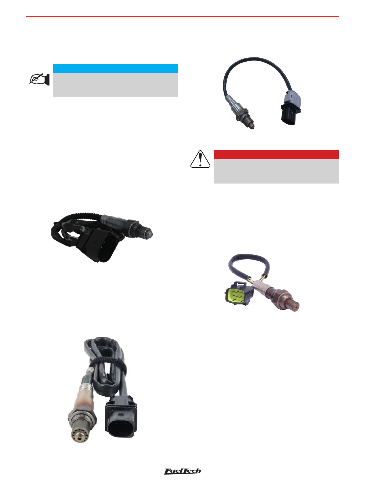
6.1 BOSCH LSU 4.2 O2 Sensor ....................................................................................................................................................10
6.2 BOSCH LSU 4.9 O2 Sensor ....................................................................................................................................................10
6.3 BOSCH LSU 5.2 O2 Sensor ....................................................................................................................................................10
6.4 NTK O2 Sensor......................................................................................................................................................................10
6.5 O2 Sensor Installation .............................................................................................................................................................11
7. CAN Communication.....................................................................................................................................................................11
8. Conguration through the Nano PRO Interface ..................................................................................................................................12
8.1 Dashboard conguration..........................................................................................................................................................12
8.2 Display conguration ...............................................................................................................................................................13
8.3 Heating setup.........................................................................................................................................................................13
8.4 O2 sensor conguration ..........................................................................................................................................................14
8.5 Manual .................................................................................................................................................................................14
8.6 Language..............................................................................................................................................................................14
8.7 About ...................................................................................................................................................................................15
9. Conguration via the FTManager Interface ........................................................................................................................................16
9.1 Datalogger Channels...............................................................................................................................................................17
9.2 Nano PRO Software Update .....................................................................................................................................................18
10. Lambda Readings analog outputs ...................................................................................................................................................19
10.1 Lambda Analog Output in Volts – 5.14 to 17.6AFR...................................................................................................................19
10.2 Lambda Analog Output in Volts – 8.7 to 16.2 AFR (default)........................................................................................................19
10.3 Lambda Analog Output in Volts – 9.6 to 19.1 AFR....................................................................................................................19
10.4 Lambda Analog Output in Volts – 9.6 to 58.8 AFR....................................................................................................................19
10.5 Lambda Analog Output in Volts – 9.6 to 146.9 AFR..................................................................................................................19
11. Analog output Lambda/AFR ...........................................................................................................................................................19
12. Nano PRO Codes .........................................................................................................................................................................20
12.1 Informative Codes.................................................................................................................................................................20
12.2 Error Codes .........................................................................................................................................................................20
13. Fixing template (in)........................................................................................................................................................................21

NANO PRO
3
2. Presentation
FuelTech Nano PRO is a tool used for monitoring and datalogging of air to fuel ratios on combustion engines. The
device is able to read and share with the ECU the following oxygen sensors: BOSCH LSU 4.2 / BOSCH LSU 4.9 /
BOSCH 5.2 and NTK wide-band sensor.
Besides it’s multiple types of O2 sensors compatibility, the Nano PRO is also a dashboard, allowing the con guration
of up to 5 screens to display information sent by the ECU (FTCAN 2.0), or work as button to activate various ECU
functions.
Monitor the engine’s air/fuel mixture and explore the complementary features, displaying complementary info or
saving inputs by activating buttons thought it’s screen.
The new Nano PRO is fully compatible with the WB-O2 NANO harness, sharing same connector and pinout.
When stand-alone, the display will only show the air/fuel mix information.
Bosch sensors are self-calibrating, while NTK sensors require an air free calibration, see the manual for information
about the procedure.
IMPORTANT
After the Bosch LSU sensor is installed make sure you select the correct sensor. This will
prevent sensor damage and reading errors.
There are differences between AFR (air fuel ratio) from the Bosch LSU Sensor 4.2 and 4.9, so it’s necessary to
correctly con gure the Bosch LSU Sensor type.

NANO PRO
4
3. Warnings and Warranty Terms
The use of this equipment implies the total accordance with the terms described in this manual and exempts the
manufacturer from any responsibility regarding to product misuse.
Read all the information in this manual before starting the product installation.
This product must be installed and programmed by specialized auto shops and/or personnel with experience
on engine preparation and tuning.
Before starting any Electrical installation, disconnect the battery.
The inobservance of any of the warnings or precautions described in this manual might cause engine damage and
lead to the invalidation of this product warranty. The improper adjustment of the product might cause engine damage.
This product does not have a certication for the use on aircrafts or any ying devices, as it has not been designed
for such use purpose.
In some countries where an annual inspection of vehicles is enforced, no modication in the original fuel injection
system is permitted. Be informed about local laws and regulations prior to the product installation.
Limited Warranty
All products manufactured by FUELTECH are warranted to be free from defects in material and workmanship for one
year following the date of original purchase. Warranty claim must be made by original owner with proof of purchase
from authorized reseller.
This warranty does not include sensors or other products that FUELTECH carries but did not manufacture. If a
product is found defective, such products will, at FUELTECH’s option, be replaced or repaired at cost to FUELTECH.
All products alleged by Purchaser to be defective must be returned to FUELTECH, postage prepaid, within one year
warranty period.
This limited warranty does not cover labor or other costs or expenses incidental to the repair and/or replacement
of products or parts.
This limited warranty does not apply to any product which has been subject to misuse, mishandling, misapplication,
neglect (including but not limited to improper maintenance), accident, improper installation, tampered seal,
modication (including but not limited to use of unauthorized parts or attachments), or adjustment or repair performed
by anyone other than FUELTECH.
The parties hereto expressly agree that the purchaser’s sole and exclusive remedy against FUELTECH shall be for
the repair or replacement of the defective product as provided in this limited warranty. This exclusive remedy shall
not be deemed to have failed of its essential purpose so long as FUELTECH is willing and able to repair or replace
defective goods.
FUELTECH reserves the right to request additional information such as, but not limited to, tune up and log les in
order to evaluate a claim.
Seal violation voids warranty and renders loss of access to upgrade releases.
Manual version 1.0 – March/2023

NANO PRO
5
1.83 in
1.48 in
2.64 in
4. Characteristics
• Water proof (IP67 Certied)
• 2” display with resistive touchscreen
• Lambda readings shown on the display (2.94 to 146.9 AFR Gas)
• CAN communication with Power FT ECU’s
• Analog output 0-5V
• Compatible with BOSCH 4.2 / 4.9 / 5.2 O2-sensors and NTK sensor
• Congurable operating range
Lambda (0.21 - 9.99)
AFR Methanol (1.35 - 64.6)
AFR Gasoline (3.09 - 146.9)
AFR Ethanol (1.89 - 89.9)
• Dimensions: 2.64” x 1.83” x 1.48” (in)
IMPORTANT
Installation MUST use the screws that come with the product. Out of specication screws
may damage the housing, causing loss of warranty.
4.1 Package contents
• Nano PRO module
• Instructions manual
• 4 screws for xation

NANO PRO
6
5. Nano PRO Electrical Installation
The Nano PRO has a 12-way connector with 3 wire groups. One of them has the connector for the O2 sensor, the
second makes the CAN communication with Power FT ECU’s and the third is responsible for power and analog output.
By default, the analog output is set to values of 8.7AFR to 16.2AFR Gas, but can be congured to 5.1AFR to 17.6AFR
Gas or 9.6AFR to 19.1AFR or 9.6AFR to 58.8AFR or yet 9.6AFR to 146AFR (Gas), if necessary.
See the following wiring diagram for details about connections.
12-way connector
Wire color Pin Connection OBS to Connections
Red 1 O2 sensor O2 sensor pin 6 - IP
Yellow 2 O2 sensor O2 sensor pin 5 - sensor negative signal
Brown 3 O2 sensor O2 sensor pin1 - Sensor positive signal
Red 4 Switched 12V The use of a 10A fuse is recommended
Yellow/Red 5 0-5V Analog Output Analog output proportional to the lambda readings. Used for connection
with data acquisition systems
White/Red 6 CAN CAN (+): connected to Power FT ECU’s CAN port
Orange 7 O2 sensor O2 sensor pin 2 - sensor resistor calibration
Green 8 O2 sensor O2 sensor pin 3 - sensor heater positive
Blue 9 O2 sensor O2 sensor pin 4 - Sensor heater negative signal
Black/
White 10 Chassis/Engine Power
Ground
Engine ground (head/block)
Do not connect it directly to the battery negative.
Black 11 Battery’s Negative Connected directly to the battery negative with no splices. Do not connect
this wire to the chassis engine block or head.
Yellow/Blue 12 CAN CAN (-): connected to Power FT ECU’s CAN port
Power Ground - Black/White
Lambda Output - Yellow/Red
Switched 12V - Red
Battery Ground - Black
7 8 9 10 11 12
1 2 3 4 5 6
O2 sensor - Pin 6 - Red
O2 sensor - Pin 5 - Yellow
O2 sensor - Pin 1 - Brown
CAN HI - Pin 4 - White/Red
O2 sensor - Pin 4 - Blue
O2 sensor - Pin 3 - Green
O2 sensor - Pin 2 - Orange
CAN LOW - Pin 3 - Yellow/Blue
Harness Connector Rear View

NANO PRO
7
5.1 Adapter harnesses
The harness of the Nano PRO is the same as the WB-O2 NANO and is prepared for connection with a BOSCH LSU
4.2 sensor. To use other conditioners, it is necessary to purchase the specic harnesses for each one of them. It is
also possible to buy just the connector kits to replace the LSU 4.2 plug with another one.
Connector Nano PRO
(Pin) - (Wire color) Function wire sensor Connector Bosch LSU
4.2 (Pin)
Connector Bosch LSU
4.9 (Pin)
1 - Red IP 6 1
2 - Yellow Ground sensor signal 5 2
3 - Brown Positive sensor signal 1 6
7 - Orange Calibration resistor sensor 2 5
8 - Green Heat positive signal sensor 3 4
9 - Blue Heat ground signal sensor 4 3
5
26
31
4
Connector Bosch LSU 4.9
2
51
46
3
Connector Bosch LSU 4.2
IMPORTANT
The Nano PRO is factory congured to suit the Bosch LSU 4.2 sensor, if you want to
use another sensor, you need to change the conguration in the Nano PRO software.
This will prevent the sensor from being damaged or reading errors occurring.
5.2 Replacement of Bosch LSU sensor connector 4.2 for 4.9
This procedure is necessary if you want to use a Bosch LSU 4.9 sensor in a Bosch LSU 4.2 Sensor harness. Refer
to table below for sensor pinout:
Harness connector rear view

NANO PRO
8
Connector Nano PRO
(Pin) - (Wire color) Function wire sensor Connector Bosch LSU
4.2 (Pin)
Connector Bosch LSU
5.2 (Pin)
1 - Red IP 6 5
2 - Yellow Ground sensor signal 5 4
3 - Brown Positive sensor signal 1 1
7 - Orange Calibration resistor sensor 2 6
8 - Green Heat positive signal sensor 3 2
9 - Blue Heat ground signal sensor 4 3
5.2 Replacement of Bosch LSU sensor connector 4.2 for 5.2
This procedure is necessary if you want to use a Bosch LSU 5.2 sensor in a Bosch LSU 4.2 Sensor harness. Refer
to table below for sensor pinout:
5
26
31
4
Connector Bosch LSU 5.2
2
51
46
3
Connector Bosch LSU 4.2
Harness connector rear view
5
2
6
31
4
O2 SENSOR - Pin 6 - Red
O2 SENSOR - Pin 5 -Yellow
O2 SENSOR Brown- Pin 1 -
O2 SENSOR - Pin 4 - Blue
O2 SENSOR - Pin 3 -Green
O2 SENSOR - Pin 2 - Orange
Harness Connector Rear View
213456
7891011 12
O2 Sensor
-
BOSCH 4.9
Bosch LSU 4.9 Electrical diagram
5
2
6
31
4
O2 SENSOR - Pin 6 - Red
O2 SENSOR - Pin 5 -Yellow
O2 SENSOR - Pin 1 -Brown
O2 SENSOR - Pin 4 - Blue
O2 SENSOR - Pin 3 -Green
O2 SENSOR - Pin 2 - Orange
Harness Connector Rear View
213456
7891011 12
O2 Sensor
-
BOSCH 5.2
Bosch LSU 5.2 Electrical diagram

NANO PRO
9
Connector Nano PRO
(Pin) - (Wire color) Function wire sensor Connector Bosch LSU
4.2 (Pin) Connector NTK Sensor
1 - Red IP 6 3
2 - Yellow Ground sensor signal 5 1
3 - Brown Positive sensor signal 1 5
7 - Orange Calibration resistor sensor 2 -
8 - Green Heat positive signal sensor 3 8
9 - Blue Heat ground signal sensor 4 6
2
51
46
3
Connector Bosch LSU 4.2
5.3 Replacement of Bosch LSU sensor connector 4.2 for NTK
This procedure is necessary if you want to use a NTK sensor in a Bosch LSU 4.2 Sensor harness. Refer to table
below for sensor pinout:
1
2
4
68
357
Connector NTK Sensor
Harness connector rear view
NTK Sensor Electrical diagram
1
2
4
68
357
O2 SENSOR Red- Pin 6 -
O2 SENSOR Yellow- Pin 5 -
O2 SENSOR Brown- Pin 1 -
O2 SENSOR 3Green- Pin -
Orange - Not Used
Harness Connector Rear View
213456
7891011 12
O2 Sensor
-
NTK
O2 SENSOR Blue- Pin 4 -

NANO PRO
10
6. Wide Band O2 Sensor
Better known as the oxygen sensor, it is responsible for reading
the exhaust air/fuel ratio. This sensor is essential for engine
ne tuning.
Part Number Bosch (Brazil): 0 258 007 057 or 0 258 007
351
VW: 021-906-262-B
6.2 BOSCH LSU 4.9 O2 Sensor
The Bosch LSU 4.9 O2 sensor works the same as the 4.2
6.3 BOSCH LSU 5.2 O2 Sensor
The O2 sensor Bosch LSU 5.2.
6.4 NTK O2 Sensor
This O2 sensor is used in engine laboratories, due to its extreme
accuracy and speed in reading in different AFRs.
This O2 sensor requires an free-air calibration.
Free-air calibration
The NTK O2 sensor needs an open air calibration, so after
con guring in the software it is necessary to connect the sensor
to the Nano PRO and carry out the calibration.
To perform this procedure, rst connect the O2 sensor to the
Nano PRO and leave it out of the exhaust. Turn the ignition on,
and let the NTK O2 sensor heat up for 5 minutes, then access
the sensor setup menu, select NTK, and click on the “calibrate”
button.
The calibration process is executed 5 times to guarantee the
expected result, after the test a message with the result will
appear on the screen. If an error message is displayed, it is
necessary to repeat the calibration procedure.
IMPORTANT
Bosch LSU oxygen sensors are not designed to
run on fuel that contains lead, and their lifespan
is drastically reduced to around 50 to 500 hours.
Part Number Bosch (Brazil): 0 258 017 025
Part Number Bosch (Brazil): 1 928 404 719
Part Number FuelTech: 5005100011
6.1 BOSCH LSU 4.2 O2 Sensor
Bosch LSU 4.2 sensor has an encased heating element and it is
used to measure the air fuel ratio, which determines the lambda
value in the remaining exhaust gas. Its signal indications vary
from 5.14AFR Gas (0,35λ)lambda (rich mixture) to open air
lambda (in nite).
The connector includes a calibration resistor (factory calibrated),
which defines the characteristics of the sensor and it is
necessary for its operation. It is with this resistor that the WB-
O2 Nano automatically calibrates the sensor.
NOTE
Running the engine with the sensor installed to the
exhaust and not connected to the Nano PRO (or
other conditioner) may damage the sensor.

NANO PRO
11
6.5 O2 Sensor Installation
The sensor must be inserted in the exhaust system with its tip exposed to the exhaust gas ow. It must stay in an
angle between 10 to 80 degrees to horizontal position, that is, with its end downward, in such a way that steam
droplets cannot be accumulated between the body of the sensor and its ceramic part, which could cause damage
when the sensor is used. The sensor must not be placed vertically, as it becomes subject to excessive heat.
It is recommended that the sensor is installed at least one (1) meter away from the exhaust manifold to avoid
excessive heat, and at least one (1) meter away from the exhaust external output to avoid incorrect readings caused
by oxygen in the air outside the exhaust system.
Notice that such recommendations are not obligatory, as vehicles with a smaller exhaust system will need to have
the sensor placed closer to the engine.
The sensor must stay away from the cylinder head and from areas where one cylinder might affect the exhaust air
more than the others must. Avoid placing the sensor close to the exhaust manifold joints, as some allow the inow
of air, resulting in incorrect readings.
7. CAN Communication
The Nano PRO has CAN communication, which allows the module to send and read information from the Power FT
ECU’s that are also connected in the network. Included on the Nano harness are two 4-way CAN connectors that
plug and play with other Nano PRO units as well as the Power FT ECU’s.
When connected to the CAN port, the Nano PRO can read what the fuel and the measurement unit (lambda or AFR)
that the ECU is set, adjusting itself to these settings, disabling the analog output and sending the AFR value to ECU
in the range of 2.94 to 149.9 AFR Gas.
In the CAN network, during the O2 sensor heating period, the value displayed in the Power FT ECU’s will be equal
to 0 (zero) and the back of lambda gauge will turn yellow.
In case of any error during work, in addition to the warning on Nano PRO display, the error will be sent via CAN to
the Power FT ECU’s and recorded in “Status Events” log.
To connect the Nano PRO via CAN to Power FT ECU’s simply plug the 4-way cable to the ECU CAN port.

NANO PRO
12
8. Confi guration through the Nano PRO Interface
It is possible to con gure the FuelTech Nano PRO entirely from the screen. Below are a few example screens.
Single O2 sensor gauge O2 sensor with a data
fi eld Three data fi eld One button Two Buttons
Single O2 sensor gauge
Using the interface
To navigate between screens, press the buttons (1) in the lower
corners of the interface.
There are two ways to get into the menu:
a - Press button (1) to change screens until you reach the menu
screen.
b - Press and hold the button (1) for one second to go directly
to the menu.
1 1
8.1 Dashboard con guration
Con gures the number and information of the dashboards. It is
possible to create up to 5 different dashes.
Con gure here the screen that will be the main dash, presented
on startup of the Nano PRO. You can choose the total number of
Dashboards, for that, click on one of the 3 free spaces.
Wideband Meter
There are two possibilities for viewing the O2 sensor value.
Ideal range bar: In this option, the O2 sensor value will be
shown on the display and just below a bar with the ideal range
of air/fuel mixture.
NOTE
To display a bigger O2 value on the display, do not
confi gure the ideal range values.
Value only: in this option the O2 sensor value will be very similar
to the WB-O2 Nano. Only the O2 sensor value will be displayed.
In this case, it is possible to con gure the color of the value
shown on the display.
Available colors: White, Blue, Green, Yellow, red and Orange.
Select which will be the Nano PRO’s main dash screen. It’s
possible to con gure any of ve screens as the main screen.

NANO PRO
13
Button
Select which buttons will be triggered in each dash. It is possible
to con gure up to 2 buttons per screen.
After each con guration it is necessary to go to the last screen
and click on the save button.
NOTE
When the screen remains idling with no input from
the user for longer than 10 seconds, the action
is canceled and the interface returns to the main
screen.
8.2 Display con guration
In this menu you can choose the screen lighting in day and night
modes. These values are independent of the ECU, that is, the
day and night values can be different between ECU and Nano
PRO Switching between modes can be activated by a button
on the Nano PRO screen or come directly from the ECU via the
FTCAN 2.0 network.
After lighting setup, the display calibration screen will appear.
It is recommended that it be done on the rst installation and
whenever you notice dif culty in touching the screen.
8.3 Heating setup
O2 sensor heating is essential for starting the lambda sensor
reading. On the Nano PRO there are 3 heating modes:
Normal: Standard heating currently used by the WB-O2 Nano.
This is the recommended mode for FuelTech ensuring a longer
O2 sensor life.
It is possible to choose one of the three parameters to start
the heating in automatic mode (whenever it is turned on), by
temperature or RPM.
Data gauge
Select which data will be displayed in each dash. It is possible
to con gure up to 3 parts of information per screen with different
sizes and positions.
If necessary, also con gure the minimum and maximum values
for each con gured information. These alerts are displayed on
the Nano PRO screen and are independent of the ECU, and
may be different values from those con gured in each module.
IMPORTANT
Buttons to work correctly, it is necessary to
con gure the inputs in the ECU map in the
FTManager software.
Fast heating, uses a high current to shorten the heating time. By
using this option the O2 sensor life will be drastically reduced.
It is possible to choose one of the three parameters to start
the heating in automatic mode (whenever it is turned on), by
temperature or RPM.

NANO PRO
14
Limited: Limits heating current to 2, 2.5, and 3 Amps
It is possible to choose one of the three parameters to start
the heating in automatic mode (whenever it is turned on), by
temperature or RPM.
8.4 O2 sensor con guration
Select the model of the O2 sensor installed in the car. On the
next screen con gure the installation position.
The next step is to de ne the unit, fuel type and also the working
scale (analog output).
Procedure for replacing the Lambda O2-sensor
Perform the procedures described below to change the probe:
a - Disconnect the old O2 sensor and remove it.
b - Change the con guration for the new O2 sensor on the
Nano PRO.
c - Turn off the module.
d - Connect the new O2 sensor.
e - Turn on the Nano PRO.
Free-air calibration - NTK Sensor
The NTK O2 sensor needs an open air calibration, so after
con guring in the software it is necessary to connect the sensor
to the Nano PRO and carry out the calibration.
To perform this procedure, rst connect the O2 sensor to the
Nano PRO and leave it out of the exhaust. Turn the ignition on,
and let the NTK O2 sensor heat up for 5 minutes, then access
the sensor setup menu, select NTK, and click on the “calibrate”
button.
The calibration process is executed 5 times to guarantee the
expected result, after the test a message with the result will
appear on the screen. If an error message is displayed, it is
necessary to repeat the calibration procedure.
Possible errors after calibration - NTK Sensor
Current highest 4.3 -> faulty sensor
Current below 3.2 -> sensor is not Free-air
Hour-meter - NTK Sensor
This function allows checking the usage time of the probe
installed in the equipment. There is a RESET button to reset
the usage time count.
8.5 Manual
Through the interface there is a QR Code to download the
manual in its complete version with all the necessary information
for the operation of the Nano PRO.
8.6 Language
Fueltech Nano PRO has the possibility of changing language
for the interface.

NANO PRO
15
8.7 About
This menu shows the O2 sensor usage time and the average
heating time, as well as the hardware, software and serial number
of the Nano PRO. It is also possible to reset the O2 sensor usage
time by clicking on the “Reset” button.

NANO PRO
16
9. Confi guration via the FTManager Interface
To con gure the Nano PRO through the FTManager software, follow the steps described below:
a - Open the map in FTManager Software
b - Access the “Tools” menu and then click on “External Modules” and locate “Nano PRO and open the con guration
screen.
This screen is divided into four distinct parts.
1 - Dashboard con guration: Allows you to con gure the 5 dashboard screens with the data you deem necessary,
as well as de ne which will be the main screen.
2 - Advanced Settings: There are three tabs with all the necessary settings for the Nano PRO to operate correctly
- Display and language: select the language of the Nano PRO and set the brightness levels for day and night
mode.
- Heating: adjusts the O2 sensor heating mode and sets the parameters of RPM and minimum temperature
for the start of heating.
- O2 sensor: de nes which sensor will be used, Unit of measure and the Range of the analog output.
3 - Buttons and Nano PRO selection: there are four buttons for reading and writing the settings in the Nano PRO
memory as well as selecting which device is being con gured (if you have more than one Nano PRO on the
CAN network).
4 - Serial number and hardware and rmware version.
1 3
42

NANO PRO
17
Con guration to use Nano PRO out of the CAN Network
Nano PRO allows the selection of the display unit and O2 sensor reading scale, but, these settings are read from
the Power FT ECU’s during its initialization. In case it is removed from the CAN network, Nano PRO goes back to
factory con guration.
9.1 Datalogger Channels
There are 3 log channels for each O2 sensor tted to the vehicle, which record information about the O2 sensor
heating. With these channels it is possible to have a complete diagnosis, letting you know if the sensor is installed
in the correct position, for example.
Sensor heater PWM: Records the percentage of duty cycle applied to the O2 sensor heater
Sensor Temperature: Records the internal temperature of the sensor
Sensor Resistance: Records the internal resistance in Ohms of the sensor

NANO PRO
18
9.2 Nano PRO Software Update
To update the Nano PRO software, follow the steps described below:
a - Connect the ECU through the USB cable to the computer and open the FTManager Software.
b - Turn ON the ignition key.
c - In the FTManager software, on the “Home” tab, click on the button “Read ECU” (1) to open the map in the
software.
1
d - Open the “Tools” tab and click on the button “CAN Updater” (2);
2
e - A screen for updating the Nano PRO Software will open. On the left (3) of the screen will appear all the equipment
available on the CAN network. Select which Nano PRO will be updated.
f - Click on the button “Update” (4).
g - Wait for the update process to nish, after that the Nano PRO will restart automatically.
h - Check the Nano PRO settings. See “9. Con guration via the FTManager Interface” on page 16, or directly
from the Nano PRO interface.
3
4

NANO PRO
19
AFR (Gasoline) AFR
(Methanol) Lambda
4.120 1.800 0,280
6.470 2.820 0,440
7.640 3.340 0,520
8.530 3.720 0,580
9.260 4.040 0,630
10.000 4.370 0,680
10.580 4.620 0,720
11.170 4.880 0,760
11.760 5.140 0,800
12.500 5.460 0,850
13.380 5.840 0,910
14.700 6.420 1,000
16.320 7.130 1,110
18.380 8.030 1,250
21.020 9.180 1,430
11. Analog output Lambda/AFR
AFR (Gasoline) AFR
(Methanol) Lambda
24.400 10.660 1,660
26.460 11.560 1,800
28.960 12.650 1,970
32.050 14.000 2,180
35.720 15.600 2,430
40.430 17.660 2,750
46.310 20.220 3,150
53.950 23.560 3,670
59.240 25.870 4,030
65.420 28.570 4,450
72.770 31.780 4,950
82.320 35.950 5,600
110.250 48.150 7,500
167.870 73.320 11,420
343.250 149.910 23,350
470.400 205.440 32,000
Lambda AFR Gasoline AFR Methanol/Ethanol Volts
(V)
0,35 5,14 2,3 0,20
1,20 17,6 7,7 4,80
10.3 Lambda Analog Output in Volts – 9.6 to
19.1 AFR
Lambda AFR Gasoline AFR Methanol/Ethanol Volts
(V)
0,65 9,6 4,2 0,20
1,30 19,1 8,3 4,80
10.4 Lambda Analog Output in Volts – 9.6 to
58.8 AFR
Lambda AFR Gasoline AFR Methanol/Ethanol Volts
(V)
0,65 9,6 4,2 0,20
4,00 58,8 25,7 4,80
10.5 Lambda Analog Output in Volts – 9.6 to
146.9 AFR
Lambda AFR Gasoline AFR Methanol/Ethanol Volts
(V)
0,65 9,6 4,2 0,20
9,99 149,9 64,1 4,80
When there is an output reading error, the analog output locks
at 0.00V. Thus, it is possible to know if there is any problem
or error in the equipment. To congure this output on external
equipment, it is necessary to supply the rst and last values of
the table above.
10.2 Lambda Analog Output in Volts – 8.7 to
16.2 AFR (default)
Lambda AFR Gasoline AFR Methanol/Ethanol Volts
(V)
0,59 8,7 3,8 0,20
1,10 16,2 7,1 4,80
10. Lambda Readings analog outputs
10.1 Lambda Analog Output in Volts – 5.14 to
17.6AFR

NANO PRO
20
Description Procedure
Sensor disconnected or damaged
- Check the wiring harness.
- Check connection between harness and sensor plugs.
- Replace the sensor.
Short circuit with the VCC
- Check the wiring harness.
- Check and improve ground or power.
- Check the connection between the harness and sensor plugs.
- Replace the sensor
Heater Short circuit with the GND
- Check the wiring harness.
- Check and improve ground or power.
- Check the connection between the harness and sensor plugs.
- Replace the sensor
Signal Short circuit with the GND
- Check the wiring harness.
- Check the connection between the harness and sensor plugs.
- Check Spark Plugs, Spark Plug Cables.
- Check where the harness passes through to look for possible damage.
- Replace the sensor.
Signal Short circuit with the VCC
- Check the wiring harness.
- Check the connection between the harness and sensor plugs.
- Check Spark Plugs, Spark Plug Cables.
- Replace the sensor.
Sensor not con gured - Con gure an available sensor model see “8.4 O2 sensor con guration” on page 14
12. Nano PRO Codes
12.1 Informative Codes
When turning Nano PRO power on, the following information will be displayed:
Product name
Measurement unit (Lambda, AFR gasoline, AFR alcohol or AFR Methanol)
Analog output scale (as seen on chapter 6)
Cylinder identi cation (when connected via CAN with Power FT ECU’s): tells which cylinder the conditioner is reading,
when used for individual cylinder adjustment.
Then the word HEATING indicates the O2 sensor heating for operation.
After heated, the word HI appears when AFR above 146.9 AFR Gas (64.1 AFR Alcohol) is read.
12.2 Error Codes
VCC = 12V Power / GND = Ground
Other manuals for Nano PRO
1
Table of contents
Other FuelTech Automobile Accessories manuals

FuelTech
FuelTech 9588 User manual

FuelTech
FuelTech Seadoo Rotax 300 2010-2023 User manual

FuelTech
FuelTech SparkPro Operating instructions

FuelTech
FuelTech FT450 User manual

FuelTech
FuelTech 5218 User manual

FuelTech
FuelTech FT500 LITE User manual

FuelTech
FuelTech FTSPARK User manual

FuelTech
FuelTech EGT-8 CAN User manual

FuelTech
FuelTech FTSPARK 750mJ User manual

FuelTech
FuelTech Nano PRO User manual