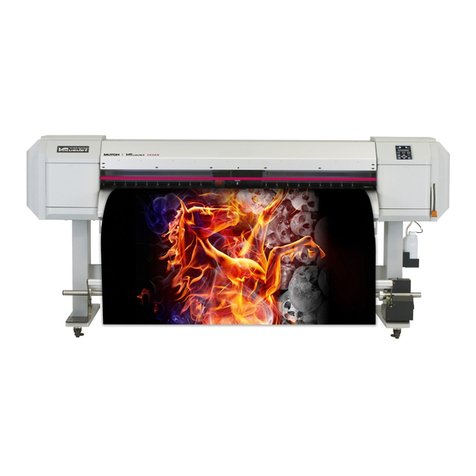
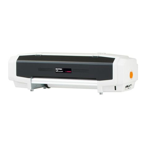
MUTOH Valuevet VJ-628X User manual

VJ628XE-M-00
VJ-628X
MAINTENANCE
MANUAL

Table of contents 2
Table of contents VJ628XE-M-00
1 Safety Instructions
1.1 Introduction . . . . . . . . . . . . . . . . . . . . . . . . . . . . . . . . . . . . . 11
1.2 Types and Meanings of Warnings . . . . . . . . . . . . . . . . . . . 11
1.3 Warning Labels . . . . . . . . . . . . . . . . . . . . . . . . . . . . . . . . . . 12
1.3.1 Location and Type of Warning Labels. . . . . . . . . . . . . . 12
2 Troubleshooting
2.1 Introduction . . . . . . . . . . . . . . . . . . . . . . . . . . . . . . . . . . . . . 14
2.2 Troubleshooting with Error Messages. . . . . . . . . . . . . . . . 15
2.2.1 Operation Status . . . . . . . . . . . . . . . . . . . . . . . . . . . . . . 15
2.2.2 Errors with Message . . . . . . . . . . . . . . . . . . . . . . . . . . . 17
2.2.3 Errors Requiring Reboot . . . . . . . . . . . . . . . . . . . . . . . . 21
2.2.4 Error Messages during File Transmission. . . . . . . . . . . 32
2.3 Troubleshooting Without Error Messages . . . . . . . . . . . . 34
2.3.1 Initial Operation Problems . . . . . . . . . . . . . . . . . . . . . . . 34
2.3.2 Media Feed Problems . . . . . . . . . . . . . . . . . . . . . . . . . . 38
2.3.3 Printing Problems . . . . . . . . . . . . . . . . . . . . . . . . . . . . . 39
2.3.4 Noise Problems . . . . . . . . . . . . . . . . . . . . . . . . . . . . . . . 51
2.3.5 Online Function Problems . . . . . . . . . . . . . . . . . . . . . . . 54
2.3.6 Other Problems . . . . . . . . . . . . . . . . . . . . . . . . . . . . . . . 55
2.3.7 Problems in Using MUTOH Service Assistance . . . . . . 57
3 Parts Replacement
3.1 Introduction . . . . . . . . . . . . . . . . . . . . . . . . . . . . . . . . . . . . . 62
3.2 Removing Covers. . . . . . . . . . . . . . . . . . . . . . . . . . . . . . . . . 63
3.2.1 Removing Top Cover. . . . . . . . . . . . . . . . . . . . . . . . . . . 64
3.2.2 Removing Side Cover . . . . . . . . . . . . . . . . . . . . . . . . . . 65
3.3 Replacing Cover section . . . . . . . . . . . . . . . . . . . . . . . . . . 67
3.3.1 Replacing Panel Board . . . . . . . . . . . . . . . . . . . . . . . . .67
3.3.2 Replacing Cover Switch Assy . . . . . . . . . . . . . . . . . . . . 68
3.3.3 Replacing Switch Lever . . . . . . . . . . . . . . . . . . . . . . . . .69
3.3.4 Replacing Cover R Cable Assy . . . . . . . . . . . . . . . . . . . 70
3.3.5 Replacing Switch Panel Cable Assy . . . . . . . . . . . . . . .71
3.4 Replacing Frame section. . . . . . . . . . . . . . . . . . . . . . . . . . 72
3.4.1 Replacing Media Holder. . . . . . . . . . . . . . . . . . . . . . . . .72
3.4.2 Replacing Scroller Holder Roller Assy. . . . . . . . . . . . . . 73
3.4.3 Replacing Adsorption Fan . . . . . . . . . . . . . . . . . . . . . . .74
3.4.4 Replacing Adsorption Fan Cable. . . . . . . . . . . . . . . . . .75
3.5 Replacing Board Base section . . . . . . . . . . . . . . . . . . . . . 76
3.5.1 Replacing Power Board. . . . . . . . . . . . . . . . . . . . . . . . .76
3.5.2 Replacing AC JUNC-Power Cable Assy . . . . . . . . . . . .77
3.5.3 Replacing IL Dummy Cable Assy . . . . . . . . . . . . . . . . .78
3.5.4 Replacing Main DC Cable Assy. . . . . . . . . . . . . . . . . . . 79
3.5.5 Replacing FG Cable Assy . . . . . . . . . . . . . . . . . . . . . . .80
3.5.6 Replacing AC Inlet. . . . . . . . . . . . . . . . . . . . . . . . . . . . . 81
3.5.7 Replacing Slide Switch . . . . . . . . . . . . . . . . . . . . . . . . . 82
3.5.8 Replacing AC SEL SW Cable Assy. . . . . . . . . . . . . . . . 83
3.5.9 Replacing Cooling FAN . . . . . . . . . . . . . . . . . . . . . . . . . 84
3.5.10 Replacing MAIN Board . . . . . . . . . . . . . . . . . . . . . . . . .85
3.5.11 Replacing JUNCTION Board. . . . . . . . . . . . . . . . . . . . . 87
3.5.12 Replacing JUNC_ID Cable . . . . . . . . . . . . . . . . . . . . . . 88
3.5.13 Replacing JUNC_FFC . . . . . . . . . . . . . . . . . . . . . . . . . . 89
3.5.14 Replacing Inlet AC JUNC Cable Assy . . . . . . . . . . . . . . 90
3.6 Replacing Y Rail part . . . . . . . . . . . . . . . . . . . . . . . . . . . . . 91
3.6.1 Replacing CR Motor. . . . . . . . . . . . . . . . . . . . . . . . . . . . 91
3.6.2 Replacing CR Belt . . . . . . . . . . . . . . . . . . . . . . . . . . . . .93
3.6.3 Replacing CR Motor Relay Assy . . . . . . . . . . . . . . . . . . 96

Table of contents 3
Table of contents VJ628XE-M-00
3.6.4 Replacing CR Origin Sensor . . . . . . . . . . . . . . . . . . . . . 97
3.6.5 Replacing CR Origin Sensor Cable. . . . . . . . . . . . . . . . 98
3.6.6 Replacing Lever Sensor Cable . . . . . . . . . . . . . . . . . . . 99
3.6.7 Replacing Lever Sensor . . . . . . . . . . . . . . . . . . . . . . . 100
3.6.8 Replacing T Fence. . . . . . . . . . . . . . . . . . . . . . . . . . . . 101
3.6.9 Replacing Fence Guide. . . . . . . . . . . . . . . . . . . . . . . . 103
3.6.10 Replacing T Fence Spring. . . . . . . . . . . . . . . . . . . . . . 104
3.6.11 Replacing CR Return Pulley Assy. . . . . . . . . . . . . . . . 105
3.6.12 Replacing Pressure Roller Spring . . . . . . . . . . . . . . . . 107
3.6.13 Replacing Pressure Roller Assy and Pressure Roller Axis
Assy. . . . . . . . . . . . . . . . . . . . . . . . . . . . . . . . . . . . . . . 108
3.6.14 Replacing P_REAR Sensor. . . . . . . . . . . . . . . . . . . . . 109
3.7 Replacing PF section. . . . . . . . . . . . . . . . . . . . . . . . . . . . . 110
3.7.1 Replacing PF Motor. . . . . . . . . . . . . . . . . . . . . . . . . . . 110
3.7.2 Replacing PF Encoder. . . . . . . . . . . . . . . . . . . . . . . . . 111
3.7.3 Replacing PF Encoder Scale. . . . . . . . . . . . . . . . . . . . 112
3.7.4 Replacing X Speed Reduction Belt . . . . . . . . . . . . . . . 113
3.7.5 Replacing PF Speed Reduction Pulley . . . . . . . . . . . . 114
3.7.6 Replacing PF Motor Cable. . . . . . . . . . . . . . . . . . . . . . 115
3.8 Replacing Cursor section . . . . . . . . . . . . . . . . . . . . . . . . . 116
3.8.1 Releasing Carriage Lock . . . . . . . . . . . . . . . . . . . . . . . 116
3.8.2 Removing Carriage Cover . . . . . . . . . . . . . . . . . . . . . 117
3.8.3 Removing CR Board Cover. . . . . . . . . . . . . . . . . . . . . 118
3.8.4 Replacing CR Board . . . . . . . . . . . . . . . . . . . . . . . . . . 119
3.8.5 Replacing CR Encoder . . . . . . . . . . . . . . . . . . . . . . . . 120
3.8.6 Replacing P_EDGE Sensor. . . . . . . . . . . . . . . . . . . . . 121
3.8.7 Replacing Cutter Spring. . . . . . . . . . . . . . . . . . . . . . . . 122
3.8.8 Replacing PG Origin Sensor Cable. . . . . . . . . . . . . . . 123
3.8.9 Replacing Cutter Holder Assy . . . . . . . . . . . . . . . . . . . 124
3.8.10 Replacing Cutter Solenoid Assy . . . . . . . . . . . . . . . . . 125
3.8.11 Replacing Cutter Solenoid Cable. . . . . . . . . . . . . . . . . 127
3.8.12 Replacing Mini Latch . . . . . . . . . . . . . . . . . . . . . . . . . . 128
3.8.13 Replacing Roller Arm Assy . . . . . . . . . . . . . . . . . . . . . 129
3.8.14 Replacing Valve head . . . . . . . . . . . . . . . . . . . . . . . . .130
3.8.15 Replacing Head . . . . . . . . . . . . . . . . . . . . . . . . . . . . . .134
3.8.16 Replacing Head FFC . . . . . . . . . . . . . . . . . . . . . . . . . .139
3.8.17 Replacing Carriage Assy . . . . . . . . . . . . . . . . . . . . . . .141
3.8.18 Replacing Head FG Assy. . . . . . . . . . . . . . . . . . . . . . . 145
3.9 Replacing Cable Guide section. . . . . . . . . . . . . . . . . . . . 146
3.9.1 Replacing Steel Bare. . . . . . . . . . . . . . . . . . . . . . . . . . 146
3.9.2 Replacing Tube Guide Film Assy. . . . . . . . . . . . . . . . .148
3.9.3 Replacing CR FFC. . . . . . . . . . . . . . . . . . . . . . . . . . . . 150
3.9.4 Replacing Ink Tube . . . . . . . . . . . . . . . . . . . . . . . . . . . 152
3.10 Replacing Maintenance . . . . . . . . . . . . . . . . . . . . . . . . . . 157
3.10.1 Replacing Waste Fluid Pump. . . . . . . . . . . . . . . . . . . . 157
3.10.2 Replacing Pump Motor Cable . . . . . . . . . . . . . . . . . . . 158
3.10.3 Replacing Wiper. . . . . . . . . . . . . . . . . . . . . . . . . . . . . .159
3.10.4 Replacing Wiper Solenoid Cable . . . . . . . . . . . . . . . . . 160
3.10.5 Replacing Wiper Solenoid . . . . . . . . . . . . . . . . . . . . . . 161
3.10.6 Replacing Cap Head Assy. . . . . . . . . . . . . . . . . . . . . .163
3.10.7 Replacing Maintenance Assy. . . . . . . . . . . . . . . . . . . . 164
3.10.8 Replacing Waste Fluid Tank . . . . . . . . . . . . . . . . . . . .165
3.11 Replacing IH . . . . . . . . . . . . . . . . . . . . . . . . . . . . . . . . . . . 166
3.11.1 Removing Pump stay. . . . . . . . . . . . . . . . . . . . . . . . . . 166
3.11.2 Removing Heater Board Stay . . . . . . . . . . . . . . . . . . .167
3.11.3 Replacing Cartridge Holder . . . . . . . . . . . . . . . . . . . . . 168
3.11.4 Replacing INK ID Board Assy . . . . . . . . . . . . . . . . . . . 170
3.11.5 Replacing Holder Pressure Spring. . . . . . . . . . . . . . . . 171
3.11.6 Replacing HEATER DRIVE Board. . . . . . . . . . . . . . . . 172
3.11.7 Replacing AC JUNC CNT Cable Assy. . . . . . . . . . . . . 173
3.11.8 Replacing Circulation pump. . . . . . . . . . . . . . . . . . . . .174
Table of contents 4
Table of contents VJ628XE-M-00
3.11.9 Replacing Circulation Pump Relay Cable . . . . . . . . . . 175
4 Adjustment
4.1 Introduction . . . . . . . . . . . . . . . . . . . . . . . . . . . . . . . . . . . . 177
4.2 Adjustment Item. . . . . . . . . . . . . . . . . . . . . . . . . . . . . . . . . 177
4.3 Working with MUTOH Service Assistance Software . . . 179
4.3.1 Parameter Backup. . . . . . . . . . . . . . . . . . . . . . . . . . . . 180
4.3.2 Jigs and Tools . . . . . . . . . . . . . . . . . . . . . . . . . . . . . . . 181
4.3.3 Required Environment. . . . . . . . . . . . . . . . . . . . . . . . . 182
4.3.4 Updating Date and Time . . . . . . . . . . . . . . . . . . . . . . . 196
4.3.5 Editing Media Type . . . . . . . . . . . . . . . . . . . . . . . . . . . 197
4.3.6 Acquiring and Saving Error Log. . . . . . . . . . . . . . . . . . 199
4.3.7 Updating main firmware. . . . . . . . . . . . . . . . . . . . . . . . 201
4.3.8 Receiving Backup Parameters . . . . . . . . . . . . . . . . . . 202
4.3.9 Sending Backup Parameter. . . . . . . . . . . . . . . . . . . . . 203
4.3.10 Board Replacement Wizard. . . . . . . . . . . . . . . . . . . . . 204
4.3.11 Diagnostic Mode . . . . . . . . . . . . . . . . . . . . . . . . . . . . . 210
4.3.12 Acquiring Printer Identification Data . . . . . . . . . . . . . . 217
4.3.13 Sending Authorization code. . . . . . . . . . . . . . . . . . . . . 218
4.3.14 Referring Set Up Information. . . . . . . . . . . . . . . . . . . . 219
4.3.15 Reffering Adjustment Parameter . . . . . . . . . . . . . . . . . 221
4.3.16 Initializing activation. . . . . . . . . . . . . . . . . . . . . . . . . . . 223
4.3.17 Version Information . . . . . . . . . . . . . . . . . . . . . . . . . . . 224
4.3.18 Switch to Board Manager Mode . . . . . . . . . . . . . . . . . 225
4.3.19 Maintenance Panel . . . . . . . . . . . . . . . . . . . . . . . . . . . 226
4.3.20 Terminating Application. . . . . . . . . . . . . . . . . . . . . . . . 228
4.4 X Speed Reduction Belt Tension Adjustment. . . . . . . . . 229
4.4.1 Adjustment Procedure. . . . . . . . . . . . . . . . . . . . . . . . . 229
4.5 PF Encoder Position Adjustment . . . . . . . . . . . . . . . . . . . 230
4.5.1 Adjustment Procedure . . . . . . . . . . . . . . . . . . . . . . . . .230
4.6 CR Belt Tension Adjustment. . . . . . . . . . . . . . . . . . . . . . 231
4.6.1 Adjustment procedure . . . . . . . . . . . . . . . . . . . . . . . . .231
4.7 Head Adjustment . . . . . . . . . . . . . . . . . . . . . . . . . . . . . . . 232
4.7.1 Head Alignment (Horizontal Slant). . . . . . . . . . . . . . . . 232
4.7.2 Head Alignment (Vertical Slant). . . . . . . . . . . . . . . . . .235
4.8 Head Height Adjustment . . . . . . . . . . . . . . . . . . . . . . . . . 238
4.8.1 Adjustment Procedures . . . . . . . . . . . . . . . . . . . . . . . .238
5 Self Diagnosis Function
5.1 Introduction. . . . . . . . . . . . . . . . . . . . . . . . . . . . . . . . . . . . 241
5.2 Preparation . . . . . . . . . . . . . . . . . . . . . . . . . . . . . . . . . . . . 242
5.2.1 Preparations on Machine. . . . . . . . . . . . . . . . . . . . . . .242
5.2.2 Starting Up. . . . . . . . . . . . . . . . . . . . . . . . . . . . . . . . . . 243
5.3 Operations in Self-Diagnosis Mode . . . . . . . . . . . . . . . . 248
5.3.1 Operating Self-Diagnosis Mode. . . . . . . . . . . . . . . . . . 248
5.3.2 Diagnosis Items in Self-Diagnosis Menu . . . . . . . . . . .249
5.3.3 Reset Waste Ink Counter. . . . . . . . . . . . . . . . . . . . . . .250
5.3.4 Error Message Display. . . . . . . . . . . . . . . . . . . . . . . . . 251
5.4 Test Menu . . . . . . . . . . . . . . . . . . . . . . . . . . . . . . . . . . . . . 252
5.4.1 Memory Size Menu . . . . . . . . . . . . . . . . . . . . . . . . . . .253
5.4.2 Version Menu. . . . . . . . . . . . . . . . . . . . . . . . . . . . . . . . 254
5.4.3 Operation Panel Menu. . . . . . . . . . . . . . . . . . . . . . . . .255
5.4.4 Sensor Menu . . . . . . . . . . . . . . . . . . . . . . . . . . . . . . . .256
5.4.5 Encoder Menu . . . . . . . . . . . . . . . . . . . . . . . . . . . . . . . 258
5.4.6 Fan Menu. . . . . . . . . . . . . . . . . . . . . . . . . . . . . . . . . . . 259
5.4.7 Record Menu . . . . . . . . . . . . . . . . . . . . . . . . . . . . . . . .260
5.4.8 Head Waveform Menu. . . . . . . . . . . . . . . . . . . . . . . . . 267

Table of contents 5
Table of contents VJ628XE-M-00
5.4.9 Time Check Menu . . . . . . . . . . . . . . . . . . . . . . . . . . . . 268
5.5 Ink Charging Menu. . . . . . . . . . . . . . . . . . . . . . . . . . . . . . . 269
5.6 Adjustment Menu. . . . . . . . . . . . . . . . . . . . . . . . . . . . . . . . 270
5.6.1 Rear/ Edge Sensor Adjustment. . . . . . . . . . . . . . . . . . 271
5.6.2 Head Nozzle Check Menu. . . . . . . . . . . . . . . . . . . . . . 273
5.6.3 Skew Check Menu. . . . . . . . . . . . . . . . . . . . . . . . . . . . 275
5.6.4 Head Slant Check Menu . . . . . . . . . . . . . . . . . . . . . . . 276
5.6.5 Uni-D/ Bi-D Adjustment Menu . . . . . . . . . . . . . . . . . . . 290
5.6.6 Bi-D Copy . . . . . . . . . . . . . . . . . . . . . . . . . . . . . . . . . . 304
5.6.7 Margin adjustment Menu. . . . . . . . . . . . . . . . . . . . . . . 305
5.6.8 Test Printing Menu. . . . . . . . . . . . . . . . . . . . . . . . . . . . 306
5.6.9 Longstore Menu. . . . . . . . . . . . . . . . . . . . . . . . . . . . . . 307
5.6.10 Software Counter Initialization Menu. . . . . . . . . . . . . . 308
5.6.11 Feed Pitch Check Menu . . . . . . . . . . . . . . . . . . . . . . . 309
5.6.12 Solid Print Menu . . . . . . . . . . . . . . . . . . . . . . . . . . . . . 310
5.7 Cleaning Menu. . . . . . . . . . . . . . . . . . . . . . . . . . . . . . . . . . 311
5.8 Sample printing Menu . . . . . . . . . . . . . . . . . . . . . . . . . . . . 312
5.9 Parameter Menu . . . . . . . . . . . . . . . . . . . . . . . . . . . . . . . . . 314
5.9.1 Parameter Initialization Menu . . . . . . . . . . . . . . . . . . . 315
5.9.2 Parameter Update Menu . . . . . . . . . . . . . . . . . . . . . . . 317
5.10 Servo Setting Menu . . . . . . . . . . . . . . . . . . . . . . . . . . . . . . 329
5.11 Endurance Running Menu. . . . . . . . . . . . . . . . . . . . . . . . . 330
5.11.1 CR Motor Endurance Menu. . . . . . . . . . . . . . . . . . . . . 331
5.11.2 PF Motor Endurance Menu . . . . . . . . . . . . . . . . . . . . . 332
5.11.3 Cutter Menu. . . . . . . . . . . . . . . . . . . . . . . . . . . . . . . . . 333
5.11.4 Pump endurance Menu . . . . . . . . . . . . . . . . . . . . . . . . 334
5.11.5 CPump endurance Menu. . . . . . . . . . . . . . . . . . . . . . . 335
5.11.6 Head Lock Menu . . . . . . . . . . . . . . . . . . . . . . . . . . . . . 336
5.11.7 Wiper Endurance Menu. . . . . . . . . . . . . . . . . . . . . . . .337
5.11.8 Print Head Endurance (Nozzle Print) Menu. . . . . . . . .338
5.11.9 General Endurance Menu . . . . . . . . . . . . . . . . . . . . . .339
5.11.10Endurance Running Check Menu . . . . . . . . . . . . . . . . 340
5.12 Media Feed Menu . . . . . . . . . . . . . . . . . . . . . . . . . . . . . . . 341
5.13 Media Initial Menu. . . . . . . . . . . . . . . . . . . . . . . . . . . . . . . 342
5.14 Heater . . . . . . . . . . . . . . . . . . . . . . . . . . . . . . . . . . . . . . . . 343
5.14.1 Sensor . . . . . . . . . . . . . . . . . . . . . . . . . . . . . . . . . . . . . 343
5.14.2 Check. . . . . . . . . . . . . . . . . . . . . . . . . . . . . . . . . . . . . . 344
5.15 Speed mode . . . . . . . . . . . . . . . . . . . . . . . . . . . . . . . . . . . 345
6 Maintenance Mode 2
6.1 Introduction. . . . . . . . . . . . . . . . . . . . . . . . . . . . . . . . . . . . 347
6.2 Operations in Maintenance Mode 2 . . . . . . . . . . . . . . . . 348
6.2.1 Starting Up. . . . . . . . . . . . . . . . . . . . . . . . . . . . . . . . . . 348
6.2.2 Operating Maintenance Mode 2. . . . . . . . . . . . . . . . . .353
6.3 Maintenance Mode 2 Menu . . . . . . . . . . . . . . . . . . . . . . . 354
6.3.1 Reset Waste Ink Counter. . . . . . . . . . . . . . . . . . . . . . .355
6.3.2 Error Message Display. . . . . . . . . . . . . . . . . . . . . . . . . 356
6.3.3 Indication Menu . . . . . . . . . . . . . . . . . . . . . . . . . . . . . . 357
6.3.4 Counter Initialization Menu . . . . . . . . . . . . . . . . . . . . .366
6.3.5 Cleaning Menu. . . . . . . . . . . . . . . . . . . . . . . . . . . . . . .367
6.3.6 Counter Print Menu . . . . . . . . . . . . . . . . . . . . . . . . . . .368
6.3.7 Media Feed Menu . . . . . . . . . . . . . . . . . . . . . . . . . . . . 369
7 Maintenance
7.1 Introduction. . . . . . . . . . . . . . . . . . . . . . . . . . . . . . . . . . . . 371

Table of contents 6
Table of contents VJ628XE-M-00
7.2 Periodical Services . . . . . . . . . . . . . . . . . . . . . . . . . . . . . . 372
7.2.1 Periodic Replacement Parts . . . . . . . . . . . . . . . . . . . . 373
7.2.2 Parts Which Require Inspection/Replacement . . . . . . 374
7.3 Part Life Information . . . . . . . . . . . . . . . . . . . . . . . . . . . . . 375
7.4 Jigs and Tools . . . . . . . . . . . . . . . . . . . . . . . . . . . . . . . . . . 376
7.4.1 Required Tools . . . . . . . . . . . . . . . . . . . . . . . . . . . . . . 376
7.5 Lubrication/Bonding . . . . . . . . . . . . . . . . . . . . . . . . . . . . . 378
7.6 Transportation of Product. . . . . . . . . . . . . . . . . . . . . . . . . 379
8 Product Overview
8.1 Introduction . . . . . . . . . . . . . . . . . . . . . . . . . . . . . . . . . . . . 381
8.2 Part Names and Functions . . . . . . . . . . . . . . . . . . . . . . . . 382
8.2.1 Appearance . . . . . . . . . . . . . . . . . . . . . . . . . . . . . . . . . 382
8.2.2 Operation panel. . . . . . . . . . . . . . . . . . . . . . . . . . . . . . 383
8.3 Printer Status . . . . . . . . . . . . . . . . . . . . . . . . . . . . . . . . . . . 386
8.3.1 Operating Status Type (when using Jig Panel) . . . . . . 386
8.3.2 Switching Operation Status (when using Jig Panel) . . 387
9 Specifications
9.1 Introduction . . . . . . . . . . . . . . . . . . . . . . . . . . . . . . . . . . . . 389
9.2 Product Specifications . . . . . . . . . . . . . . . . . . . . . . . . . . . 390
9.2.1 Main Unit Specifications . . . . . . . . . . . . . . . . . . . . . . . 390
9.3 Interface specification . . . . . . . . . . . . . . . . . . . . . . . . . . . . 391
9.3.1 Network interface specification . . . . . . . . . . . . . . . . . . 391
9.4 Options/Supplies List . . . . . . . . . . . . . . . . . . . . . . . . . . . . 392
9.4.1 Supplies. . . . . . . . . . . . . . . . . . . . . . . . . . . . . . . . . . . . 392
9.5 Choosing Place for the Printer . . . . . . . . . . . . . . . . . . . . 393
10 Appendix
10.1 Introduction. . . . . . . . . . . . . . . . . . . . . . . . . . . . . . . . . . . . 395
10.2 Maintenance Part List . . . . . . . . . . . . . . . . . . . . . . . . . . . 395

7
VJ628XE-M-00
Important Notice
1. For Users in Europe
2. For Users in the United States
This equipment has been tested and found to comply with the limits for a Class A
digital device, pursuant to Part 15 of the FCC Rules. These limits are designed to
provide reasonable protection against harmful interference when the equipment is
operated in a commercial environment.
This equipment generates, uses, and can radiate radio frequency energy and, if not
installed and used in accordance with the instruction manual, may cause harmful
interference to radio communications. Operation of this equipment in a residential
area is likely to cause harmful interference in which case the user will be required to
correct the interference at his own expense.
3. Trademark Mentioned in this Manual
• MUTOH, ValueJet, VJ-628X are registered trademarks or product names of MUTOH
INDUSTRIES LTD.
• Windows95, Windows98, Windows98SE, Windows NT4.0, Windows2000, Windows
XP, Windows Vista, Windows 7 and MS-DOS are registered trademarks or product
names of Microsoft Corporation.
• Intel and Pentium are trademarks or registered trademarks of Intel Corporation.
• Other company and product names may be registered trademarks or product names.
Warranty Limitations
1. MUTOH INDUSTRIES LTD. warrants part repair or replacement as a sole measure only
if a failure is found in the system or in the materials and workmanship of the product the
seller produced.
However, if the cause of failure is uncertain, decide the action after due mutual
consultation.
2. The warranty shall not apply to any direct or indirect loss, or compensation for the loss
due to the product that has been subject to misuse, neglect, or improper alternation.
This is a Class A product approved for industrial environ-
ments. In a domestic environment this product may cause
radio interference in which case you may be required to take
adequate measures.
Important:
• No part of this product or publication may be reproduced, copied, or
transmitted in any form or by any means, except for personal use,
without the permission of MUTOH INDUSTRIES LTD.
• The product and the contents of this publication may be changed without
prior notification.
• MUTOH INDUSTRIES LTD. has made the best efforts to keep this
publication free from error, but if you find any uncertainties or misprints,
please call us or the shop where you bought this equipment.
• MUTOH INDUSTRIES LTD. shall not be liable for any damages or
troubles resulting from the use of this equipment or this manual.

8
VJ628XE-M-00
About this Manual
1. Purpose and Target Readers
This manual explains preparations needed before maintaining and checking
operations for MUTOH Full Color Ink Jet Printer (VJ-628X).
This manual is prepared for the maintenance personnel of this printer.
Before using this printer, fully understand the contents and directions in this manual.
2. Manual Configuration
3. Manual Notation
The following symbols are used in this manual for easier understanding of the information.
4. Establishment Date of This Document
This document was established on May 22 2015.
5. Firmware version covered by this document
Firmware version:1.00
Section Contents
1 Safety Instructions Explains types of warnings, cautions and warnings labeled on the
printer for the both operators of the printer and maintenance
personnel.
2 Troubleshooting Explains troubles that may occur when using the printer and how
to solve them.
3 Parts Replacement Explains the procedures of replacement and removal of the
service parts of the printer.
4 Adjustment Explains the adjusting procedures of the printer parts.
5 Self-Diagnostic Mode Explains the self-diagnostic functions of the printer.
6 Maintenance Mode 2 Explains the maintenance mode2 of the printer.
7 Maintenance Explains daily maintenance of the printer.
8 Product Overview Explains the features, part names, and functions of the printer.
9 Specifications Explains the specifications of the printer.
10 Appendix Explains the maintenance information and the exploded views for
this printer.
Use the built-in self-diagnostic program to locate a defective part and adjust/check
during maintenance.
Symbol Meaning
Must be followed carefully to avoid death or serious bodily injury
Must be observed to avoid slight or moderate bodily injury or
damage to your equipment
Contains important information and useful tips on the operation
of the product
Indicates useful tips for operating or understanding the
equipment
Indicates reference pages in this manual
WARNING
CAUTION
NOTE
TIP

VJ628XE-M-00
9
Revison Reason Chapter Section Contents Page No. Errata Remarks
00 - - - New - - -

10
VJ628XE-M-00
1 Safety Instructions
1.1 Introduction .....................................................................11
1.2 Types and Meanings of Warnings .................................11
1.3 Warning Labels................................................................12
1.3.1 Location and Type of Warning Labels................... 12

11
1.1 Introduction VJ628XE-M-00
1.1 Introduction
This chapter explains the installation of this printer, the warning terms that operators need to
know, the caution items and warning labels on the main unit.
WARNING
Make sure to follow all instructions and warnings on this manual when installing,
operating, or maintaining the equipment.
1.2 Types and Meanings of Warnings
Safety terms in this manual and the contents of warning labels attached to the
printer are categorized into the following five types depending on the degree of risk
(or the scale of the accident).
Make sure to understand the meaning of the following warning terms, and follow the
instruction in this manual.
Table 1-1 Explanation of safety terms
Safety terms Details
Must be followed carefully to avoid death or serious bodily injury.
Must be observed to avoid slight or moderate bodily injury or
damage to the whole or each part of the product.
Contains important information and useful tips on the operation of
the product.
WARNING
CAUTION
NOTE

1.3.1 Location and Type of Warning Labels 12
1.3 Warning Labels VJ628XE-M-00
1.3 Warning Labels
This section explains the handling of warning label, pasting location and types.
Warning labels are attached to parts of the printer that need special caution.
Understand the locations and the descriptions of the danger associated with each label
before operating the printer.
Handling the Warning Labels
Make sure to note the following when handling the warning labels.
NOTE
• Make sure that all warning labels can be recognized.If the text or illustrations
cannot be seen clearly, clean or replace the label.
• When cleaning warning labels, use a cloth with water or neutral detergent. Do not
use a solvent or gasoline.
• If a warning label is damaged, lost, or cannot be recognized, replace the label.
1.3.1 Location and Type of Warning Labels
The locations of warning labels are shown in the following figure.
Table 1-2 List of the warning label types
No. Types of Warning Labels
1
1

VJ628XE-M-00
13
2 Troubleshooting
2.1 Introduction .....................................................................14
2.2 Troubleshooting with Error Messages..........................15
2.2.1 Operation Status ................................................... 15
2.2.2 Errors with Message ............................................. 17
2.2.3 Errors Requiring Reboot ....................................... 21
2.2.4 Error Messages during File Transmission............. 32
2.3 Troubleshooting Without Error Messages....................34
2.3.1 Initial Operation Problems..................................... 34
2.3.2 Media Feed Problems ........................................... 38
2.3.3 Printing Problems.................................................. 39
2.3.4 Noise Problems..................................................... 51
2.3.5 Online Function Problems..................................... 54
2.3.6 Other Problems ..................................................... 55
2.3.7 Problems in Using MUTOH Service Assistance ... 57

2.1 Introduction VJ628XE-M-00
14
2.1 Introduction
This chapter provides information on possible causes of machine errors/damage and recovery actions.
If the machine is malfunctioning and an error message is displayed on Operation panel, refer to"2.2Troubleshooting with Error Messages. If the machine is malfunctioning but no error messages
are displayed, refer to"2.3Troubleshooting Without Error MessagesIf cause of errors/damage and recovery actions are not found in this chapter, or the machine cannot restore to normal status,
please contact the distributor you purchased the product from or our customer support center.
No. Trouble Contents Reference
1When the message is displayed Trouble with an error message displayed on Operation panel when the printer is
malfunctioning.
"2.2Troubleshooting with Error Messages
2When the message is not
displayed
Trouble without an error message displayed on Operation panel even when the printer
is malfunctioning.
"2.3Troubleshooting Without Error Messages

2.2 Troubleshooting with Error Messages VJ628XE-M-00
2.2.1 Operation Status 15
2.2 Troubleshooting with Error Messages
This section describes the messages displayed in normal operation and upon an error occurrence as well as how to correct the error. The available messages are as follows.
2.2.1 Operation Status
This section describes the message contents, check items, and recovery actions for normal operation.
Table 2-1 Events and Check Items for Operation Status Messages
No. Message Event/symptom Check item Action Reference
1Cover open Front cover is open. 1. Is Switch board pressing the sensor
while Front cover is closed?
Fix Switch board so that it presses the
sensor.
"3.3.4Replacing Cover R Cable Assy
"Electric Wiring Diagram
2. Is Switch board installed facing down? Reinstall it correctly.
3. Is Cover sensor wobbly? Tighten the screw on Cover sensor.
4. Are the cables of F cover R sensor and
F cover L sensor securely connected?
Securely connect the cable to connector.
Check if the interlock cable is securely
connected to MAIN board
5. Are F cover R sensor and F cover L
sensor damaged?
Replace F cover R sensor and F cover L
sensor.
6. Check the operation of Front cover
sensor in “Sen : Cover” in the self-
diagnosis function.
Replace Front cover sensor if it is not
working properly.
"5.4.4Sensor Menu
"3.3.4Replacing Cover R Cable Assy
7. MAIN board may be damaged. Replace MAIN board. "3.5.10Replacing MAIN Board
2Set media Pressure Handle is
raised.
1. Does Pressure Handle move smoothly? Lubricate pressure cam. "7.5Lubrication/Bonding
2. Is Lever sensor securely installed? Clean the sensor portion with a cotton swab,
etc.
"3.6.6Replacing Lever Sensor Cable
3. Is the sensor portion of Lever sensor
dirty?
Clean the sensor portion with a cotton swab,
etc.
4. Is the cable of Lever sensor securely
connected?
Securely connect Lever sensor cable.
5. Check the operation of Lever sensor in
“Sen : Lever” in the self-diagnosis
function.
Replace Lever sensor if it is not working
properly.
"5.4.4Sensor Menu
"3.6.6Replacing Lever Sensor Cable
6. JUNCTION board may be damaged. Replace JUNCTION board. "3.5.11Replacing JUNCTION Board
7. MAIN board may be damaged. Replace MAIN board. "3.5.10Replacing MAIN Board

2.2 Troubleshooting with Error Messages VJ628XE-M-00
2.2.1 Operation Status 16
3 End of Roll Media has run out. 1. Is the cable of P Rear Sensor placed
under Paper guide R securely
connected?
Securely connect it. "Electric Wiring Diagram
2. Check if there is paper in “Sen : Rear” in
the self-diagnosis function.
If “No media” is displayed even when paper is
loaded, check the item 5.
"5.4.4Sensor Menu
3. P Rear Sensor may need adjustment or it
may be damaged.
Adjust P Rear Sensor.
If the same error continues to be displayed,
replace P Rear Sensor.
"5.6.1Rear/ Edge Sensor Adjustment
"3.6.14Replacing P_REAR Sensor
4. MAIN board may be damaged. Replace MAIN board. "3.5.10Replacing MAIN Board
4No media Media is not loaded. 1. Check if there is paper in “Sen. : Rear” in
the self-diagnosis function.
If “No media” is displayed even when paper is
loaded, replace P Rear Sensor.
"5.6.1Rear/ Edge Sensor Adjustment
"3.6.14Replacing P_REAR Sensor
2. Does the media in use have low
reflectance?
Instruct the user that media with low
reflectance cannot be used.
-
3. Is the cable of P Rear Sensor placed
under Paper guide R securely
connected?
Securely connect it. "Electric Wiring Diagram
4. P Rear Sensor may need adjustment or it
may be damaged.
Adjust P_REAR sensor.
If the same error continues to be displayed,
replace P_REAR sensor.
"5.6.1Rear/ Edge Sensor Adjustment
"3.6.14Replacing P_REAR Sensor
5. MAIN board may be damaged. Replace MAIN board. "3.5.10Replacing MAIN Board
Table 2-1 Events and Check Items for Operation Status Messages (Continued)
No. Message Event/symptom Check item Action Reference

2.2 Troubleshooting with Error Messages VJ628XE-M-00
2.2.2 Errors with Message 17
2.2.2 Errors with Message
This section describes the contents of errors with messages as well as the check items and recovery actions.
These messages are displayed when an abnormal condition occurs while the printer is running.
Upon an occurrence of an error with message, the printer stops its operation at the same time.
The error can be cancelled by removing the error causes. After that, the printer will restart its operation.
Table 2-2 Symptoms and Check Items for Errors with Message
No. Message Event/symptom Check item Action Reference
1Media detection
error
Media detection has
failed.
1. Is the media loaded outside the printing
range (not placed in the center or the width is
smaller than the minimum width)?
Instruct the user how to load media. Operation Manual
2. Is P EDGE Sensor securely installed? Install P EDGE Sensor correctly. "3.8.6Replacing P_EDGE
Sensor
3. Are there taint or any foreign substances on
the surface of Platen and P EDGE Sensor?
Remove any taint or foreign substances. Operation Manual
4. Is the cable of P EDGE Sensor connected
securely?
Securely connect it to CR board connector "3.8.4Replacing CR Board
5. Is the cable of P Rear Sensor connected
securely?
Securely connect it to MAIN board connector "Electric Wiring Diagram
6. Check the sensitivity of the sensor in “Sen :
EdgeAD” in the self-diagnosis function.
Replace P_EDGE Sensor. "5.6.1Rear/ Edge Sensor
Adjustment
7. Does the media in use have low
reflectance?
Instruct the user that media with low reflectance
cannot be used.
-
8. Is CR_FFC obliquely inserted? Correctly plug the CR_FFC again. "3.8.4Replacing CR Board
9. P_EDGE sensor may be damaged. Replace P_EDGE Sensor. "3.8.6Replacing P_EDGE
Sensor
10. CR_FFC may be damaged. Replace CR_FFC. 3.9.3 Replacing CR FFC
11. CR board may be damaged. Replace CR board. "3.8.4Replacing CR Board
12. MAIN board may be damaged. Replace MAIN board. "3.5.10Replacing MAIN Board
2Media skew error Media is running
obliquely.
1. Reload media and check whether the same
error occurs.
If the error is due to the way the user loads the
media, instruct the user how to load media
properly.
-
2. Does Suction FAN correctly operate in “Test:
Fan” – “Fan: Vacuum Fan” in the self-
diagnosis function?
• Check the connection of the
connectors of the Suction FAN
• Replace Suction FAN Cable.
• Replace Suction FAN.
"5.4.6Fan Menu
"3.5.10Replacing MAIN Board

2.2 Troubleshooting with Error Messages VJ628XE-M-00
2.2.2 Errors with Message 18
3[*]Ink Near End
[*]Ink End
*Ink color is
displayed in the
[*].
Ink has run out. Printing
operation stops
immediately.
1. Check the ink in the ink cartridge. Replace the ink cartridge when there is no ink.
If there is sufficient amount of ink, refer to the
check item 2.
-
2. Check the ink cartridge with no ink in the self-
diagnosis function to see if the ink cartridge
displayed is the same one with the error.
Insert or remove the cartridge and wait for more
than three minutes to see if the same error is still
displayed.
If the same error continues to be displayed, refer
to the check item 3.
"5.4.4Sensor Menu
3. Check the connection of I/C Cables. Make sure to connect it securely. "3.11Replacing IH
4. Check the connection of JUNC_ID Cable. Make sure to connect it securely.
5. Check the connection of JUNC_FFC/ Make sure to connect it securely.
6. Is there ink leakage or bleeding around the
connection area of Ink tube?
Check the connection of Ink tube. "3.9.4Replacing Ink Tube
7. I/C cable may be damaged. Replace it. "3.11.3Replacing Cartridge
Holder
8. JUNC_ID cable may be damaged. Replace it. "3.5.12Replacing JUNC_ID
Cable
9. JUNC_FFC may be damaged. Replace it. "3.5.13Replacing JUNC_FFC
10. JUNCTION Board may be damaged. Replace it. "3.5.11Replacing JUNCTION
Board
11. MAIN board may be damaged. Replace it. "3.5.10Replacing MAIN Board
4[*]No cartridge
*Ink color is
displayed in the
[*].
Ink cartridge is not
inserted.
1. Are Ink cartridges used dedicated ink
cartridges?
Instruct the user to use the dedicated ink
cartridges.
-
2. Is the message displayed after turning off the
printer and turning it back on?
When the message is displayed: Refer to the
check item 3 for action.
-
3. Check if there are ink cartridges in the self-
diagnosis function to see if the ink cartridge
displayed is the same one with the error.
Insert or remove the cartridge and wait for more
than three minutes to see if the same error is still
displayed.
• If the same error continues to be
displayed, adjust the mounting position of
I/C cable.
"5.4.4Sensor Menu
4. Check the connection of the connector of I/C
cable.
Make sure to connect it securely. "3.11Replacing IH
Table 2-2 Symptoms and Check Items for Errors with Message(Continued)
No. Message Event/symptom Check item Action Reference

2.2 Troubleshooting with Error Messages VJ628XE-M-00
2.2.2 Errors with Message 19
4[*]No cartridge
*Ink color is
displayed in the
[*].
Ink cartridge is not
inserted.
5. Check the connection of JUNC_ID cable. Make sure to connect it securely. "3.5.11Replacing JUNCTION
Board
6. Check the connection of JUNC_FFC. Make sure to connect it securely.
7. At the connection point of the ink tubes, ink
leakage, or bleeding did not occur?
Check the connection of Ink tube. "3.11Replacing IH
8. I/C cable may be damaged. Replace I/C cable. "3.11.3Replacing Cartridge
Holder
9. JUNC_ID cable may be damaged. Replace JUNC_ID cable. "3.5.12Replacing JUNC_ID
Cable
10. JUNC_FFC may be damaged. Replace JUNC_FFC. "3.5.13Replacing JUNC_FFC
11. Ink ID board Assy may be damaged. Replace Ink ID board. "3.11.4Replacing INK ID Board
Assy
12. JUNCTION Board may be damaged. Replace it. "3.5.11Replacing JUNCTION
Board
13. MAIN board may be damaged. Replace MAIN board. "3.5.10Replacing MAIN Board
5 Broken Chip
S/C Color Err
S/C Ink Err
S/CCode Err
A dedicated S/C card
may be malfunction.
1. Check if the message is displayed after
turning off the printer and turning it back on.
When the message is displayed: Refer to the
check item 2.
Operation Manual
2. Check if the dedicated Smart chip cards are
used.
3. Check if the dedicated Smart chip cards are
broken or the chip portion is damaged.
Replace with the dedicated Smart chip cards.
4. Check if ink ID is correctly recognized in the
self-diagnosis function.
"5.4.4Sensor Menu
5. Ink ID board Assy may be damaged. Replace Ink ID board. "3.11.4Replacing INK ID Board
Assy
6Full wasteInkTank Waste fluid bottle is full. 1. Check if Waste fluid bottle is full. Dispose of waste fluid. -
2. Check the connection of the connector of
Waste fluid level switch.
Re-insert the connector of the waste liquid level
switch.
"3.5.11Replacing JUNCTION
Board
3. JUNCTION board may be damaged. Replace it. "3.5.11Replacing JUNCTION
Board
4. MAIN board may be damaged. Replace it. "3.5.10Replacing MAIN Board
Table 2-2 Symptoms and Check Items for Errors with Message(Continued)
No. Message Event/symptom Check item Action Reference

2.2 Troubleshooting with Error Messages VJ628XE-M-00
2.2.2 Errors with Message 20
NOTE
• The square bracket pair in an error message indicates the applicable ink color.
• If no ink and no cartridge occur at the same time, no cartridge message has priority to be displayed.
7Life Times [Head] The operational life of
Head has almost
expired.
Check the life counter in Maintenance mode 2. Replace Head as necessary. Clear the counter
after replacing it.
3.8.15 Replacing Head
6.3.4 Counter Initialization
Menu
8Life Times [Pump] The operational life of
Pump has almost
expired.
Replace Pump as necessary. Clear the counter
after replacing it.
"3.10.7Replacing Maintenance
Assy
6.3.4 Counter Initialization
Menu
9Life Times [CR
Motor]
The operational life of
CR motor has almost
expired.
Replace CR motor as necessary. Clear the
counter after replacing it.
"3.6.1Replacing CR Motor
6.3.4 Counter Initialization
Menu
10 Life Times [PF
Motor]
The operational life of
PF motor has almost
expired.
Replace PF motor as necessary. Clear the
counter after replacing it.
"3.7.1Replacing PF Motor
6.3.4 Counter Initialization
Menu
11 Smart/C End Smart/C is End. Explain to User that it needs to be Smart Charge. - Operation Manual
12 Smart/C Low Smart/C is Low. Explain to User that it needs to be Smart Charge. - Operation Manual
Table 2-2 Symptoms and Check Items for Errors with Message(Continued)
No. Message Event/symptom Check item Action Reference
Table of contents
Other MUTOH Printer manuals

MUTOH
MUTOH VJ-1948WX User manual

MUTOH
MUTOH VJ-2638X User manual

MUTOH
MUTOH VJ-628 ValueJet User manual

MUTOH
MUTOH PJ-2646NXE User manual

MUTOH
MUTOH Falcon II Outdoor User manual

MUTOH
MUTOH VJ-1324 User manual

MUTOH
MUTOH VJ-1626UH User manual

MUTOH
MUTOH VJ-2638X User manual

MUTOH
MUTOH 1682WR User manual

MUTOH
MUTOH Rockhopper 3 Extreme Operating instructions

MUTOH
MUTOH RJ-6000 Series User manual

MUTOH
MUTOH VJ-2638 User manual

MUTOH
MUTOH vj-1617h User manual

MUTOH
MUTOH ValueJet VJ-1624 User manual

MUTOH
MUTOH VJ-1304 User manual

MUTOH
MUTOH ValueJet VJ1324X User manual

MUTOH
MUTOH VJ-2606 User manual

MUTOH
MUTOH Falcon RJ-8000 User manual

MUTOH
MUTOH VJ-1948WX User guide

MUTOH
MUTOH Unwinder User manual