MuxLab 500418-POE-UK User manual

P/N: 94-00757-A SE-00757-A
HDMI 4x8 Matrix Switch, HDBT, PoE
500418-POE-US
500418-POE-UK
500418-POE-EU
Installation Guide

© MuxLab Inc. HDMI 4x8 Matrix Switch, HDBT, PoE Installation Guide
Page 2
Copyright Notice:
Copyright © 2014 MuxLab Inc. All rights reserved.
Copyright © 2009 Real Time Engineers Ltd.
This product uses an unmodified version of FreeRTOS V6.0.0. Source code available at
www.freertos.com
Printed in Canada. No part of this publication may be reproduced, stored in a retrieval system, or
transmitted in any form or by any means, electronic, mechanical, photocopying, recording or
otherwise without prior written permission of the author.
Trademarks:
MuxLab is a registered trademark of MuxLab Inc.

© MuxLab Inc. HDMI 4x8 Matrix Switch, HDBT, PoE Installation Guide
Page 3
Table of Contents
1. Overview.....................................................................................................................................4
1.1. Description...............................................................................................................................4
1.2. Features....................................................................................................................................5
2. Technical Specifications ............................................................................................................6
3. Installation Procedure...............................................................................................................7
3.1. Parts List ..................................................................................................................................7
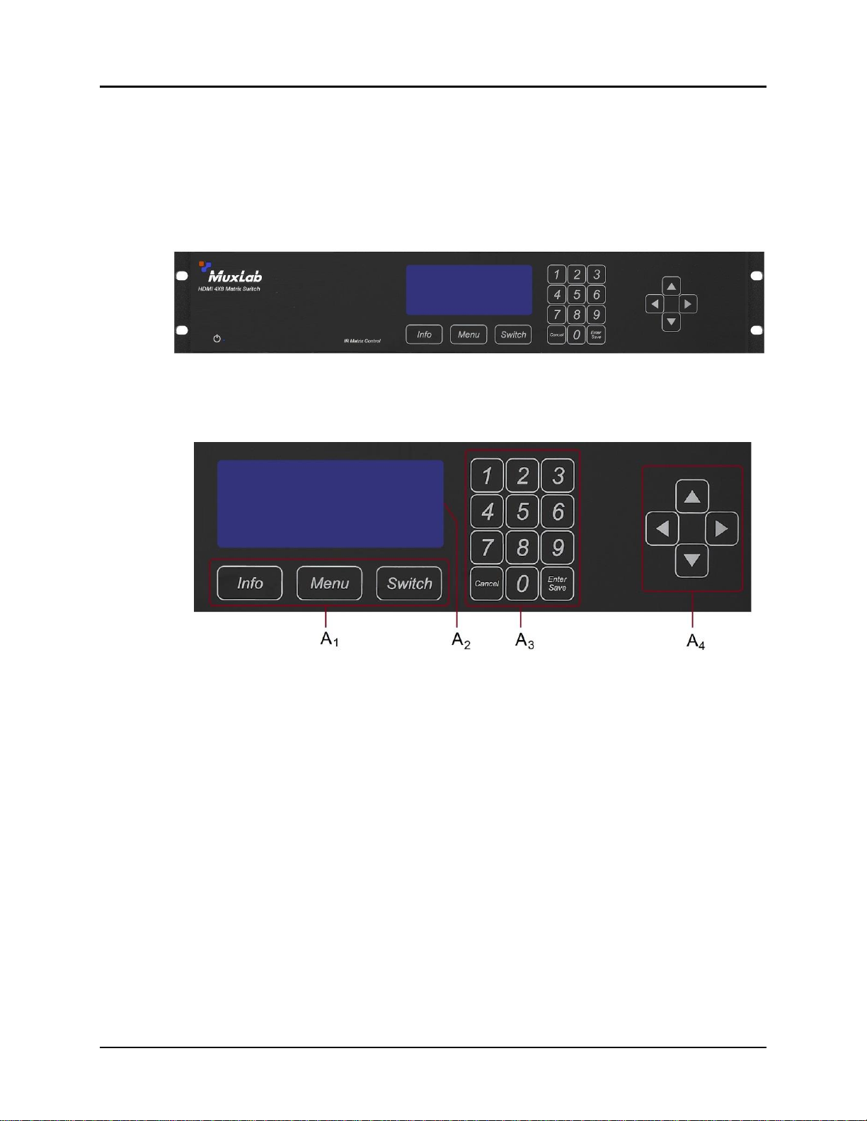
3.2. Product Overview ....................................................................................................................8
3.3. Pre-Installation Checklist.......................................................................................................10
3.4. Physical Installation...............................................................................................................11
3.5. Installation Procedure ............................................................................................................12
3.6. Manual Control......................................................................................................................15
3.7. Remote Control of Matrix Switch..........................................................................................24
3.8. Remote Control of Sources and Displays ..............................................................................25
3.9. EDID and DIP Switch Settings..............................................................................................26
3.10. Port Control Operation...........................................................................................................27
3.11. USB Driver Setup .................................................................................................................. 28
3.12. Ethernet Web Interface ..........................................................................................................31
4. Troubleshooting .......................................................................................................................41
5. Appendix...................................................................................................................................42
A. ASCII Command Set .............................................................................................................42
B. IP Control Commands............................................................................................................55
C. Infrared Remote Control Codes.............................................................................................60
6. Product Warranty Policy........................................................................................................61

© MuxLab Inc. HDMI 4x8 Matrix Switch, HDBT, PoE Installation Guide
Page 4
1.
Overview
1.1.
Description
The MuxLab HDMI 4x8 Matrix Switch, HDBT, PoE (500418-POE) allows 4 HDMI
sources to be switched/distributed to up to 8 remote displays via unshielded twisted
pair (UTP) or shielded twisted pair (STP) cables for cost-efficient connectivity.
Remote displays can be connected up to 230 feet (70 meters) @ 1080p Deep Color via
Cat 5e/6 UTP/STP cables. The Matrix Switch works in conjunction with MuxLab’s
HDMI Receiver (500454-RX or 500454-POE-RX).
Figure 1: System Overview
Applications include commercial and residential AV systems, classroom projector
systems, digital signage, boardroom systems, multi-room systems, classroom training,
retail systems, collaborative PC systems, and medical information systems.

© MuxLab Inc. HDMI 4x8 Matrix Switch, HDBT, PoE Installation Guide
Page 5
1.2.
Features
Single modular RJ45 jacks
UTP/STP extension for 1080p Deep Color up to 230 feet (70 meters) via Cat 5e/6
UTP/STP cables
HDMI 3D support
Seamless integration with MuxLab’s HDMI Receiver (500454-RX or 500454-POE-
RX)
HDMI input supported with resolution up to 1080p
HDBaseT supported output
Configurable EDID settings
Web interface
RS232 and USB CDC control
Firmware is field upgradable
Touch pad on front panel for manual control
Device control over HTTP protocol
2U rackmount unit

© MuxLab Inc. HDMI 4x8 Matrix Switch, HDBT, PoE Installation Guide
Page 6
2.
Technical Specifications
4x8 Matrix Switch, HDBT, PoE
Environment
HDMI 1.4A 3D Support
Devices
LCD and Plasma TVs, DVD and Blu-Ray players, monitors, projectors, PCs, laptops,
home theatre systems, home theater PCs, game consoles.
Transmission
Transparent to the user
Input
Four (4) HDMI and eight (8) IR Sensor (3.5 mm stereo)
Output
Eight (8) HDBaseT (RJ45) and four (4) IR Emitter (3.5 mm mono)
Connectivity
Ethernet LAN (RJ45), USB (Type B) and RS232 (DB9)
Maximum Distance
UTP/STP Cat 5e/6 output port: 230 feet (70 meters)
Cables
Cat 5e/6 UTP/STP cables (or better) required for HDBaseT port
Power
100-240 VAC 50/60Hz, 0.72 A
Matrix Switching Time
3 seconds (maximum)
LED Diagnostics
Power (Blue)
LAN (Link (Green) and Activity (Yellow))
Temperature
Operating: 0ºC to 40ºC
Storage: –20ºC to 85ºC
Humidity: Up to 95% non-condensing
Dimensions
2U Rack Mountable: 19 x 13.6 x 3.5 in (483 x 345 x 88 mm)
Accessories Included
1 IR Sensor, 4 IR Emitters, Remote, USB Cable, RS232 Cable
Shipping Weight
21.6 lbs (9.8 kg)
Regulatory
FCC, CE, RoHS, WEEE
Warranty
Two (2) years
Order Information
500418-POE-US (UPC: 627699014185) HDMI 4x8 Matrix Switch, HDBT
500418-POE-UK (UPC: 627699914188) HDMI 4x8 Matrix Switch, HDBT
500418-POE-EU (UPC: 627699814181) HDMI 4x8 Matrix Switch, HDBT
Table 1: Technical Specifications

© MuxLab Inc. HDMI 4x8 Matrix Switch, HDBT, PoE Installation Guide
Page 7
3.
Installation Procedure
3.1.
Part List
The HDMI 4x8 Matrix Switch, HDBT, PoE (500418-POE) comes with the following
parts:
• Base unit
• Four (4) IR Emitters
• One (1) IR Sensor
• Two (2) Brackets with screws
• Power Cord (US, EU or UK)
• One (1) USB Type A - Type B Cable
• One (1) RS232 Cable
• One (1) Infrared remote
• One (1) Quick Reference Sheet
Please verify that all parts are present before proceeding.

© MuxLab Inc. HDMI 4x8 Matrix Switch, HDBT, PoE Installation Guide
Page 8
3.2.
Product Overview
The external connections and connection indicators of the HDMI 4x8 Matrix Switch,
HDBT, PoE are detailed in Figure 2 and Figure 3. Please familiarize yourself with
them before installing the unit.
Figure 2: Front Panel
Figure 3: Front Panel Controls
A1= Control Buttons
A2= LED Display
A3= Numeric Keypad
A4= Navigational Arrows

© MuxLab Inc. HDMI 4x8 Matrix Switch, HDBT, PoE Installation Guide
Page 9
Figure 4: Back Panel
Figure 5: Back Panel, Right Side Details
B1= Serial Port
B2= USB Port
B3 = LAN Port
B4 = IR Sensor Extender
B5 = EDID Settings
B6 = IR Emitters

© MuxLab Inc. HDMI 4x8 Matrix Switch, HDBT, PoE Installation Guide
Page 10
3.3.
Pre-Installation Checklist
The HDMI 4x8 Matrix Switch, HDBT, PoE provides a centralized HDMI switching
center via UTP/STP cables.
1. The Matrix Switch is used in conjunction with MuxLab’s UTP/STP HDMI
Receivers (500454-RX or 500454-POE-RX).
2. The Matrix Switch is typically installed in a remote telecom room and is connected
to multiple video sources and display devices via Cat 5e/6 UTP/STP or HDMI
cables. A MuxLab Receiver is installed at each display to support the connection
to the Matrix Switch via a Cat 5e/6 cable.

© MuxLab Inc. HDMI 4x8 Matrix Switch, HDBT, PoE Installation Guide
Page 11
3.4.
Physical Installation
MuxLab’s HDMI 4x8 Matrix Switch, HDBT, PoE comes with mounting brackets for
standard 19” rack mounting. Select the final destination for the product and install the
unit using standard rack-mount screws (Figure 6).
Figure 6: Setup for Rackmount Installation
For set-top installation, the side mounting brackets may be removed, and the included
rubber feet placed on the bottom of the unit. When removing the mounting brackets,
be careful to keep and reinstall the screws on each side of the unit (Figure 7).
Figure 7: Setup for Set-top Installation

© MuxLab Inc. HDMI 4x8 Matrix Switch, HDBT, PoE Installation Guide
Page 12
3.5.
Installation Procedure
In order to install the HDMI 4x8 Matrix Switch, HDBT,PoE, please follow the steps
below:
1. Place the Matrix Switch in its final location (see Section 3.4 Physical Installation).
2. Ensure that power is OFF on all sources and displays.
3. Using HDMI cables (not included), connect each source to an HDMI IN port on
the back panel of the Matrix Switch.
4. Ensure that one MuxLab Receiver is connected to each display using an HDMI
cable (not included). For more information, refer to MuxLab’s 500454 Quick
Installation Guide.
5. Using Cat 5e/6 UTP/STP cables (not included) connect each MuxLab Receiver to
an HDBT OUT port on the back panel of the Matrix Switch.
6. OPTIONAL:
•Using an RS232 or USB cable, connect a computer to the corresponding port
on the back panel of the Matrix Switch.
•Using an Ethernet cable, connect the Matrix Switch to the local area network.
•Connect an RS232 cable (not included) between the RS232 port on the
MuxLab Receiver and the RS232 port on the display.
•Connect IR sensors and emitters as needed. For more information, refer to
Figures 5 and 6. NOTE: IR Sensor cables are equipped with a 3.5 mm stereo
jack, and IR Emitter cables are equipped with a 3.5 mm mono jack.
7. Power up the MuxLab Receivers and HDMI equipment.
8. Plug the power cord into an AC power outlet and turn on the power by using the
Power Switch located on the back of the unit. If power is present, the blue power
LED will be illuminated.
9. Ensure that the source and appropriate display LEDs are ON. Images should
appear on the displays within 10 seconds. For signal or image quality problems,
refer to Section 4 Troubleshooting.
10. Figures 8 and 9 show some typical configurations.
The Matrix Switch is now ready to use. See Section 3.7 Manual Control for
instructions on usage.

© MuxLab Inc. HDMI 4x8 Matrix Switch, HDBT, PoE Installation Guide
Page 13
Figure 8: Typical Configuration (I)

© MuxLab Inc. HDMI 4x8 Matrix Switch, HDBT, PoE Installation Guide
Page 14
Figure 9: Typical Configuration (II)

© MuxLab Inc. HDMI 4x8 Matrix Switch, HDBT, PoE Installation Guide
Page 15
3.6.
Manual Control
The HDMI 4x8 Matrix Switch, HDBT, PoE may be controlled manually by using the
controls located on the front panel.
Navigating the manual control menu is performed by using the ‘Info’, ‘Menu’, and
‘Switch’buttons located on the front panel, just below the display, as well as the
numeric keypad and arrows located to the right of the display. (NOTE: The ‘Cancel’
button on the numeric keypad also returns the user to the previous screen.)
Figure 10 illustrates the navigational layout of the manual control menu. Specific
menu screens (depicted by boxes) are described on the following pages.
Figure 10: Manual Control Navigation

© MuxLab Inc. HDMI 4x8 Matrix Switch, HDBT, PoE Installation Guide
Page 16
Startup
The Startup screen is the first screen to appear once the Multimedia 4x8 Matrix Switch
is powered up. It displays the MuxLab logo and product name.
Information
The information screen is reached by pressing the Info button. It displays the name of
the device at top, followed by the IP and Mac addresses, device status, and firmware
version.
Main Menu
The Main Menu screen is reached by pressing the Menu button. It contains four
options:
• Switch
• Presets
• Diagnostics
• Settings
By default, the Switch option is highlighted when the Main Menu screen first displays.

© MuxLab Inc. HDMI 4x8 Matrix Switch, HDBT, PoE Installation Guide
Page 17
NOTE: If password protection is on, pressing the Menu button from the Startup or
Information screens will prompt the Password screen to appear. The user must then
enter the correct password in order to reach the Main Menu screen.
Switch
The Switch screen by either pressing the Switch button, or by highlighting the Switch
entry in the Main Menu screen and pressing the Enter/Save button on the numeric
keypad.
The Switch screen contains four options:
• Connect a source to a display by number
• Connect a source to a display by name
• Connect all displays to a source
• Disconnect all displays from a source
By default, the top-most option is highlighted when the Switch screen first displays.
NOTE: If password protection is on, pressing the Switch button from the Startup or
Information screens will prompt the Password screen to appear. The user must then
enter the correct password in order to reach the Switch screen.

© MuxLab Inc. HDMI 4x8 Matrix Switch, HDBT, PoE Installation Guide
Page 18
Presets
The Presets screen allows the user to select and apply a pre-existing preset (specific
mapping of connections between sources and displays), or to save existing
connections as a preset.
Diagnostic
The Diagnostic screen displays four operating conditions:
• Internal device temperature
• Voltage status
• Fans status
• Existence of alerts
Settings
The Settings screen allows the user to choose which category of settings to change:
• Network
• DHCP
• Password
• RS232

© MuxLab Inc. HDMI 4x8 Matrix Switch, HDBT, PoE Installation Guide
Page 19
Network
The Network Settings screen allows the user to change the settings of the network:
• IP Address
• Mask Address
• Gateway Address
The user navigates the Network Settings screen using the arrow keys, and enters
information using the numeric keypad.
NOTE: In order to access the Network Settings screen, DHCP must be disabled (see
below). If DHCP is not disabled, the following screen will appear:
DHCP
The DHCP screen allows the user to set the state of the DHCP (Dynamic Host
Configuration Protocol) to ON or OFF.

© MuxLab Inc. HDMI 4x8 Matrix Switch, HDBT, PoE Installation Guide
Page 20
Password
The Password screen allows the user to set password protection on the system to ON
or OFF, as well as to change the password (numeric characters only).
RS232
The RS232 screen allows the user to modify the baud rate, data bits, stop bit, and
parity settings of the device.
Connect Source to Displays
The Connect Source to Displays screen allows the user to select which source to
connect to which displays(s). The user selects the source and displays by their
designated number.
This manual suits for next models
2
Table of contents
Other MuxLab Matrix Switcher manuals

MuxLab
MuxLab 500415 User manual

MuxLab
MuxLab 500412 User manual

MuxLab
MuxLab PRODIGITAL 500442 User manual

MuxLab
MuxLab 500412-V2 User manual

MuxLab
MuxLab 500416-POE-US User manual

MuxLab
MuxLab 100508 User manual

MuxLab
MuxLab 500418-POE User manual

MuxLab
MuxLab 500444 User manual

MuxLab
MuxLab 100508 User manual

MuxLab
MuxLab 500210 User manual
Popular Matrix Switcher manuals by other brands

Vanco
Vanco VPW-280799 product manual

Shinybow USA
Shinybow USA SB-3877 instruction manual

Matrix Switch Corporation
Matrix Switch Corporation MSC-HD81AAS product manual

Kramer
Kramer XL 1208V Specifications

GoMax Electronics
GoMax Electronics MA-5588H user manual

Shinybow USA
Shinybow USA SB-8188TB instruction manual