AccessZone ®
GC1000/GC3000/GC4000 Series
Installation Manual
All information is subject to change ithout notice. All other products and brand names are registered trademarks of their respective companies 2012-05-24 US 2.07
Copyright © 2005-2012 All rights reserved MVC-Data ApS Skalhuse 5 9240 Nibe Denmark Web
.mvc-data.com E-mail
[email protected] Phone +45 25 12 84 02
6/20
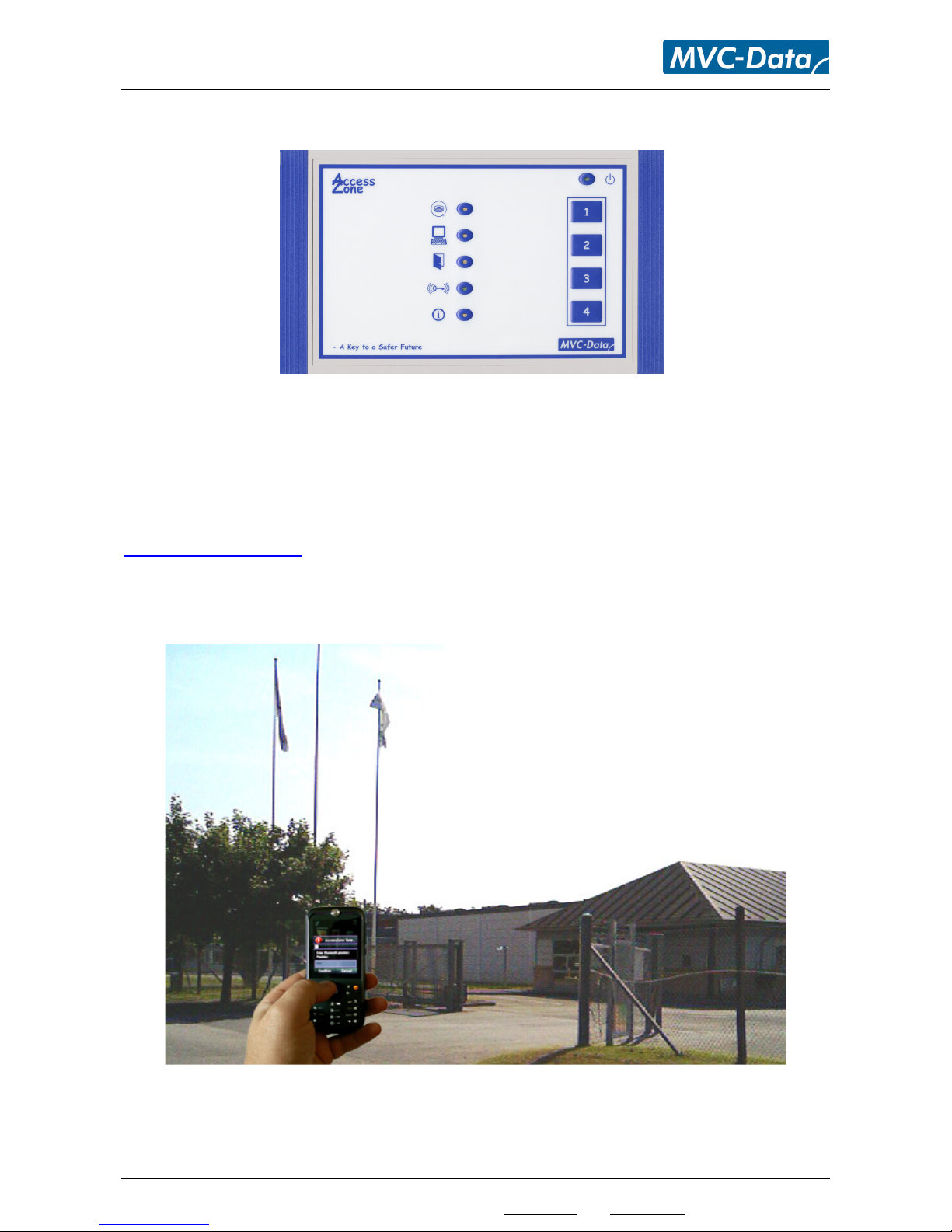
4Mounting
The GC1000/GC3000/GC4000 syste can be ounted on any none metallic
1)
plane surfaces if
using internal antenna. Else any plane surface will do.
The syste can be installed indoor or outdoor. It is advised to install the unit on the secured side
to prevent ta pering and vandalis . The radio waves can penetrate ost none etallic walls so it
is safer to install it on the inner side of a wall.
A typical installation is close to the door/gate in the sa e height as the user will wear the obile
phone or other Bluetooth equipped device. However, it is possible to ake a hidden installation
under none etallic ceilings due to the use of radio waves
2)
. The trans it power and detections
ay need adjust ent to co pensate for the chosen installation. Please see the “AccessZone
PcManagement User Manual” for instruction on how to use and configure the syste .
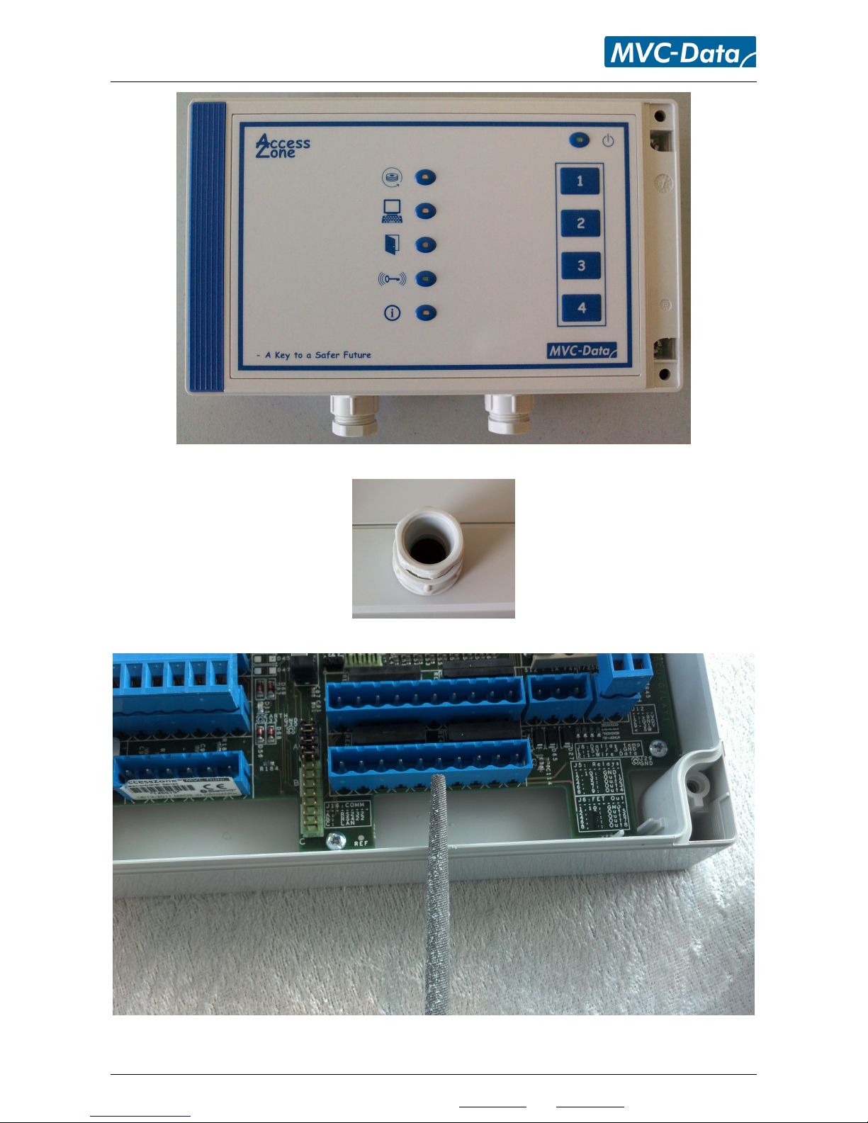
4.1 Box modification
To get the wires into the closed box you have to ake one or ore holes into the box. The
following possibilities should be considered:
1. Outdoor place ent: Here extra care ust be taken so that oisture can’t get into the box.
By itself the box is IP65 co pliant. So please use PG9 or PG11 accessories and the sa e
nu ber as the nu ber of cables needed.
2. Indoor place ent: Here hidden cabling trough the botto could be considered with holes
fitting the needed cables.
3. Indoor place ent: When practicality is weighed higher than aesthetics then a si ple half
hole cut out, with a file, in the botto half could be considered.
Caution
Please observe ordinary ESD precautions hen handling the box, print and ires.
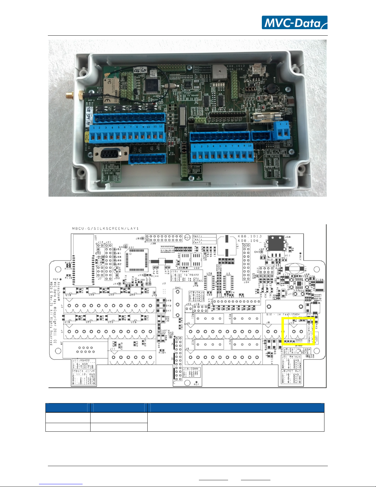
4.2 Adding ater proof fittings
To ake the box water proof you have to carefully ount 1 or 2 PG11 or PG9 fittings. This can be
done like on the below picture. Please be aware of the size of the inside nut of the PG11 / PG9
fitting.
Caution
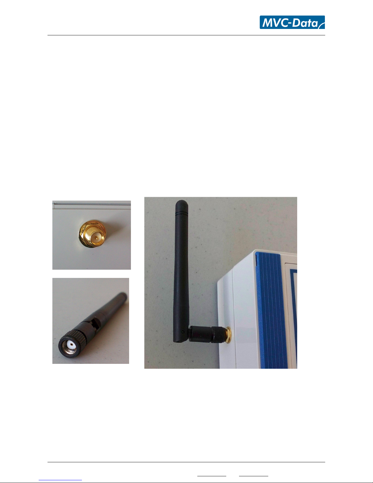
1)
Metallic surfaces will reflect/prevent radiation of the radio waves (2,4GHz) used by Bluetooth.
Keep the antenna in a good distance from any metallic surfaces. This means at least 4cm.
2)
Status LED’s are not visible