3
NL
M1.1.BK500.NLFREN 20072018
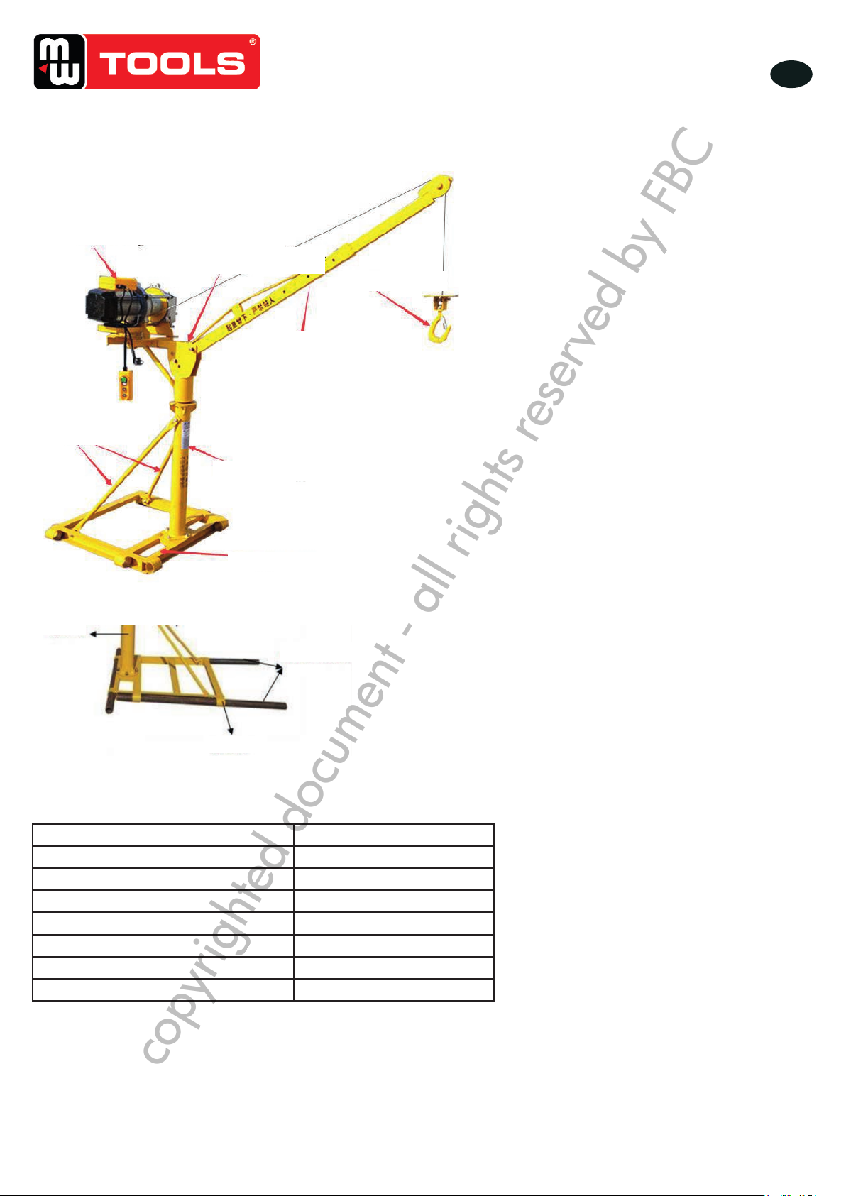
3 Installatie
1. Breng eerst alle onderdelen naar de werkruimte en bereid drie stalen buizen (lengte 3 tot 5 m, diameter 48 mm, dikte
3 mm), een contragewicht van meer dan 600 kg, tangen, schroevendraaiers, een hamer, een schroefsleutel met een
maximale opening van 27 mm en andere gereedschappen.
2. Assembleer de basis en de kolom met schroeven (de schroeven moeten nog niet vastgedraaid worden).
3. Gebruik de staven om de kolom en de basis te assembleren, en kies het gaten in de staaf en in de basis, zodat de kolom
loodrecht op de basis staat.
4. Het roterende deel van de huls is op de rotatieas bovenaan de kolom gemonteerd, om de rotatiefexibiliteit en de
gevoeligheid van het positioneringsmechanisme te garanderen.
5. Verbind het bevestigingsgat aan het uiteinde van de draagarm met het bevestigingsgat van de roterende arm, en pas
vervolgens de hoek van de pen aan, zodat de helling van de draagarm de juiste hoek bereikt.
6. Pas de uitschuiengte van de telescopische arm aan, afhankelijk van het uit te voeren werk.
7. Neem de motor, installeer de haak, zet de stroom aan, druk op de bedieningshendel om te controleren of de motor
normaal werkt.
8. Plaats het midden van de kabelschijf in overeenstemming met het midden van de motorzitting. De kabelschijf moet
loodrecht op de draagarm staan. Gebruik vervolgens de bevestigingsschroeven om het torentje te bevestigen.
9. Wanneer de motor ingeschakeld is, druk op de schakelaar om de juiste kabellengte af te wikkelen, en voer de kabel over
de kabelschijf en op de draagarm.
10. Verplaats de kraan op de werkruimte, zet 3 stalen buizen aan de voorkant van de basis in, links en rechts, plaats het
contragewicht op de stalenbuis aan de achterkant van de kraan, om de stabiliteit ervan te garanderen.
11. Bedien de kraan en ontlast de hijshaak. Bij het eerste gebruik moet de maximale belasting 30% van de nominale
capaciteit bereiken. Nadat u de kraan 3 keer met een lage belasting heeft bediend, verhoog de belasting geleidelijk. Het
is verboden om de nominale capaciteit van de kraan te overschrijden.
12. De bediener moet veiligheidsriemen gebruiken, een helm dragen en andere veiligheidsvoorzieningen, om ongevallen te
voorkomen.
13. Houd tijdens het gebruik van de kraan mensen uit de buurt ervan, binnen een straal van 20 meter, om letsels te voorkomen
door vallende voorwerpen.
4 Veiligheidsvoorschriften
• Deze kraan mag niet gebruikt worden om mensen op te hangen, en mag niet overbelast worden.
• Controleer voor ieder gebruik dat alle bevestigingsbouten goed vastzitten, dat de laspunten niet gescheurd of versleten zijn
en dat er geen andere problemen zijn. Onderhoud de kraan op tijd.
• Controleer dat de rem soepel en correct werkt, de steunpunten moeten betrouwbaar zijn.
• Controleer dat de kolom goed verticaal is en dat het chassis stabiel is.
• Het is verboden voor iedereen om onder de kraan te blijven. De arbeiders op het werf moeten op 20 meter van de
hangende voorwerpen blijven.
• De kraan moet door een zware last vastgehouden worden. Het contragewicht moet minstens twee keer zo zwaar zijn als
het op te tillen object.
• Het chassis moet zo gedemonteerd worden, dat het niet valt en slachtoffers maakt.
• De bediener moet vertrouwd zijn met de voorzorgmaatregelen voor het gebruik van de kraan. Draag een helm bij het
gebruik van de kraan, en gebruik veiligheidsriemen, die u aan betrouwbare bevestigingspunten bevestigd. Zorg ervoor dat
de riemen niet aan het chassis bevestigd wordt, om letsels te voorkomen als een persoon en het chassis tegelijkertijd vallen.
In geval van niet-conforme werking is de gebruiker de enige verantwoordelijke voor de gevolgen.
• Overschrijd het maximale hijsvermogen en de in de technische gegevens gespeciceerde parameters niet. In geval van
overbelasting is de fabrikant niet verantwoordelijk.
• De kabel mag niet minder dan 4 omwentelingen rond de haspel hebben. Controleer de kabel op beschadigingen,
breuken, gebroken draden, pluizen, gebrek aan vet of andere defecten. Vervang de kabel indien nodig.
• Controleer de elektrische componenten vaak en verwijder de stof tijdig, vervang defecte onderdelen, let op de veiligheid
van het elektrische systeem, om elektrische schokken, lekkages, ... te voorkomen.
• De installatie van een differentieelbeveiliging is noodzakelijk.
• De voedingskabel moet een doorsnede van meer dan 2,5 mm² hebben.
• De ballastbuis moet voldoen aan Φ 48, met een dikte van 3 mm of meer.
copyrighted document - all rights reserved by FBC