M1.2.MRP300.NLFREN 15112018
4
NL
Veiligheidsvoorschriften
1. Lees en begrijp de handleiding en de op de machine aangebrachte labels. Leer het toepassingsgebied van de machine,
alsook de grenswaarden en mogelijke risico’s van de machine.
2. Verzeker u ervan, dat u de bedieningselementen en hun werking goed kent. Weet hoe de machine snel te stoppen en de
bedieningen uit te schakelen.
3. Zorg ervoor, alle instructies en veiligheidsvoorschriften te begrijpen. Gebruik de machine niet zolang u de werking ervan
niet goed kent.
4. De uitlaatgassen zijn schadelijk. Als de machine binnenshuis gebruikt wordt, zorg voor een goede ventilatie.
5. Gebruik de machine niet in een explosieve of ontvlambare atmosfeer.
6. Loop met de machine, ren niet.
7. Blijf waakzaam. Gebruik de machine niet als u onder de invloed bent van alcohol, drugs of geneesmiddelen die uw
concentratievermogen kunnen verminderen.
8. Draag gepaste kledij. Draag laarzen en handschoenen. Draag geen loszittende kleren.
9. Gebruik lichamelijke beschermingen. Draag steeds een veiligheidsbril en een gehoorbescherming.
10. Controleer de machine voor het begin van het werk. Zorg ervoor, dat de beschermingen goed op hun plaats zitten en
bedrijfsklaar zijn. Zorg ervoor dat alle bouten en moeren goed aangedraaid zijn.
11. Gebruik de machine niet als er een brandstof lekkage is, of als er een defect onderdeel is. Vervang de defecte of
ontbrekende onderdelen voor het gebruik.
12. Controleer altijd dat alle sleutels weg van de machine werden genomen alvorens deze in te schakelen.
13. Houd een goede balans. Werk nooit met de machine met blote voeten of met sandalen. Draag veiligheidshandschoenen
om je voeten te beschermen en uitglijden te voorkomen.
14. Schakel de machine uit om benzine te tanken of af te tappen. Wacht tot alle onderdelen afgekoeld zijn en maak zeker dat
er geen ontstekingsbronnen zoals vonken of vlammen in de buurt van de machine zijn. Houd de brandstof steeds weg van
ontstekingsbronnen.
15. Als tijdens het tanken gemorste brandstof voordoet, gebruik een droog doek om af te vegen en verplaats de machine
tenminste 5 m ver van het verontreinigde gebied.
16. Controleer de oliepeil voor het begin van het werk. Schakel de machine niet in als de oliepeil laag is.
17. Verander de instelling van de snelheidscontrole nooit. Een te hoge snelheid is gevaarlijk voor de gebruiker.
18. Laat de handgreep nooit los. Het risico neemt toe wanneer de machine niet langer geleid wordt.
19. De machine mag uitsluitend door volwassenen gebruikt worden. Houd de machine buiten bereik van kinderen.
20. Reparaties, onderhoud en instellingen moeten door gekwaliceerd personeel uitgevoerd worden.
21. Wanneer de machine niet meer bruikbaar is, verwijder deze op een milieuvriendelijk wijze. Breng deze naar uw verdeler
terug, deze zal voor een correcte afvalverwerking zorgen.
22. Vul nooit te veel brandstof in. Het brandstofniveau mag de markering op de tanklter niet overschrijden.
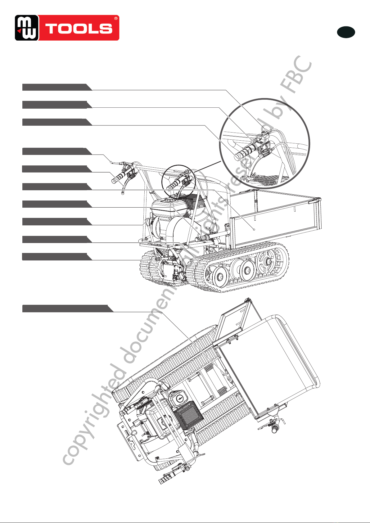
2 Specicaties en omschrijving van de machine
Model MRP300
Motor 6,5 pk / 196 cc
Versnellingen 3 vooruit + 1 achteruit
Laadcapaciteit 300 kg
Lengte laadbak 910 mm
Breedte laadbak 600 mm
Diepte laadbak 204 mm
Breedte rupsen 180 mm
Inhoud olietank 0,6 l
Inhoud benzinetank 3 l
Autonomie 4 h
Geluidsniveau 101 dB(A)
Netto gewicht 178 kg
copyrighted document - all rights reserved by FBC