8
FR
M1.2.PTLK1-PTLK2.NLFREN 01102019
Étape 2
Attachez chaque montant vertical intérieur à la traverse (n° 19). Fixez avec les 8
boulons (n° 1), rondelles (n° 2), rondelles à ressort (n° 3) et écrous (n° 4).
Étape 3
Fixez les 4 roues pivotantes avec frein (n° 27) à la base (n° 25). Appliquez de la
graisse sur chaque roulement.
Étape 4
Attachez chaque poteau vertical extérieur (n° 23) à chaque base (n° 26), en vous
assurant que les fentes des deux côtés du poteau vertical extérieur font face à la
direction des roues. Par le haut, insérez deux boulons (n° 14) à travers la base
du poteau vertical extérieur et la base (n° 26). Glissez la rondelle (n° 2) et la
rondelle à ressort (n° 3) et xez le tout avec l’écrou (n° 4).
Étape 5
Attachez les deux tubes de (n° 22) à chaque poteau vertical extérieur (n° 23).
Insérez le boulon (n° 5) à travers le haut du tube de support et à travers l’œillet.
Glissez une rondelle (n° 6) et une rondelle à ressort (n° 7) et xez avec l’écrou (n°
8).
Attachez l’autre extrémité du tube de support à la base avec de boulons, des
rondelles, des rondelles à ressort et des écrous. Répétez l’opération pour les
quatre tubes de support.
Étape 6
Insérez le poteau vertical intérieur (n° 21) dans le poteau vertical extérieur (n°
23). Insérez une des goupilles avec chaîne (n° 18) à travers la fente et le trou du
poteau vertical intérieur, de manière à ce qu’elle traverse jusqu’à l’autre goupille.
Fixez la poignée (n° 24) au support sur le côté du poteau vertical extérieur,
insérez le boulon (n° 10) depuis l’intérieur, glissez la rondelle (n° 14), la rondelle
à ressort (n° 15) et xez avec l’écrou (n° 11). Assurez-vous que les deux crochets
de la poignée tiennent les deux extrémités de la goupille (n° 18). Répétez
l’opération pour l’autre poteau.
Étape 7
Fixez fermement tous les boulons et écrous, et assurez-vous que l’assemblage soit bien serré et sûr.
Étape 8
Testez la grue selon le mode d’emploi et les normes ANSI/ASME B30.17.
Page 7 of 13
Assemble the crane loosely until the entire assembly is complete. Make certain that you have a large,
clean, and uncluttered area for assembly. As the crane is large and heavy, you may have to lay out
the different parts on their sides, and tighten and erect the entire assembly once complete.
Step 1) Attach two Plates (#20) from two sides to the one end of the Crossbeam (#19). Secure
with the four Bolts (#1), Washers (#2), Spring Washers (#3), and Nuts (#4). Repeat for the
other end.
Step 2) Attach each Inner Vertical Post Assembly to the Crossbeam (#19). Secure with the 8 Bolts
(#1), Washers (#2), Spring Washers (#3), and Nuts (#4)
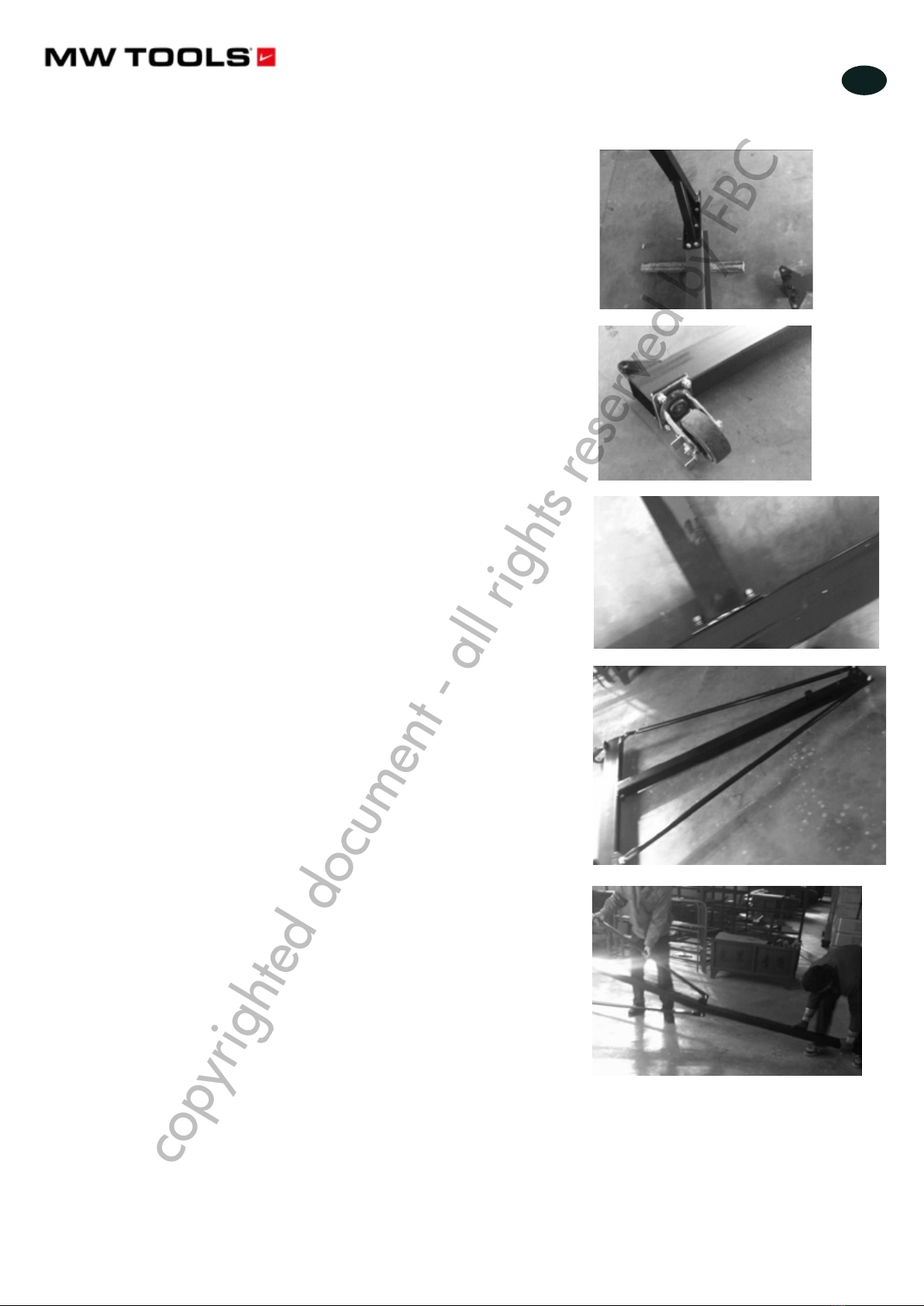
Step 3) Attach the four Swivel Casters with Brake (#27) to the Base Assembly (#26). Apply grease
to the zerk in each Caster.
Step 4) Attach each Outer Vertical Post Assembly (#24) to each Base Assembly (#26), making
certain that the slot at two sides of the Outer Vertical Post Assembly are facing the
Casters’direction. From the top, insert two (2) Bolts (#14) through the base of the Outer
Vertical Post Assembly, and into the Base Assembly (#26). Slip on the Washer (#2) and
Spring Washer (#3) and secure by tightening the Nuts (#4).
Page 7 of 13
Assemble the crane loosely until the entire assembly is complete. Make certain that you have a large,
clean, and uncluttered area for assembly. As the crane is large and heavy, you may have to lay out
the different parts on their sides, and tighten and erect the entire assembly once complete.
Step 1) Attach two Plates (#20) from two sides to the one end of the Crossbeam (#19). Secure
with the four Bolts (#1), Washers (#2), Spring Washers (#3), and Nuts (#4). Repeat for the
other end.
Step 2) Attach each Inner Vertical Post Assembly to the Crossbeam (#19). Secure with the 8 Bolts
(#1), Washers (#2), Spring Washers (#3), and Nuts (#4)
Step 3) Attach the four Swivel Casters with Brake (#27) to the Base Assembly (#26). Apply grease
to the zerk in each Caster.
Step 4) Attach each Outer Vertical Post Assembly (#24) to each Base Assembly (#26), making
certain that the slot at two sides of the Outer Vertical Post Assembly are facing the
Casters’direction. From the top, insert two (2) Bolts (#14) through the base of the Outer
Vertical Post Assembly, and into the Base Assembly (#26). Slip on the Washer (#2) and
Spring Washer (#3) and secure by tightening the Nuts (#4).
Page 8 of 13
Step 5) Attach two Support Tubes (#22) to each Outer Vertical Post Assembly (#23). Insert the
Bolt (#5) through the top of the Support Tube, and through the Eyelet. Slip on a Washer
(#6) and Spring Washer (#7) and secure with the Nut (#8). Attach the other end of the
Support Tube to the Base Assembly with Bolts, Washers, Spring Washers, and Nuts.
Repeat for all four Support Tubes.
Step 6) Insert the Inner Vertical Post (#21) into the Outer Vertical Post (#23). Insert one (1) Pin of
the Pins with Chain (part #18) through the slot and the Inner Vertical Post Hole so that it
goes all the way through to the other pin. Attach the Handle (#24) to the bracket on the
side of Outer Vertical Post, insert the Bolt (#10) from the inside, slip on the Washer (#14)
and Spring Washer (#15) and secure with the Nut (#11). Make sure the two (2) hooks of
the Handle hold the two ends of the Pin (#18). Repeat for the other Post Assembly.
Step 7) Tighten all the Bolts and Nuts securely and make certain that the entire assembly is tight
and secure.
Step 8) Test the crane according to manual and ANSI/ASME B30.17 standards.
Operating Instructions
Never force the crane or attachment to do the work of a larger industrial tool. It is designed to do the
job correctly and safely in the manner for which it was intended.
Step 1) Move the crane so that it is directly above the item to be lifted.
Step 2) Securely fasten the item to the crane with the appropriate trolley or hoist.
copyrighted document - all rights reserved by FBC