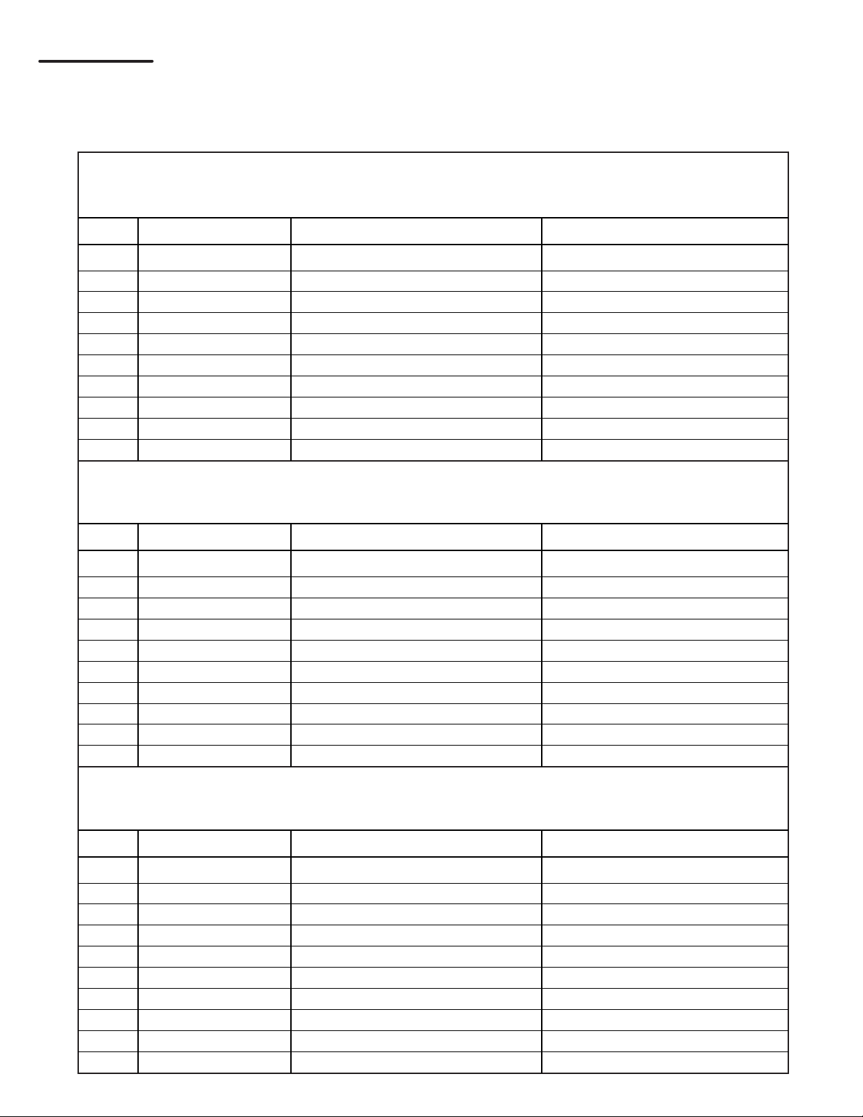
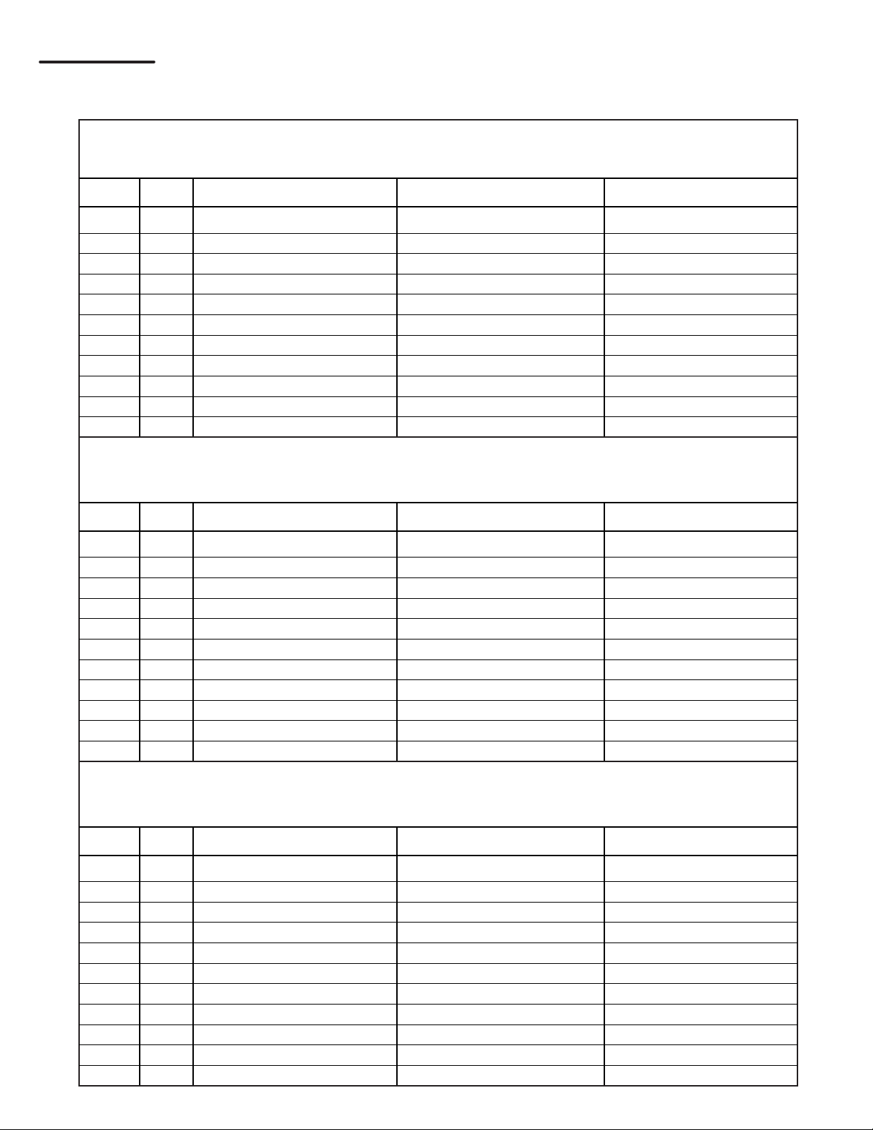
MWBS Library Bed BC-2 User manual

Fits all Single/Twin, Double/Full, Queen Beds
[Model #BC-2: Sliding Bookcase]
Cabinet Cut List & Assembly Instructions
Toll Free:
Phone:
Fax:
877-887-1717
773-248-5188
773-281-6430
© 2010 Murphy WallBed Systems Inc.
2650 N. Lakeview #308
Chicago, IL 60614
The Library Bed ™
Let’s build a Wallbed together!
Issue:032311

2.
Project Start-Up
Steps to Complete Project
Prep. Cut and prepare all wood or laminate cabinet components.
1. Assemble Bed Cabinet
2. Fasten Bed Cabinet to Wall
3. Assemble Side Cabinets, left and right
4. Position and secure Side Cabinets to Bed Cabinet
5. Install Steel Support
6. Install Aluminum Rail Tracks
7. Assemble Sliding Bookcases, left and right
8. Mount Sliding Bookcases
Familiarize yourself with all of the components in the Library Bed cartons and
thoroughly study this manual so you may plan the steps required to complete this
project.
Study all illustrations and plan drawings. Make sure that the space available is
adequate for the specified dimensions of the bed cabinet, both in the open and
closed positions.
Panels should be 3/4” (19mm) ply core. Particle board is acceptable but with
more attention given to assembly procedures and handling. This is discussed
further in this manual.
Handles to pull the bed open are not provided. Select these from your local deco-
rative hardware supplier. Have them on site at the time of assembly.
Check to be sure that all items are available
Steel Bed Frame and Mechanism
Cabinet Components and Hardware
Necessary Tools
BC-2 SLIDING Single Double Queen
Cabinet Size (D,W,H) 24” x 86“ x 88” 24“ x 115” x 88“ 24” x 127“ x 93”
(638 x 2184 x 2235) (638 x 2921 x 2235) (638 x 3226 x 2362)
Projection from Wall (P) 86 1/8” (2188) 86 1/8” (2188) 91 1/8” (2315)
Mattress Size 39“ x 75” (991 x 1905) 54“ x 75” (1372 x 1905) 60“ x 80” (1524 x 2032)
FOOTPRINT DIMENSIONS: Cabinet Sizes & Projection from Wall
Dimensions in ( ) are mm.
All beds accept mattress thickness up to 12 inches.

3.
4-Wheel Nylon Carrier
See pg. 13 for mounting information
*Image is not to scale*
#10 x 3/4” Pan Head Square Screw
See pgs. 8,13,16
(attach AL Rail and Nylon Carriers)
Scale is 1:1
3” x 5/16” Bolt & T-Nut Washer
See pg. 8 (attach steel tube)
Scale is 1:1
#6 x 5/8” Flat Head Phillips Screw
See pg. 14
(attach Bottom Roller Guide}
Scale is 1:1
AL Extrusion/Rubber Bumper
See pg. 10
*Image is not to scale*
Bottom Roller Guide
See pg. 14
*Image is not to scale*
Steel Tube
(0.1 x 1.5 x 1.5 x 64“) / (2.5 x 38 x 38mm x 1.63m)
2 Through Holes
See pg. 9
*Image is not to scale*
AL Rail Extrusion
(L: 63”,1.6m)
See pg. 9
*Image is not to scale*
BC-2 Sliding Bookcase
Hardware Components List

SINGLE/TWIN BED
Numbers in parenthesis ( ) are mm
Cabinet Material: 3/4“ (18) MDF or Plycore
QTY PART WIDTH LENGTH
1 Right Side Panel 16” (406) 85” (2159)
2 Left Side Panel 16” (406) 85” (2159)
3 Front Kick 4 1/2” (114) 41” (1041)
4 Headboard 14 7/8” (378) 41” (1041)
5 Top Facia (2) 3” (76) 41” (1041)
6 Top Panel 16” (406) 41” (1041)
7 Library Top 25 1/8” (638) 42 1/2” (1080)
8 Front Valance 6 1/4” (159) 42 1/2” (1080)
9 Nailer 6 1/4” (159) 45 1/2” (1156)
10 Steel Support 1 1/2” x 1 1/2” (38 x 38) 64” (1626)
DOUBLE/FULL BED
Numbers in parenthesis ( ) are mm
Cabinet Material: 3/4“ (18) MDF or Plycore
QTY PART WIDTH LENGTH
1 Right Side Panel 16” (406) 85” (2159)
2 Left Side Panel 16” (406) 85” (2159)
3 Front Kick 4 1/2” (114) 56” (1422)
4 Headboard 14 7/8” (378) 56” (1422)
5 Top Facia (2) 3” (76) 56” (1422)
6 Top Panel 16” (406) 56” (1422)
7 Library Top 25 1/8” (638) 57 1/2” (1460)
8 Front Valance 6 1/4” (159) 57 1/2” (1460)
9 Nailer 6 1/4” (159) 60 1/2” (1537)
10 Steel Support 1 1/2” x 1 1/2” (38 x 38) 64” (1626)
QUEEN BED
Numbers in parenthesis ( ) are mm
Cabinet Material: 3/4“ (18) MDF or Plycore
QTY PART WIDTH LENGTH
1 Right Side Panel 16” (406) 90” (2286)
2 Left Side Panel 16” (406) 90” (2286)
3 Front Kick 4 1/2” (114) 62” (1575)
4 Headboard 14 7/8” (378) 62” (1575)
5 Top Facia (2) 3” (76) 62” (1575)
6 Top Panel 16” (406) 62” (1575)
7 Library Top 25 1/8” (638) 63 1/2” (1613)
8 Front Valance 6 1/4” (159) 63 1/2” (1613)
9 Nailer 6 1/4” (159) 66 1/2” (1689)
10 Steel Support 1 1/2” x 1 1/2 (38 x 38) 64” (1626) 4.
STEP #1
BED CABINET COMPONENT CUT LIST

Assembly of parts 1-7
are shown below.
1068
9
1
3
2
4
5
7
5.
STEP #1
BED CABINET ASSEMBLY
Assemble parts 1-7. Note that the Top Panel (6) is assembled between Left and Right
Side Panels (1,2). The Library Top (7) is fastened to the top of the whole assembly.
NOTE: Do not assemble parts 8, 9 or 10 at this time.

6.
STEP #2
BED CABINET POSITIONING
Position Bed Cabinet to wall - Loosely attach to studs with #8 x 3” wood screws. Be sure
to locate at least three wall studs for secure attachment.

SINGLE/TWIN BED
Numbers in parenthesis ( ) are mm
#(L) #(R) PART WIDTH LENGTH
11 11 Right Side Panel 16” (406) 85” (2159)
12 12 Left Side Panel 16” (406) 85” (2159)
13 13 Front Kick 3 13/16” (97) 19 3/4” (502)
14 14 Deck 16” (406) 19 3/4” (502)
15 15 Horizontal Partition 16” (406) 19 3/4” (502)
16 16 Adjustable Shelf (3) 15 7/8” (403) 19 3/4” (502)
17 17 Top Facia 3” (76) 19 3/4” (502)
18 18 Top Panel 16” (406) 19 3/4” (502)
19 19 Library Top 25 1/8” (638) 21 1/4” (540)
20 20 Front Valance 6 1/4” (159) 22” (559)
21 21 Side Valance 6 1/4“ (159) 25 1/8” (638)
DOUBLE/FULL BED
Numbers in parenthesis ( ) are mm
#(L) #(R) PART WIDTH LENGTH
11 11 Right Side Panel 16” (406) 85” (2159)
12 12 Left Side Panel 16” (406) 85” (2159)
13 13 Front Kick 3 13/16” (97) 27 1/4” (692)
14 14 Deck 16” (406) 27 1/4” (692)
15 15 Horizontal Partition 16” (406) 27 1/4” (692)
16 16 Adjustable Shelf (3) 15 7/8” (403) 27 1/4” (692)
17 17 Top Facia 3” (76) 27 1/4” (692)
18 18 Top Panel 16” (406) 27 1/4” (692)
19 19 Library Top 25 1/8” (638) 28 3/4” (730)
20 20 Front Valance 6 1/4” (159) 29 1/2” (749)
21 21 Side Valance 6 1/4“ (159) 25 1/8” (638)
QUEEN BED
Numbers in parenthesis ( ) are mm
#(L) #(R) PART WIDTH LENGTH
11 11 Right Side Panel 16” (406) 90” (2286)
12 12 Left Side Panel 16” (406) 90” (2286)
13 13 Front Kick 3 13/16” (97) 30 1/4” (768)
14 14 Deck 16” (406) 30 1/4” (768)
15 15 Horizontal Partition 16” (406) 30 1/4” (768)
16 16 Adjustable Shelf (3) 15 7/8” (403) 30 1/4” (768)
17 17 Top Facia 3” (76) 30 1/4” (768)
18 18 Top Panel 16” (406) 30 1/4” (768)
19 19 Library Top 25 1/8” (638) 31 3/4” (806)
20 20 Front Valance 6 1/4” (159) 32 1/2” (826)
21 21 Side Valance 6 1/4“ (159) 25 1/8” (638) 7.
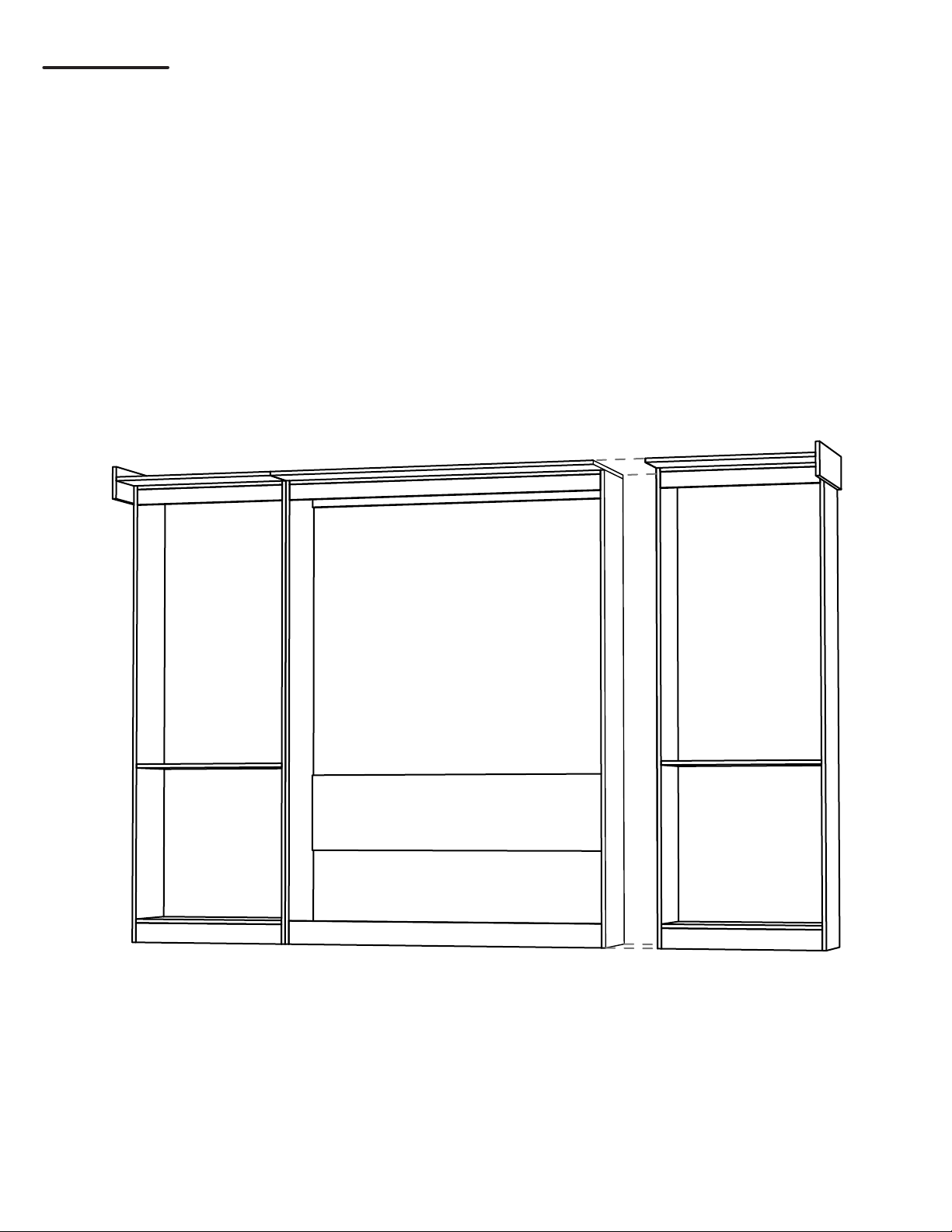
STEP #3
SIDE CABINET COMPONENT CUT LIST; LEFT AND RIGHT

Note: Left and right sides are identical except for their top assemblies (Left shown).
Repeat assembly steps for the Right Side Cabinet.
21 20 19
11
17
18
12
13 14
16
15
8.
2.0” (51)
STEP #3
SIDE CABINET ASSEMBLY
Assemble parts 11, 12, 13, 14, 15, 17, 18, 19 and 21 as shown below.
NOTE: Parts 16 are adjustable shelves and will be added later.
Part 18 mounts between 11 and 12.
Part 20 will be added to assembly later.

9.
STEP #4
SIDE CABINET POSITIONING
Position and secure Left and Right Side Cabinets to Bed Cabinet using #8 x 11/4”
wood screws.
Square and level bed cabinet and left and right side cabinets. Make final secure
attachment through the back of Top Facia (5) of the Bed Cabinet using (3) #8x3” wood
screws, into studs.

10.
14.0”
(356)
2.0”
(51)
10
STEP #5
INSTALL STEEL SUPPORT
Fasten the square 1.5”x1.5” (38 x 38) Steel Support (10) to the top of the assembly
using the provided 3.0” bolts and T-nuts. The Steel Support should be centered on top
of the bed cabinet and bolt holes should be 14.0” (356) from the wall. Use the holes in
the support to guide for drilling.
STEP #6
ATTACH LEFT SIDE ALUMINUM TRACK
Position inside edge of track 2.0” (51mm) from cabinet front as shown below. Right end of
track should be centered with the bed cabinet. The aluminum tracks come as queen size;
use a hacksaw to shorten them both equally to fit single or full size beds.

11.
STEP #6
INSTALL LEFT END RUBBER SAFETY STOP
Slide one rubber safety stop to end of left track in position shown below. Loosely tighten
to track with provided screws, you will tighten later.

SINGLE - SLIDING BOOK CASE
Numbers in parenthesis ( ) are mm
# PART WIDTH LENGTH
22 Right Side Panel 8” (203) 81 7/16” (2069)
23 Left Side Panel 8” (203) 81 7/16” (2069)
24 Front Kick 3” (76) 19 3/4” (502)
25 Deck 7 1/4” (184) 19 3/4” (502)
26 Horizontal Partition 7 1/4” (184) 19 3/4” (502)
27 Adjustable Shelves 7 1/8” (181) 19 3/4” (502)
28 Top Facia 3” (76) 19 3/4” (502)
29 Top Panel 7 1/4” (184) 19 3/4” (502)
30 Back Panel 19 3/4” (502) 81 7/16” (2069)
FULL - SLIDING BOOK CASE
Numbers in parenthesis ( ) are mm
# PART WIDTH LENGTH
22 Right Side Panel 8” (203) 81 7/16” (2069)
23 Left Side Panel 8” (203) 81 7/16” (2069)
24 Front Kick 3” (76) 27 1/4” (692)
25 Deck 7 1/4” (184) 27 1/4” (692)
26 Horizontal Partition 7 1/4” (184) 27 1/4” (692)
27 Adjustable Shelves 7 1/8” (181) 27 1/4” (692)
28 Top Facia 3” (76) 27 1/4” (692)
29 Top Panel 7 1/4” (184) 27 1/4” (692)
30 Back Panel 27 1/4” (692) 81 7/16” (2069)
QUEEN - SLIDING BOOK CASE
Numbers in parenthesis ( ) are mm
QTY PART WIDTH LENGTH
22 Right Side Panel 8” (203) 86 7/16” (2196)
23 Left Side Panel 8” (203) 86 7/16” (2196)
24 Front Kick 3” (76) 30 1/4” (768)
25 Deck 7 1/4” (184) 30 1/4” (768)
26 Horizontal Partition 7 1/4” (184) 30 1/4” (768)
27 Adjustable Shelves 7 1/8” (181) 30 1/4” (768)
28 Top Facia 3” (76) 30 1/4” (768)
29 Top Panel 7 1/4” (184) 30 1/4” (768)
30 Back Panel 30 1/4” (768) 86 7/16” (2196) 12.
STEP #7
SLIDING BOOK CASE COMPONENTS
NOTE: Two of each part are included for the identical left and right sliding cabinet
assemblies.

13.
22
28 29
30
25
24
26
27
23
2 Angle Brackets
Front
STEP #7
SLIDING BOOKCASE VISUAL PART REFERENCE & ASSEMBLY
Assemble Left and Right Sliding Cabinets as shown below. Attach backs with
1 3/4” Wood Screws, from the back side, into 25, 26 and 29 (3 in each shelf).
Fasten 2”x2” Angle Brackets over top back corner of 29 and 30 as shown below using
8x3/4” Flat Head Wood Screws. Brackets are not included.
NOTE: Left and Right Sliding Cabinets are identical and have the same numbered parts.
Do not place the Adjusable Shelves (27) at this time; they will be added later.

Sliding Book Case Top
Nylon Carrier
14.
.375”
(10)
3.5”
(89)
2.125”
(54)
23
29
STEP #7
INSTALL NYLON CARRIERS
Drill 3/8” (10mm) holes in the tops of the Sliding Book Cases as shown below. Screw
Nylon Carriers through the top, into the threaded plates. Do not tighten nuts at this point.

Sliding CabinetSide Cabinet
14
15.
A
DETAIL A
3.5”
(89)
STEP #7
INSTALL SLIDING ROLLERS
Install (2) Sliding Rollers to the back bottom side of each Sliding Cabinet approximately
3.5” (89) up from the bottom of Sliding Cabinet (opposite of the Deck, #14) to the center
of the rollers. More important, be sure that rollers will line up on the Front Toe pieces of
the Left Side, Right Side and Bed Cabinets (If they are too high they will not function
properly).
NOTE: Sliding Book Cases are not on track yet. Image below is only for future reference.

16.
STEP #8
MOUNT SLIDING BOOK CASES
Hang one Sliding Book Case on Left Track. Next, slide on two Rubber Safety Stoppers
back to back but do not secure. Hang the second Sliding Book Case and the last Rubber
Safety Stop. Both Book Cases and all 4 Safety Stops should be on the left Aluminum
Track at this point.
Next, hang right side of Aluminum Track so that it butts up against the left side,
in the center of the Bed Cabinet.

Install all adjustable shelves in cabinets and book cases.
Install Murphy Bed Mechanism.
Attach Front Valances (8,20), and Nailer (9).
17.
Copyright by Murphy WallBed Systems Inc. No part of this publication may be reproduced or
transmitted without permission of the Copyright owner. © 2010 Murphy WallBed Systems Inc.
Using the adjuster bolts on the 4-wheel Nylon Carriers, level and square
the Sliding Book Cases. Tighten the Rubber Safety Stops in their proper
positions.
Table of contents
Other MWBS Indoor Furnishing manuals
Popular Indoor Furnishing manuals by other brands

Songmics
Songmics VASAGLE LWD56/056 quick start guide

Design Within Reach
Design Within Reach Folk 32" Desk Ladder Shelving manual

Steve Silver
Steve Silver TL400CC quick guide

Uplift Desk
Uplift Desk UPL961 quick start guide

ISLAND RETREAT
ISLAND RETREAT EZ-CARE TEK-WOOD NU6810 Assembly instructions

Next
Next MADSEN LIGHT TALL OPEN SHELVING Assembly instructions

BluDot
BluDot Peek Small Media Stand Assembly notes

CorLiving
CorLiving PCS-506-K Assembly

Furniture of America
Furniture of America YNJ-1433-5 Assembly instructions

Amart Furniture
Amart Furniture GIBBS 74169 Assembly instruction

Ferm
Ferm Sill Wall Cabinet Assembly manual

Williams-Sonoma
Williams-Sonoma HART MODULAR Assembly instructions