Mweld POWER TIG DPIII User manual

1
CATALOGUE
POWER TIG DPIII
WARNING:
Read carefully and understand all ASSEMBLY
AND OPERATION INSTRUCTIONS before
operating. Failure to follow the safety rules and
other basic safety precautions may result in
serious personal injury.
OWNER’S MANUAL
WELDING AND CUTTING TOTAL SOLUTION

2
CATALOGUE
General Safety Rules
Welder Instruction
Safety Usage
Technical Specifications
Functions
CurrentAdjustment Instruction
Welder Installation
List of Spare Parts
Operations Methods
Common faults and solving methods
Explosive View and Spare Parts List
Main Circuit Principle Diagram
Complete Set List
Delivery & Storage

3
GENERAL SAFETY RULES
WARNING: Read and understand all instructions. Failure to follow all instructions listed below may result in
serious injury.
CAUTION: Do not allow persons to operate or assemble this POWER TIG DPIII
until they have read this manual and have developed a thorough understanding of how the
POWER TIG DPIII works.
WARNING: The warnings, cautions, and instructions discussed in this instruction
manual cannot cover all possible conditions or situations that could occur. It must be understood
by the operator that common sense and caution are factors which cannot be built into this product, but
must be supplied by the operator.
IMPORTANT SAFETY CONSIDERATIONS
1.1 Your Welding Environment
-Keep the environment you will be welding in free from flammable materials.
-Always keep a fire extinguisher accessible to your welding environment.
-Always have a qualified person install and operate this equipment.
-Make sure the area is clean, dry and ventilated. Do not operate the welder in humid, wet or poorly
ventilated areas.
-Always have your welder maintained by a qualified technician in accordance with local, state and
national codes.
-Always be aware of your work environment. Be sure to keep other people, especially children, away
from you while welding.
-Keep harmful arc rays shielded from the view of others.
-Mount the welder on a secure bench
or cart that will keep the welder secure and prevent it from tipping over or falling.
1.2 Your Welder’s Condition
-Check ground cable, power cord and welding cable to be sure the insulation is not damaged. Always
replace or repair damaged components before using the welder.
-Check all components to ensure they are clean and in good operating condition before use.
1.3 Use of Your Welder
Do not operate the welder if the output cable, electrode, torch, wire or wire feed system is wet. Do not

4
immerse them in water. These components and the welder must be completely dry before
attempting to use them.
-Follow the instructions in this manual.
-Keep welder in the off position when not in use.
-Connect ground lead as close to the area being welded as possible to ensure a good ground.
-Do not allow any body part to come in contact with the welding wire if you are in contact with the
material being welded, ground or electrode from another welder.
-Do not weld if you are in an awkward position. Always have a secure stance while welding to prevent
accidents. Wear a safety harness if working above ground.
-Do not drape cables over or around your body.
-Wear a full coverage helmet with appropriate shade (see ANSI Z87.1 safety standard) and safety
glasses while welding.
-Wear proper gloves and protective clothing to prevent your skin from being exposed to hot metals, UV
and IR rays.
-Do not overuse or overheat your welder. Allow proper cooling time between duty cycles.
-Keep hands and fingers away from moving parts and stay away from the drive rolls.
-Do not point torch at any body part of yourself or anyone else.
-Always use this welder in the rated duty cycle to prevent excessive heat and failure.
1.4 Specific Areas of Danger, Caution or Warning
Electrical Shock
Electric arc welders can produce a shock that can cause injury or death. Touching electrically live parts
can cause fatal shocks and severe burns. While welding, all metal components connected to the wire
are electrically hot. Poor ground connections are a hazard, so secure the ground lead before welding.
-Wear dry protective apparel: coat, shirt, gloves and insulated footwear.
-Insulate yourself from the work piece. Avoid contacting the work piece or ground.
- Do not attempt to repair or maintain the welder while the power is on.
-Inspect all cables and cords for any exposed wire and replace immediately if found.
-Use only recommended replacement cables and cords.
-Always attach ground clamp to the work piece or work table as close to the weld area as possible.
-Do not touch the welding wire and the ground or grounded work piece at the same time.
-Do not use a welder to thaw frozen pipes.
Fumes and Gases
-Fumes emitted from the welding process displace clean air and can result in injury or death.
-Do not breathe in fumes emitted by the welding process. Make sure your breathing air is clean and safe.
-Work only in a well-ventilated area or use a ventilation device to remove welding fumes from the
environment where you will be working.
-Do not weld on coated materials (galvanized, cadmium plated or containing zinc, mercury or barium).
They will emit harmful fumes that are dangerous to breathe. If necessary use a ventilator, respirator with
air supply or remove the coating from the material in the weld area.
-The fumes emitted from some metals when heated are extremely toxic. Refer to the material safety data
sheet for the manufacturer’s instructions.
-Do not weld near materials that will emit toxic fumes when heated. Vapors from cleaners, sprays and
degreasers can be highly toxic when heated.

5
UV and IR Arc Rays
The welding arc produces ultraviolet (UV) and infrared (IR) rays that can cause injury to your
eyes and skin. Do not look at the welding arc without proper eye protection.
-Always use a helmet that covers your full face from the neck to top of head and to the back of each ear.
-Use a lens that meets ANSI standards and safety glasses. For welders under 160 Amps output, use a
shade 10 lens; for above 160 Amps, use a shade 12. Refer to the ANSI standard Z87.1 for more
information.
-Cover all bare skin areas exposed to the arc with protective clothing and shoes. Flame-retardant cloth
or leather shirts, coats, pants or coveralls are available for protection.
-Use screens or other barriers to protect other people from the arc rays emitted from your welding.
-Warn people in your welding area when you are going to strike an arc so they can protect themselves.
Fire Hazards
Do not weld on containers or pipes that contain or have had flammable, gaseous or liquid combustibles
in them. Welding creates sparks and heat that can ignite flammable and explosive materials.
-Do not operate any electric arc welder in areas where flammable or explosive materials are present.
-Remove all flammable materials within 35 feet of the welding arc. If removal is not possible, tightly cover
them with fireproof covers.
-Take precautions to ensure that flying sparks do not cause fires or explosions in hidden areas, cracks or
areas you cannot see.
-Keep a fire extinguisher close in the case of fire.
-Wear garments that are oil-free with no pockets or cuffs that will collect sparks.
-Do not have on your person any items that are combustible, such as lighters or matches.
-Keep work lead connected as close to the weld area as possible to prevent any unknown, unintended
paths of electrical current from causing electrical shock and fire hazards.
-To prevent any unintended arcs, cut wire back to ¼" stick out after welding.
Hot Materials
Welded materials are hot and can cause severe burns if handled improperly.
-Do not touch welded materials with bare hands.
-Do not touch TIG gun nozzle after welding until it has had time to cool down.
Sparks/Flying Debris
Welding creates hot sparks that can cause injury. Chipping slag off welds creates flying debris.
-Wear protective apparel at all times: ANSI-approved safety glasses or shield, welder’s hat and ear plugs
to keep sparks out of ears and hair.
Electromagnetic Field
-Electromagnetic fields can interfere with various electrical and electronic devices such as pacemakers.
-Consult your doctor before using any electric arc welder or cutting device

6
-Keep people with pacemakers away from your welding area when welding.
-Do not wrap cable around your body while welding.
-Wrap TIG gun and ground cable together whenever possible.
-Keep TIG gun and ground cables on the same side of your body.
Shielding Gas Cylinders Can Explode
High pressure cylinders can explode if damaged, so treat them carefully.
-Never expose cylinders to high heat, sparks, open flames, mechanical shocks or arcs.
-Do not touch cylinder with TIG gun.
-Do not weld on the cylinder
-Always secure cylinder upright to a cart or stationary object.
-Keep cylinders away from welding or electrical circuits.
-Use the proper regulators, gas hose and fittings for the specific application.
-Do not look into the valve when opening it.
-Use protective cylinder cap whenever possible
1.5 Proper Care, Maintenance and Repair
-Always have power disconnected when working on internal components.
- Do not touch or handle PC board without being properly grounded with a wrist strap. Put PC board in
static proof bag to move or ship.
-Do not put hands or fingers near moving parts such as drive rolls of fan
POWERTIG SERIES USE AND CARE
Do not modify the POWER TIG DPIII in any way. Unauthorized modification may impair the function
and/or safety and could affect the life of the equipment. There are specific applications for which the
POWER TIG DPIII was designed.
Always check of damaged or worn out parts before using the POWER TIG DPIII . Broken parts will
affect the POWER TIG DPIII operation. Replace or repair damaged or worn parts immediately.
Store idle POWER TIG DPIII . When POWER TIG DPIII is not in use, store it in a secure place out of
the reach of children. Inspect it for good working condition prior to storage and before re-use.

7
Welders Instructions
POWERTIG pulse inverter welder uses inert gases (Argon) as the protection medium for the arc, using high
frequency or high pulse to do the gas ionization and melt metals by the arc, made between the tungsten electrode
and work piece, to reach the welding purpose. It can give fast good compensation for power grids fluctuation, and
can control accurately for various welding process. Thus, it is smooth soft, little splash and easy appearance of
weld. In the welding of high strength steel and low carbon steel, stainless steel, alloy steel materials can easy get
good appearance of weld.
The characteristics of the argon arc welding machines is:
-The tungsten is not melting, arc is stable, easy to control welding quality during welding.
-It can do wire filling, also without wire filling, is suitable for welding sheet, also suitable for thick plate..
-The arc heat concentration, the work piece de-formation less than the mig machines and MMA machines.
-Suitable for all position welding.
-Especially suitable for welding sheet below 3 mm, also can get good welding quality for less than 1 mm thick
sheet.
-Soft arc, arc concentricity is good, fillet welding is easy, and reliable positioning welding.
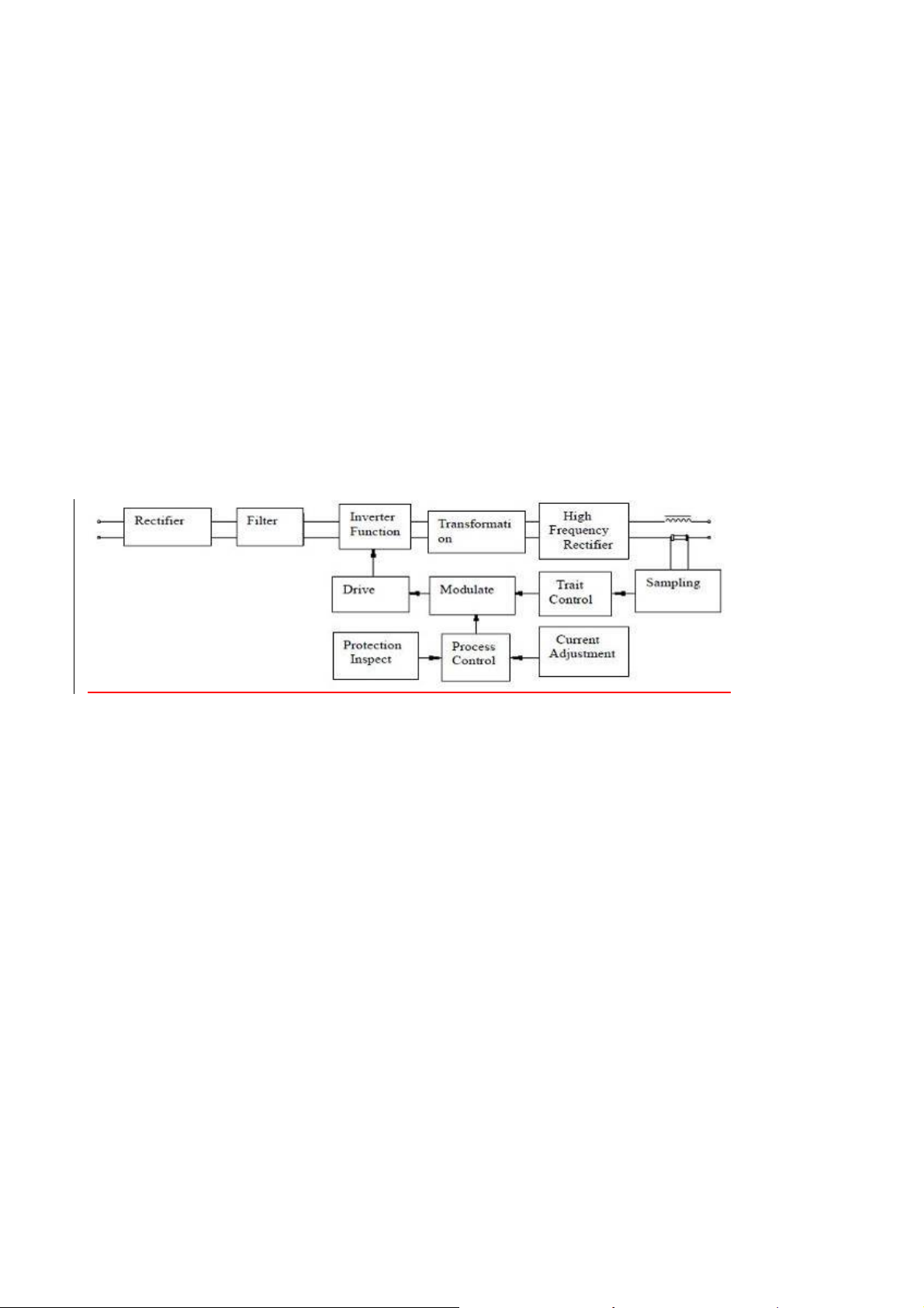
POWERTIG series inverter dc pulse argon arc welding machine adopts the advanced inverter technology, using
international advanced IGBT as a converter, supplemented by special development control circuit, make the whole
machine has high reliability, fast dynamic response, stable arc characteristics. This series welding machine has: dc
pulse argon arc welding, dc MMA arc welding, and many other functions, can satisfy the requirement of all kinds
of welding process. Its widely used in pressure vessels, construction, shipbuilding, petrochemical industries.
This manual as content has errors, or welding machine function change, will change this manual at any time,
without prior notice.
Safety Operation
Operator’s self protection:
* Comply the work safety, sanitation rules, wear relevant work protection equipments to avoid the damage to eyes
and skins.
* In welding time, cover head by the welding face shield, watch the arc only through the observing windows on
the welding veil.
* Do not let any part of your body touch the two output poles (Electrode pole and work pole) of the welders at one
time, before you are under the insulated protection.
* Do not weld in water or high humidity places.
Operator’s notices
* POWERTIG pulse inverter TIG welder is electric equipment. Its spare parts are fragile. So do not change or
adjust with a rush otherwise the switch will be damaged.
* Before every welding work, check carefully whether the welder’s correction & earth wire are correct and
reliable.
* Inflammable or explosive materials are prohibited in the welding areas.
* To ensure the air flow in the welding areas, as the welding smoke is bad for the health.
* Isolate the arc light to protect others
* Irrelevant persons are not allowed to enter into the welding area. Forbid to adjust or move the welders in the
welding time.

8
* Welders have strong electromagnetism and electric frequency disturbs. Do not let near the persons with heart
pacemaker or easily affected by electromagnetism and electric frequency.
* Do not press, pile or stress the welding wires by any apparatus. Do not bend the welding wires into very small
angle, otherwise it would hurt the inside wires to cause the hidden troubles.
* Do not touch any output joints with electric in the welding time.
* Forbid to use the welder for the pipe ice-out.
* Deliver the welder by forking machine or with base. Forbid to move by handles above the welders.
* Pay high attention on the rated duty cycle of welders to avoid the overload.
Safety protection in the welder’s installed and used places
* Protection on persons and welders under areas, where there are items dropped down.
* Dusts, Acid, Causticity airs or materials contents in the welding area air to be lower than the relevant standards
(except for these caused by the welding)
* Inflammable ,explosive or other dangerous materials are prohibited in the welding areas.
* The welders should be installed in these places, without direct sunshine, rain drench, lower humidity,
-10~+40℃.
* 50cm space to be ensured around the welders for the nice airness.
* Metal eyewinker not allowed into the welders.
* No strong shake allowed in the welding area.
* Protect the welder from the dumpage, when the welders put in the over 10° declining plane.
* Choose the installation area to avoid any disturbs to other electromagnetic equipments, when the welders used.
* Block the wind, when the air protection welding used.
Safety Check
Operator should check below procedures before every welding job:
*Make sure the welder’s earth protection is reliably connected.
* Make sure the welder’s input, output wires is fine, not exposed outside.
After the fixing of the welders, make safety check each six months by qualified persons.
* Make sure no spare parts not tightened inside the welder and clear the dusts.
* Check the spare parts on the welder panel to ensure the welder could work well.
* Check the welding wires whether aged for used
* Check the input wires whether damaged or not. If damaged, improve it.
* Check the power supply network to ensure its capacity could make the welder work normally. Ensure welder’s
input power source have security protection device.
Cut off the power supply before opening the case to check.
Please do not hesitate to contact us for technical assistance whenever you come across the problems you
can not work out or you may deem difficult to fix

9
Technical Specifications
Environment Conditions
*Ambient air temperature range:
5~+40℃in welding,water cooling
-10~+40℃in welding, air cooling
-25~+55℃in delivery, storage
* Air relevant humidity: in 40℃,≤50%; in 20℃,≤90%
* Dusts, Acid, Causticity airs or materials contents in the welding area air lower than the relevant standards
(except for these caused by the welding), No strong shake allowed in the welding area.
* Altitude degree lower than 1000m
* Protect for the rain, when the welder to be used outdoor.
* Wind speed less than 1m/s
Power supply net requirements
* Power voltage wave shape should be the actual sine wave, frequency wave less than ±1% of its rated amount.
* Power voltage wave less than ±15% of its rated amount.
Main principles of the welders
POWERTIG series inverter dc pulse argon arc welding machine adopts the international advanced IGBT and fast
recovery diode as the main power device of power transformation and transmission, can accurately control the arc,
supplemented by gas pre-flow and gas post-flow, non-contact high-frequency arc, can guarantee the arc starting
and stable welding. Combine with various protection functions make welding machine quality is reliable.
Welding machine get 220 ~ 240V AC power through wave form switch SW1, rectify by BD1 single-phase
rectifier, the capacitor C1 ~ C4 filtering into direct current (dc), via the IGBT (Q1, Q2, Q3 and Q4) composed of
bridge type inverter ac inverter into 33 KHz AC POWER, then through intermediate frequency transformer T1
transformer, after fast recovery D1-3, D4-6 rectifier, offering the stable DC power. In the output at the same time,
via high pressure of coupling transformer T2 arc with high frequency pulse coupled to the output of the negative
side, for non-contact start arc conveniently.
Main structure of the welders
POWERTIG series inverter dc pulse argon arc welding machine used to move around freely enclosure structure:
the upper part on the front panel is equipped with digital displayer, current welding mode selection button, over
voltage indicator, overheat lights, parameter adjustment of the indicator knob; The lower part is equipped with "+"
quick socket output current, output current "-" quick socket, welding gun control cable interface, as well as the
welding torch gas interface; Rear panel is equipped with cooling fan, power input lead, and the power switch, and
argon gas input interface; At the bottom of the box body is equipped with four feet and the handle.

10
Main technical specifications of the welder
No special advice on above parameter. The nameplate parameter on the welder is prior.
ITEM UNIT POWER TIG 200DPIII POWER TIG 180DPIII
ted Input Voltage V 220(220~240) 230(220~240) 220(220~240) 230(220~240)
Power Frequency Hz 50/60 50/60 50/60 50/60
Rated Input
Capacity
KVA 8.58 8.74 7.48 7.59
Rated Input Current A 39 38 34 33
Output No Load
Voltage
V62 66 62 66
Rated Working
Voltage
V18 18 17.2 17.2
Stick welding
current
A20-200 20-200 20-180 20-180
Welding Curre nt A 5~200 5~200 5~180 5~180
Base value current A 5~200 5~200 5~180 5~180
Current rise Time s 0~15 0~15 0~15 0~15
Current Drop Time s 0~25 0~25 0~25 0~25
Pulse Frequency Hz 0.5~200 0.5~200 0.5~200 0.5~200
Duty cycle % 15~85 15~85 15~85 15~85
Gas pre-flow time s 0~50
~50
~50
~5
Gas post flow Time s 0~60 0~60 0~60 0~60
Rated Duty Cycle % 20 20 20 20
Cooling Type Wind Cooling Wind Cooling Wind Cooling Wind Cooling
Effiency η≥85% ≥85% ≥85% ≥85%
Power Factor Cosφ0.73 0.73 0.73 0.73
Insulation Degree H H H H
Cover Protection
Degree
IP IP21S IP21S IP21S IP21S
Weight kg 9.3 9.3 9.3 9.3
Dimension L×W×H mm 440*175*340 440*175*340 440*175*340 440*175*340
Standards of the welders
The POWERTIG series Inverter TIG Welder according to the following standard EN60974-1 EN60974-10
High frequency arc pilot method instruction
This kind of arc pilot method is absolutely different with the traditional arc pilot method. It
does not need to connect Tungsten electrode with the work piece. It use high voltage & high
frequency pulse to make ionization on the air, transmitting the electricity by the air after
ionization, and form the arc.

11
Remark of Illustration
Welder earthing sign
TIG Welding
Drug skin electrode stick arc welding
,Single AC power supply
Single stillness frequency inverter --- transformer --- rectifier
DC current
+:+Electrode
-:-Electrode
X:Duty Cycle
I1max...A:Rated max input current
I1eff...A:Max usable input current
I2:Rated welding current
U0...V:Rated without load voltage
U1...V:Rated input voltage
U2:Rated load voltage
~50/60Hz:AC current, rated frequency 50Hz, usable frequency 60Hz
...V:Rated load voltage value
...A:Rated welding current value
...%:Duty cycle value
...A/...V~...A/...V:Output range, Rated min and max welding current and relevant rated load voltage
IP21S :Case protection degree. IP means International Protection. 2 means to prevent people use their
fingers to reach the dangerous parts; Prevent solid eyewinker, diameter less than 12.5mm, to enter
into the case; 1 means to prevent upright drip; Upright drip should have no bad influence. S means
that the water protection test was made when the moving parts (such as the rotor of the rotary
motor) was stopped.
F:Class F Insulation Degree

12
Functions
Manual metal-arc welding
This mode is equivalent to the function of the dc arc welding machine, the manual welding
electrode welding function。
Argon arc welding
Widely used in a variety of carbon steel, alloy steel, stainless steel, copper and copper alloys, nickel and nickel
alloy welding, especially suitable for thin plate welding (3 mm or less) and plate (> 3 mm) in the opening of one
side welding groove butt weld, double-sided molding, backing welding process, especially suitable for argon arc
welding backing, dc manual arc welding more than cover the welding process.
DC pulse argon arc welding
Panel Settings "hand arc/argon arc" the argon arc position, "steps 2/4" set "step 2" position. Panel Settings
"hand arc/argon arc" the argon arc position, "steps 2/4" set "step 2" position.
Is suitable for thin plate welding, and is suitable for any position of continuous welding, do not need to adjust the
welding specification for welding position change. In addition to get the big melt in both deep, and expect to
reduce the welding heat affected zone, pulse welding current, base value current, pulse width of the reasonable
choice will be good to meet specific needs。Pulse welding current is to strengthen the mixing of molten pool, to
minimize the pores. Under the same line energy, dc pulse arc than dc constant current arc penetration is big, pulse
current of coagulation, form and normal form is different, it can improve the mechanical properties of a particular
joint. Properly adjusting the parameters of the pulse and the welding speed, smooth dc pulse argon arc welding
can form uniform and controllable fusion zone (scales).
Pulse frequency(POWERTIG (KD)series)
Pulse:Is in a state of current (dc), to the current surge in the form of a pattern. The current supply in pulse way,
set up the welding current and base current, set the pulse frequency and pulse width parameter.
“2step/4step” option
Under argon arc welding method, the "steps" 2/4 "" set in step [4], press the torch switch, arc is established
and began to burn, the arc work in" striking current ", At this time you can put away the torch switch, electric arc
by the striking current phase shifted to the current slow rise stage, after the current slow appreciation set current
into the welding current stage; Again press the gun switch, electric arc by the welding current into the "current
slow down" phase, when the current drop to crater arc current stage in "crater arc current, the loosen rob switch,
arc extinguishing, welding process is over. Without this feature when 2 step.

13
Current Adjustment Instruction
Welding current
Arc welding current refers to the "hand/argon arc" function mode Settings of the welding current size, at the
same time refers to the pulse argon arc welding of pulse peak electric current. At this time of the arc heat is big,
the workpiece heated, it is used to welding.
Base Current
Base current means the minimum current in the pulse current welding. In the base current time, the arc has
the smallest quantity of heat, so the work piece has the ability to transfer away the quantity of heat in the melted
bath, got in the peak time.
Pulse frequency
Pulse frequency refers to the pulse argon arc welding state, the current adjust speed rate between welding
current and base value current.
Duty ratio
Duty ratio is welding peak current’s ratio during one cycle time under pulse argon arc welding condition.
Duty ratio in the range of 15-85% is adjustable. Such as: the frequency of 5 hz (its pulse cycle is 200 ms) of pulse
current in each cycle of welding current peak time is 80 ms, so, the duty ratio of pulse are as follows:
80÷200×100% = 40%.
The current slow rise time
Current slow rise time refers to the time of from starting arc current to normal current for welding. It uses to
slow down the current rising rate, current slow rise, gradually melted the artifacts, ensure that when the welding
current will suddenly increase.
The current slow down time
Current ramp down time refers to the time of from the welding current dropped to reap arc current. It slows
the rate of decline in current and electric current to slow down, gradually submerged arc pit, ensure the quality of
weldingattheendofthewelding.
Gas pre-flow
It refers to setting a suitable gas delivery time before the arc ignition in advance. It can ensure the starting
point of the molten pool is not oxidation.
Gas stopping delay time
Gas stopping delay time means the protection gas feeding time value after the arc winked to protect the
work piece away from the oxidation. It’s very necessary to continue feeding the protection gas into the melted
bath after the welding finished, as the melted bath still needs some cooling time, as though the winked arc could
not heat the work piece any more. This welder set inside to be about 5s (changeable according to customer’s
requirements).
Welder Installation
Welder Placement
* Welder should be placed in the dry, dustless place, without chemical caustic, flammable,

14
explosive gas or goods around.
* Avoiding direct sunshine or rainfall, ambient temperature in the range of -10~40 ℃(water
cooling model, 5~40℃)
* Apparatus to exclude wind and smoke should be equipped if the inside aeration is not sound.
Connected with power source (see the input wiring drawing)
Connect the 【Power input wire】in the behind plate of the welder into the 220~240V power
source (electricity network), with circuit breakers and earthing wires; Forbid to input 380V power
source into the welder (380V power source will damage the welder badly); Forbid to input the
earthing wire into the electricity network, otherwise you would bear the results yourself. Notice:
Connect the electricity network with earth, instead of Zero.

15
Input wiring drawing
* Power supply configuration of one welder:
Item POWERTIG200KD PULSE ii
ACB(A)≥40
FUSE(A)40
KNIFE SWITCH(A)≥60
POWER LINE(mm2)≥4
Note: the breaking current of fuse is twice of its rated working current.
Connected with Argon (see the input wiring drawing)
Install the decompression valve (Argon meter) onto the Argon bottle, connect the gas hole on the Argon
bottle with the Argon input hole on the behind panel of the welder with the gas pipe, supplied together with the
welder, tighten the holes with also supplied loop.
Connected with work piece (see the input wiring drawing)
Insert the quick plug of the cable into the【Power output “+” Electrode quick Socket】in the front panel of the
welder and tighten clockwise; The earthing clamp in the another end of the cable connected with the work piece.
Output wiring drawing
Out put connecting under MMA model
Connecting the cable the “-“ in font panel and tighten up, the other end connecting to the work
piece
“- ”connecting work piece “+ ”connecting electrode holder
Gas connector in Torch
Negative quick connector
Positive quick connector
Control cable in Torch

16
Operation
ATTENTION:The protection grade of POWERTIG DC pulse Welder is IP21S. It is forbidden to
put in a finger or insert a round bar less than 12.5mm (metal bar in particular) into the welder. No heavy force can
be employed on the welder.
Front panel real panel
1.welding mode
selection switch
2.Dc/pulse select switch 3.Steps 2/4 option switch 4.digital meter
5.Power indicator 6.Overvoltage and
under-voltage indicator
7.Over heat indicator 8. Parameter setting
knob
9. Socket “+” 10.Connector for Torch
Control
11.Socket “-” 12 . Gas connector
for torch
13.Gas connector 14. Power switch 15.Power core
Attention:
* The ‘Protection Indicator’ on the panel will be on after a long time operation, it shows that the inner temperature
is over the permitted data. The machine should be stopped using for some time to let it cool down. It can
continually use after the light is off.
* The power source, Argon valve and cooling water should be switch off after the operation or leaving job site
temporarily.
* Welders should dress canvas work suit and wear mask to prevent arc light and thermal radiation;

17
* Light separating screen should be put in the job site to prevent arc hurting other people;
* Inflammable or explosive materials are prohibited to access the job site;
* Every connector of welder should be connected correctly and grounded reliably
* Manual Arc Welding
When put ‘welding mode selection switch’ on ‘arc welding’ and Dc/pulse select switch on DC position, it can be
used as manual arc welding.
Choose Parameter setting knob enter into welding current parameter setting to adjust welding current and also
can enter into pushing force current parameter setting to adjust pushing force current.
DC TIG Welding
When put welding mode selection switch on Tig welding and put DC/ pulse select switch on DC position, Put
Steps 2/4 option switch on step 2, it can be used as DC TIG Welding.
Choose Parameter setting knob enter into welding current parameter setting to adjust welding current and also
can enter into current increasing time parameter setting to adjust increasing time, enter into current decreasing
time parameter setting to adjust decreasing time.
Choose Parameter setting knob enter into Postflow Time parameter setting to adjust Postflow Time.
Choose Parameter setting knob enter into Preflow Time parameter setting to adjust Preflow Time
DC Pulse TIG Welding
When put welding mode selection switch on Tig welding and put DC/ pulse select switch on DC position, Put
Steps 2/4 option switch on step 2, it can be used as Pulse TIG Welding
Choose Parameter setting knob enter into pulse welding current parameter setting to adjust Pulse welding
current.
Choose Parameter setting knob enter into Pulse background current parameter setting to adjust Pulse
background current.
Choose Parameter setting knob enter into pulse frequency parameter setting to adjust pulse frequency.
Choose Parameter setting knob enter into duty cycle parameter setting to adjust duty cycle.
Choose Parameter setting knob enter into current increasing time parameter setting to adjust increasing time
Choose Parameter setting knob enter into current decreasing time parameter setting to adjust decreasing time
Choose Parameter setting knob enter into Post flow Time parameter setting to adjust Post flow Time.

18
Welding regulations parameter table (only for reference)
Mode
Material
Type
Designe
d Joint
WORK
Thickne
ss
(mm)
Wire
Dia
Φ
(mm)
Welding
Current
(A)
Polarity
Argon Flow
(dm3/min)
Tungste
nStick
Dia Φ
(mm)
Angle
Top Dia
Φ
(mm)
DC
Stainless Steel
Vertical
Joint 1.6~3.0
1.6~2.5
50~90
DC Positive
8~12
1.0 12~20° 0.12~0.25
V groove
>
3.0~6.0 70~120 1.6 25~30° 0.50~0.75
X groove >6.0~12 2.5~3.2 100~150 10~14 2.4 35~45° 0.75~1.10
Arc
weelding
Carbon steel
Joint
≤4 3.2 160~210 / / / /
4~12 3~4 210~270 / / / /
>12 ≥4 260~300 / / / /
Common faults and solving methods
No. Breakdown Analysis Solutions
1Cooling fan
Not work
Cooling fan broken Replace the fan
Cable broken/fallen off Find the disconnected wire and
Connect reliably
2No piloting
high frequency
Torch switch broken Replace the torch
Main PC board broken Replace the PC board
Cable broken/fallen off Find the disconnected wire and
Connect reliably
3No Argon
output
No Argon input Check the flow meter and resume
supplying gas to the welder
Main PC board broken Replace the PC board
Electromagnetism Valve
broken Change the electromagnetism valve
Gas path blocked Clear the eyewinker and dredge the gas
path
4Protection
Indicator On
Overheat inside the
machine
Become normal after the inside
temperature reduced
Thermal relay broken Replace the thermal relay
Over/Lack voltage more
Than 15% Become normal after voltage ok

19
5Panel knob not
adjustable
Relevant potentiometer
broken
Replace the potentiometer
Main PC board broken Replace the PC board
Cable broken/fallen off Find the disconnected wire and
Connect reliably
6No display on
the AMP meter
Digital Amp meter
broken
Change the meter
Cable broken/fallen off Find the disconnected wire and
Connect reliably
Main PC board broken Replace the PC board
7Arc piloting not
smooth
Wrong connection
between torch and
welder
Check and correct according the manual
Argon not pure Use 99.99% pure Argon
Tungsten electrode or
pin broken
Use qualified Tungsten electrode
8Powertrip
First turning on after
power long time (2days
more) off
Not fault, trip caused by the charging
filter capacitor in the main board,
return on the power switch
9Others Please contact with the supplier/manufactuer

20
Explosive view and spare Parts List
Note: above table spare parts list is just for reference.
No. Code English name QTY
120020170017 handle 1
211010011797 top cover 1
311020013625 mounting plate 1
420070800288 rocker switch 1
520030060074 YZ power cable 1
620040300007 cable protection cover 1
711010032555 back panel up fixed plate 1
820050050694 fan window 1
920050050691 back panel 1
10 20050170013 cable press plate 1
11 20020020035 gas connector 1
Table of contents
Other Mweld Welding System manuals