MX MX R05N User manual

FRONT LINKAGE
MXR05N
MXR08N
User Manual
Please read carefully before using
MX front linkage
EN 368483 AD -0919
Translation of the original manual


Dear user,
We thank you for placing your trust in our product and hope you will nd your MX front linkage satisfactory in
every way.
By taking a few minutes to read this manual, you will be able to obtain the best results from your MX front linkage,
extend its lifespan and work in complete safety.
The front linkage user manual before you is an important document, please retain it in order to be able to refer to
it if required. Make it available to any other users and hand it over it to any new owner in the event of your MX front
linkage being sold on.
The illustrations and technical data shown in this document might not exactly match your front linkage; operating
requirements will nevertheless remain the same.

TABLE OF CONTENTS
1. SAFETY INSTRUCTIONS 4
2. OPERATING REQUIREMENTS 5
3. SAFETY STICKERS 6
4. IDENTIFICATION PLATE 6
5. DESCRIPTION 7
6. SETTING FRONT LINKAGE TO OPERATING POSITION 8
7. HITCHING A FRONT IMPLEMENT 10
8. UNHITCHING A FRONT IMPLEMENT 11
9. SETTING FRONT LINKAGE TO TRANSPORT POSITION 12
10. FRONT POWER TAKE-OFF WITH TRANSMISSION SHAFT* 14
11. HITCHING TRIANGLE* 15
12. AUXILIARY HYDRAULIC LINE* 15
13. CONTROL 16
14. MAINTENANCE 17
15. TECHNICAL SPECIFICATIONS 18
* Depending on conguration

3Subject to modications
• 19, rue de Rennes • BP 83221 • F - 35690 ACIGNÉ
The operator must read this manual before using
themachineforthersttime.
Familiarise yourself with:
— Safety rules and operating requirements.
— Hitching and unhitching an implement.
— Full use of the controls.

4Subject to modications
• 19, rue de Rennes • BP 83221 • F - 35690 ACIGNÉ
1. SAFETY INSTRUCTIONS
— The tractor – linkage combination must only be operated by trained and experienced personnel.
— When the tractor is tted with a front linkage and front-end loader, the user is required to unhitch the loader before using the MX front linkage (please refer
to the loader user manual for the unhitching procedure).
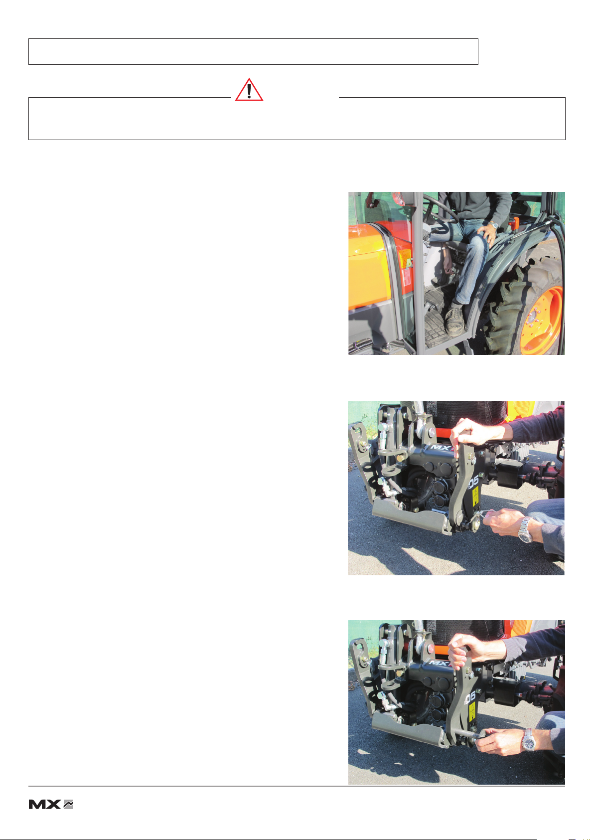
— CAUTION: before using of the front loader, please check the front linkage is locked (with the hydraulic tap), and the arms are folded or removed (see
chapter "folded arms position").
— Only operate the front linkage from the operators seat or by using the MX factory-supplied external controls. Keep controlling until movements stop.
— The controls for operating the front linkage must be of the "spring return" type with the exception of the oating position which may be held by a detent system.
— Do not leave the control station without stopping all control movements.
— You must ensure that nobody is in the area while the front linkage and tractor are in use.
— The transport or elevation of persons using the front linkage is forbidden.
— Before moving with a front implement tted, check and ensure that the tractor-front implement assembly is stable by tting a counter weight at the rear of
the tractor. This should ensure that 20% of the gross weight (tractor-front implement) remains on the rear axle of the tractor for optimum safety while
travelling and working.
— The maximum front axle loading specied by the tractor manufacturer must not be exceeded.
— The front tyres maximum safe load provided by the tyres’ manufacturer must not be exceeded.
— Check tyre pressures regularly.
— An implement hitched to the front linkage must be capable of being lifted through the full travel of the linkage. Any excess load impeding this travel is strictly
forbidden.
— Before any operation, the user must ensure that the front linkage is in proper working order and can be used in complete safety.
— When travelling on the road with a front implement, the front linkage must always be in a raised position and it is imperative that the regulations governing
use on the public highway be observed (size, implement markings, etc.).
— When driving on the road without a front implement, the front linkage must be set to the transport position (see "Setting the front linkage to transport
position" section).
— Whenever the tractor is stopped momentarily or for an extended period, the engine must be shut down and the linkage lowered.
— The tractor must never be towed from an anchoring point on the front linkage.
— Check periodically to ensure that safety pins and bolts are in place. Do not replace them with any other items, such as nails, wire, etc.
— Any work involving fault tracing (diagnostics) and/or disassembly of parts may only be undertaken by a skilled technician who will start with an assurance that
the work will be carried out in complete safety for himself and his surroundings.
Caution!
— The MX front linkage hydraulic system is designed to withstand a maximum operating pressure of 200 bar.
— Never make any changes to the hose connections.
— Any instance of MX front linkage being tted which ignores the recommendations in the MX price list in force on the date of purchase will void MX warranty
on the entire MX supply.
— Any modication to any part of the MX supply (rams, arms, linkage frame, etc.) or usage of a component installed on the MX front linkage which has not
originated from MX will void MX the warranty and liability on the entire MX supply.
— Use only genuine MX spare parts. Do not modify your MX front linkage yourself or have it modied by anyone else, without applying for written authorisation
from MX in advance. Failure to comply these rules may make your MX front linkage hazardous. In the event of damage or injury, MX shall not be held
responsible in any way.
— Warranty cover will cease immediately in the event of failure to observe the standards and instructions for use and maintenance of the MX front linkage
as stipulated in the user manual.

5Subject to modications
• 19, rue de Rennes • BP 83221 • F - 35690 ACIGNÉ
2. OPERATING REQUIREMENTS
2.1 Implement hitching.
The front linkages are designed to receive implements which comply with the hitch dimensions specied in ISO 8759-1
standards for category II.
The distance of the implement’s hitch points must
be 436 (dimension A, cat. 1N standard) with a linkage pin
of 22 mm diameter (Ø D).
The vertical height of the implement must be 360
(dimension H).
2.2 Front overhang and use on the ground.
The implement must be hitched as close as possible to the attachment points on the front linkage. In fact, the longitudinal
overhang generates considerable stresses on the front linkage (due to leverage). The more compact the implement xing,
the less strain there will be on the equipment. Using a compact implement also improves lifting performance.
This category of linkage is not designed for working the ground. You are strongly recommended not to t soil engaging
implements, so as to safeguard the structure of the machine.
Caution!
Requirements for implement hitching and for working on the ground must be strictly complied with. Any deviation from
the requirements risks causing serious damage for which MX cannot be held liable.
Hitching an implement with a dimension H less than that specied above will overload the upper link bar, causing
damage to it.
Hitching an implement with dimension H in excess of that specied above can cause damage to the front of
the tractor (bonnet, grille, etc.) on lifting.

6Subject to modications
• 19, rue de Rennes • BP 83221 • F - 35690 ACIGNÉ
3. SAFETY STICKERS
A safety sticker is afxed to the front linkage. Keep it readable and clean; replace it if damaged.
4. IDENTIFICATION PLATE
The identication plate is located on the right-hand side of the front linkage frame.
The serial number and front linkage model shown on this plate must be quoted in any request for spare parts information
or technical assistance.

1
3
4
5
6
7
8
12
11
2
10
9
7Subject to modications
• 19, rue de Rennes • BP 83221 • F - 35690 ACIGNÉ
5. DESCRIPTION
1: Right-hand arm
2: Left-hand arm
3: Pin
4: Pin
5: Ram
6: Linkage frame
7: Towing clevis (use a 30 mm diameter pin)
8: Frame
9: 3rd link bar
10: Safety clip
11: Roll cage clip
12: Arm locking

8Subject to modications
• 19, rue de Rennes • BP 83221 • F - 35690 ACIGNÉ
6. SETTING FRONT LINKAGE TO OPERATING POSITION
6.1 Choose a level and solid surface.
The tractor engine is to be turned off and the hand brake applied.
6.2 Leave the cab and remove the locking pin from the left-hand arm.
6.3 Hold the left-hand arm and withdraw the pin.
Caution
This operation must be carried out by the driver who must leave his seat and
ensureallcontrolsarelockedoutwhileheisworkingonthefrontlinkage.

Fermé Ouvert
9Subject to modications
• 19, rue de Rennes • BP 83221 • F - 35690 ACIGNÉ
6.4 Swing the arms forwards up to the desired position.
6.5 Ret the pin and secure it with the locking pin.
6.6 Repeat operations 6.2 to 6.5 for the right-hand arm.
6.7 Open the stop valve.
Closed Open

10 Subject to modications
• 19, rue de Rennes • BP 83221 • F - 35690 ACIGNÉ
7. HITCHING A FRONT IMPLEMENT
The linkage is in the operating position.
7.1 Open the locking catches on the hitching hooks and hitch up
the implement.
7.2 Close the locking catches on the hitching hooks.
Two possible scenarios: position 1, xed position
position 2, oating position
arm in oating position; the implement follows the contours of
the ground
7.3 Hitch the 3rd link bar to the bracket on the front implement.
Caution
This operation must be carried out by the driver who must leave his seat and
ensureallcontrolsarelockedoutwhileheisworkingonthefrontlinkage.
1
2
2

11 Subject to modications
• 19, rue de Rennes • BP 83221 • F - 35690 ACIGNÉ
7.4 Set the length of the 3rd link bar to obtain the desired geometry
for the front implement.
Lock the adjustment of the bar by means of the lever locknut.
8. UNHITCHING A FRONT IMPLEMENT
8.1 Place the front implement on level and solid ground. Apply
the tractor handbrake.
8.2 Release the 3rd link bar from the front implement bracket.
Checks to be carried out before starting work
— Carry out a lift test checking that the tractor and front implement interact correctly. Pay particular attention to checking
the gap between the upper link bar and the bonnet of the tractor.
— Check that all pins and locking pins are tted and secured correctly.
— Check the locking status of the hitching hooks (the catches must be retracted correctly).
Caution
This operation must be carried out by the driver who must leave his seat and
ensureallcontrolsarelockedoutwhileheisworkingonthefrontlinkage.

12 Subject to modications
• 19, rue de Rennes • BP 83221 • F - 35690 ACIGNÉ
8.3 Reposition the 3rd link bar on to the front linkage frame.
8.4 Unlock the hitching hooks and lower the linkage arms to release
the implement.
9. SETTING FRONT LINKAGE TO TRANSPORT POSITION
9.1 Choose a level and solid surface. Raise the front linkage arms.
Stop the engine and put on the hand brake.
Caution
This operation must be carried out by the driver who must leave his seat and
ensureallcontrolsarelockedoutwhileheisworkingonthefrontlinkage.

Fermé Ouvert
13 Subject to modications
• 19, rue de Rennes • BP 83221 • F - 35690 ACIGNÉ
9.2 Shut the isolator valve.
9.3 Remove the locking pin while holding the left-hand arm.
9.4 Swing the left-hand arm rearwards and ret the pin and
locking pin.
9.5 Repeat operations 9.3 to 9.4 for the right-hand arm.
Closed Open

β
α
Leergewicht
14 Subject to modications
• 19, rue de Rennes • BP 83221 • F - 35690 ACIGNÉ
10. FRONTPOWERTAKE-OFFWITHTRANSMISSIONSHAFT*
SAFETY RULES AND RECOMMENDATIONS IN RESPECT OF POWER TAKE-OFF
— Never start the engine with the power take-off engaged.
— Beforehitchingtheimplement,checkthatthedirectionofrotationfortheimplement
is compatible with the front power take-off.
— Check whether the speed and power of the implement are matched to the power
take-off. Otherwise, the implement must not be hitched and connected.
— Check the length of the PTO shaft between the implement and the front power
take-off and adapt it accordingly.
— The PTO shaft universal must be tted with a suitable guard (complying with
the ISO 5673-1 standard).
— Never lift or lower the front linkage with the power take-off under load.
— Check angles a and b of the implement and power take-off universal joints.Adjust
the upper link bar to make these angles approximately equal in terms of working
position. The maximum values for angles a and b will vary according to the type
of universal joint used (please refer to the universal joint manufacturer’s user
manual).
— Any maintenance on the implement must be carried out with the engine shut
down, the implement completely at rest and hydraulically locked.
— Each time the power take-off is used, grease the sliding section of the shaft and
the universal joint spiders beforehand.
— Never make any changes to the electrical connections.
— Observe the maintenance instructions (please refer to the "Maintenance" section).
— The safety instructions in this manual are not to be construed as a replacement
for safety regulations, insurance requirements or national and local legislation.
Ensure your machine is tted with the correct equipment as required by law and
local regulations.
10.1 Hitch up the implement (please refer to the section "Hitching a front
implement").
10.2 Connect the PTO shaft to the front power take-off.
The tractor engine must be stopped.
10.3 Restart thetractorand startthe front powertake-off(refer tothe tractor’s
user instructions).
* Depending on conguration
Checks to be carried out before starting work
— Check that the tractor, implement and transmission shaft interact correctly throughout the full lifting stroke before
engaging the power take-off.
Caution
This operation must be carried out by the driver who must leave his seat and
ensureallcontrolsarelockedoutwhileheisworkingonthefrontlinkage.

15 Subject to modications
• 19, rue de Rennes • BP 83221 • F - 35690 ACIGNÉ
11.HITCHING TRIANGLE*
Attachment of the female A triangle on implements – each implement will
have its own female triangle.
Attachment of the male B triangle on the linkage (see "Hitching a front
implement" section").
Remove the pin reference 3 from the triangle reference 1.
Fit the male triangle reference B in the female triangle reference A.
Retighten the pin reference 3 in the triangles. This acts as a lock.
Readjust the upper link bar if necessary.
12. AUXILIARYHYDRAULICLINE*
This supplies a hydraulic unit in front of the linkage.
12.1 Connect the hydraulic hoses of the implement to the 3/8" female
couplings. Release the pressure from the hydraulic system to
make the connection of the hoses easier.
12.2 Operate the hydraulic line using the tractor or the MX control
valve. (Refer to the "Control" section).
* Depending on conguration

16 Subject to modications
• 19, rue de Rennes • BP 83221 • F - 35690 ACIGNÉ
13. CONTROL
Using the factory-tted control valve on the tractor. Refer to the user
manual for the tractor.
13.1 Using the MX loader control valve.
13.1.1Raising and lowering the MX front linkage. Move the MX
monolever handle forwards or backwards.
13.1.2Operating the auxiliary hydraulic line (depending on
conguration). Move the MX monolever handle to the left or to
the right.
In order to operate a second auxiliary hydraulic line, press and
hold the green button on the monolever handle and move it to
the left or to the right.
* Depending on conguration

17 Subject to modications
• 19, rue de Rennes • BP 83221 • F - 35690 ACIGNÉ
14. MAINTENANCE
Lubricate every 10 hours and after each wash (water drives grease out)
and particularly after washing with a pressure washer. See lubrication
points opposite.
Check fasteners for tightness after 10 and 50 hours of operation, every
100 hours thereafter, keeping to the recommended tightening torque.
On each occasion, check before and after use for any hydraulic leaks
which might have appeared and that the pins and locking pins are
all tted.
The frame and rams are tted with wear bushes. If there is excessive
play (approx. 2 mm), replace them with new genuine MX bushes.
Front power take-off:
After the rst 50 hours and every 500 tractor operating hours thereafter (or once a year):
— Drain the oil and replace the lter with a new genuine MX one (see lter removal procedure below).
— Next, rell the housing with oil up to the level shown opposite. Recommend oil type STOU (Supper Tractor Oil Universal)
10W30 or 10W40 or equivalent.
NOTE: Check power take-off housing oil level regularly and top up as necessary.

18 Subject to modications
• 19, rue de Rennes • BP 83221 • F - 35690 ACIGNÉ
15. TECHNICALCHARACTERISTICS
R05N R08N
Front linkage category 1N 1N
Lifting capacity at the end of the linkage arms* 500 kg 800 kg
Lifting capacity with the centre of gravity of the implement positioned 610 mm
forward of the ball ends* 300 kg 550 kg
Theoretical arm spacing 365 mm 365 mm
Height of linkage arms off the ground*
In lowered position (1) < 200 mm < 200 mm
In raised position (2) > 450 mm > 450 mm
Hitching hooks - -
Upper link length Cat.1/345to500mm Cat.1/345to500mm
Power take-off (PTO) with transmission shaft**
PTO output speed 2000 rpm 2000 rpm
Output shaft prole (DIN 9611) 1"3/8-6splines 1"3/8-6splines
Direction of rotation (viewed from tractor seat) clockwise clockwise
Front power take-off (PTO)**
Max. PTO power 100 hp 100 hp
PTO output speed 1000 rpm 1000 rpm
Output shaft prole (DIN 9611) 1"3/8-6splines 1"3/8-6splines
Direction of rotation (viewed from tractor seat) clockwise clockwise
* Average gures They may vary in line with tractor specications.
** Option available dependent upon tractor - front linkage compatibility.
This manual suits for next models
1
Table of contents
Other MX Tractor Accessories manuals
Popular Tractor Accessories manuals by other brands

enorossi
enorossi G2V 310 3P/PT Use and maintenance manual

Avantco
Avantco S30 Operator's manual for Attachment

Ventrac
Ventrac KD482 Operator's manual & parts drawings

Harvest TEC
Harvest TEC 880 owner's manual

Kellfri
Kellfri 32-S500 operating instructions

Extreme Max
Extreme Max 5500.5094 Assembly & operating instructions

Tiger
Tiger BENGAL JD6110-30M/R T4F Mounting and operating instructions

Degelman
Degelman PRO-TILL 41 quick start guide

diamond mowers
diamond mowers ALL AMERICAN DISC Operator's manual

Spearhead
Spearhead RC 132 Handbook & Parts Book

Tiger
Tiger JD6175R Mounting and operating instructions

Alamo
Alamo Schulte SRW 1400 OPERATOR’S MANUAL WITH PARTS LISTING