MY
FireplaceBlower
NOTE: Diagrams and Illustrations NOT to Scale
Page 4 of 5
Installations in Canada must conform to the current CAN/CGAB-419.1 and .2 Gas Installation Code and local regula-
tions. When installing the blower fan kit, it must be electrically grounded in accordance with CSA C22.1 Canadian
Electrical Code Part 1 and/or Local Codes.
Installations in the USA must conform to local codes, or in absence of local codes or the National Fuel Gas Code,
ANSI Z223.1-1988. When installing the blower fan kit, it must be grounded in accordance with local codes, or in
absence of local codes, with the National Electrical Code, ANSI/NFPA 70-1987.
My Fireplace Blower LLC produces and sells aftermarket replace blower kits; which require consultation
of an Owner’s Installation Manual from the Manufacturer of a particular replace model number for in-
stallation. During Installation of a replace blower kit or replacement blower, refer to the Owner’s Instal-
lation Manual for your particular replace model to obtain supplemental information. My Fireplace Blower
LLC is not responsible for any damage incurred during installation or resulting from installation of a re-
place blower kit, which was directed and/or conducted from the information within this document.
Installation Videos:
Installation Instructions:
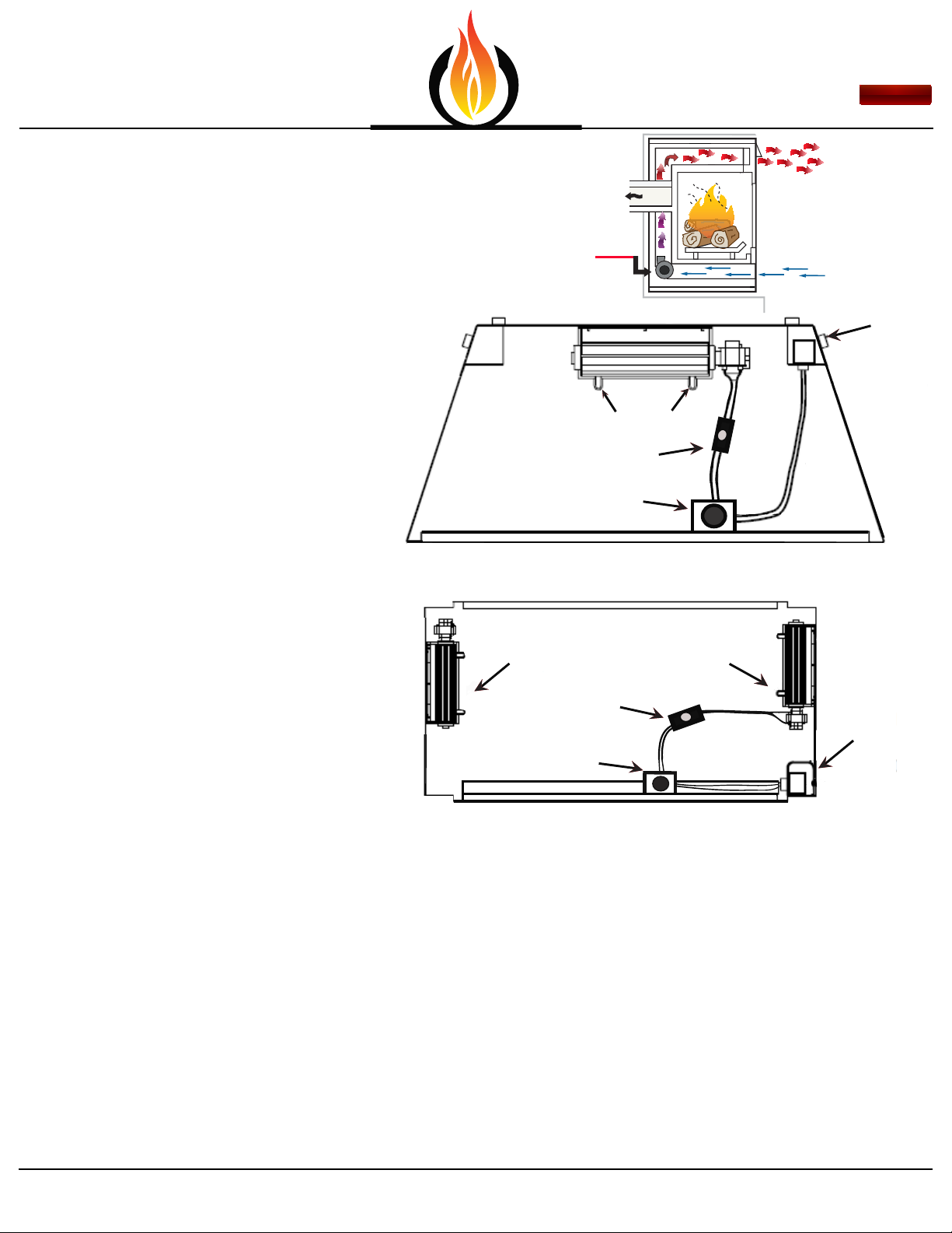
Step 6:
Insert 3-Prong Plug into top power receptacle of
the Junction Box (Figure: 8).
•Wiring Diagram for this Blower Kit is illustrated in
Figure: 7. Blower operates on 120V/60Hz power.
Figure: 8
CLICK
CLICK
CLICK
Finishing Steps:
If appliance is connected to a gas supply, turn it
back on.
If Appliance is connected to 120 Volt Power, turn it
back on.
Installer is responsible to check local codes
and read all instructions prior to installation.
Layout designed in U.S.A. © 2015
My Fireplace Blower
Burlington, Wisconsin
1-800-466-4045
MyFireplaceBlower.com:
Wall Mounted Variable Speed Control Option:
The Following instructions are only needed if you
have a wall switch which is dedicated to turn the
Junction Box(120v Power Supply) in the vent space
under the rebox ON/OFF.
AND, you wish to replace this switch with the
Variable Speed Control.
•You will need a wire stripping tool, crimping tool,
11/16 socket or wrench, and phillips screw driver.
**Make sure Power/Circuit Breaker to the existing
switch and Gas are still off if choosing this option.**
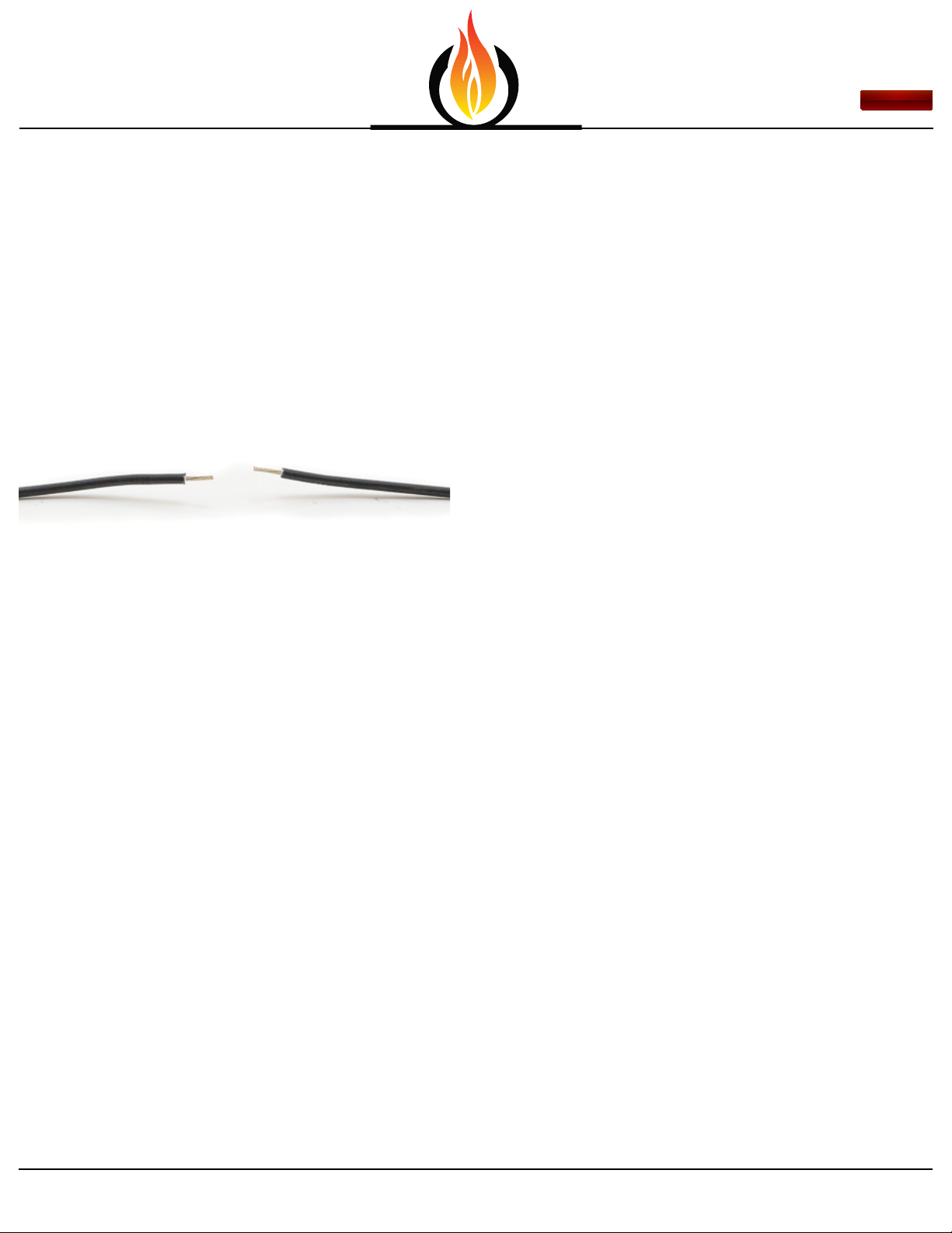
Step A: Cut the Black wires next to the yellow
bands. (Figure:9).
Plug into Top
Figure: 9
Cut Here