Installation Guide V2.1 5
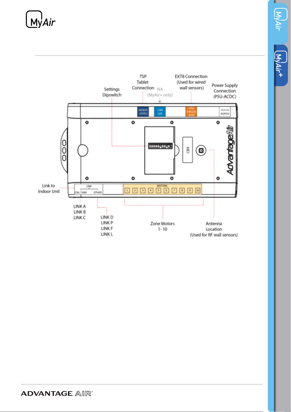
4 - CB9 SETUP
The standard CB9 Control Box will control units from the following suppliers:
• Carrier, Midea, Rinnai, York
• Samsung (14kW or less)
• Haier
Samsung units - LINK A
1. Ensure power to the air conditioner is OFF.
2. Connect Samsung Remote (MWR-WE10), then turn power ON.
3. Congure static pressure using manufacturers instructions. Run unit in cooling /
heating to test, then power OFF.
4. Disconnect the Samsung remote from the indoor unit and replace with LINK A
cable. Connect the other end of the LINK A cable to the CB.
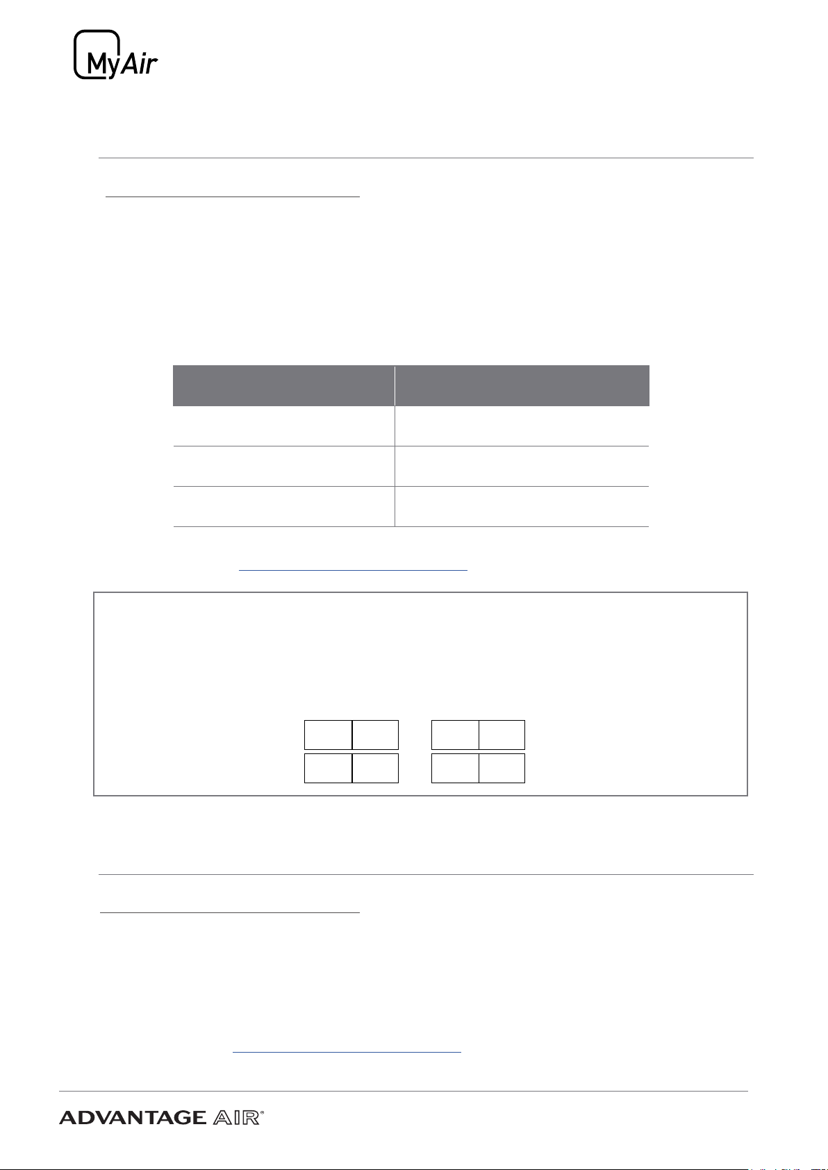
CABLE CORE COLOUR INDOOR UNIT TERMINAL
RED F3
BLACK F4
5. Go to Section 18 SYSTEM CONFIGURATION to complete install.
Haier units - LINK B
1. Ensure power to the air conditioner is OFF.
2. Connect Haier remote, then turn power ON.
3. Run the unit in cooling / heating to test, then power OFF.
4. Follow Haier instructions and connect a YCJ-A002 Modbus adapter board
(supplied by Haier) to the indoor unit. Then connect the LINK B cable to the CB and
then wire the other end to the modbus board terminals.
CABLE CORE COLOUR MODBUS BOARD TERMINAL
RED CN1-A
BLACK CN1-B
WHITE GND
5. The Haier wall remote must be connected and installed in order to:
A. Measure room temperature; and
B. Enable return air mode.
6. Go to Section 18 SYSTEM CONFIGURATION to complete install