SyxthSense Ltd
Copyright © 2013 SyxthSense Ltd. All rights reserved - 02/2013
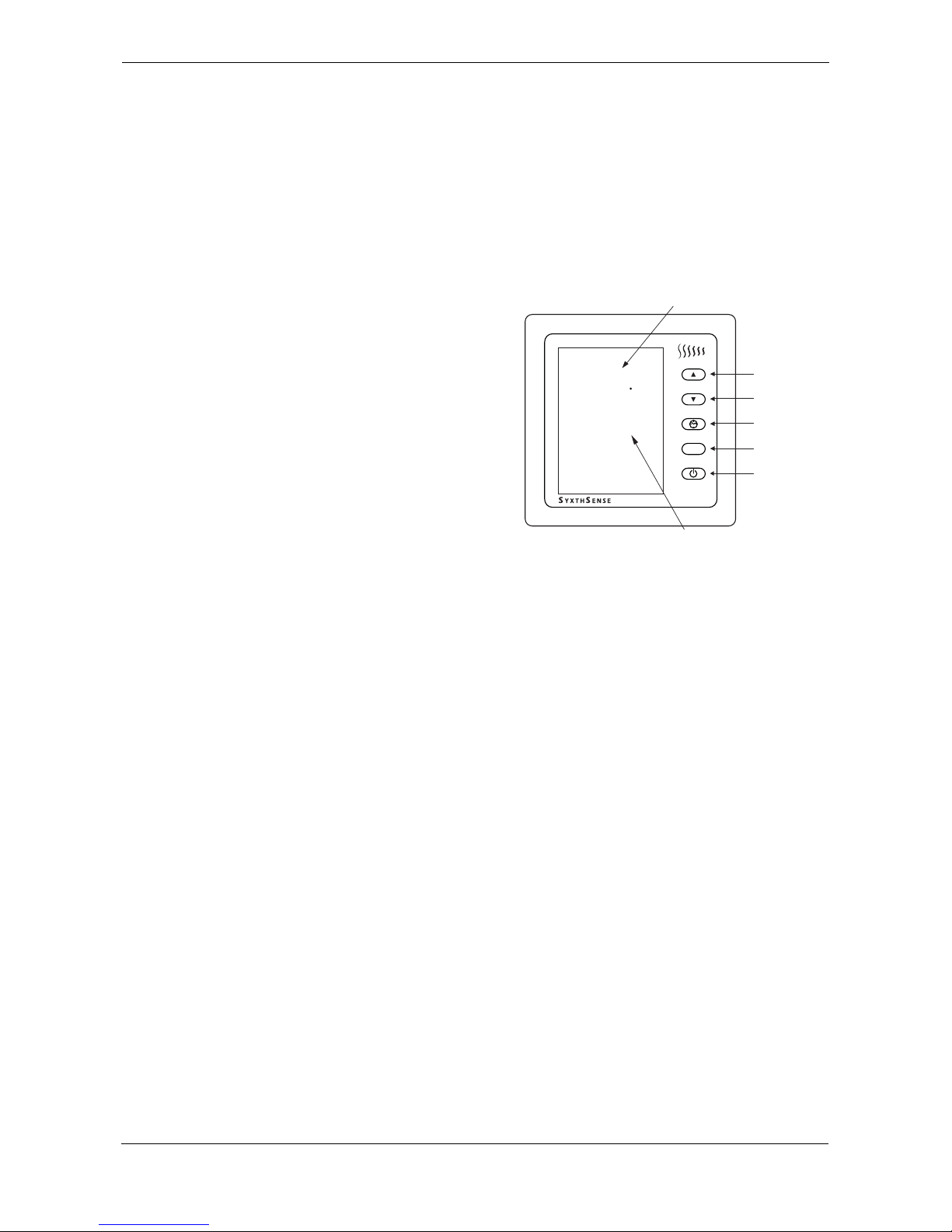
PS TH6.90 - 4/5
Online store: www.syxthsense.com
Enquiries: T: 0844 840 3100 F: 0844 840 3200
External On/Off Override
(e.g. telephone interface)
If an external sensor is not in use
an advanced setting can be
activated to override the SST
thermostat remotely on/off. This
can be used, for example, with a
telephone or mobile text message
interface for remote heating
switching.
GND
B
A
N
RS
N
FS
LOAD
L
SST THERMOSTAT
Remote Override
Switch e.g telephone
interface or GSM interface
Contact Open = Thermostat OFF
Contact Closed = Thermostat ON
(SyxthSense part nos
ITPF-221 and ITPR-321).
To activate this function configure
the Advanced Parameter No. 3 to a
setting 2.
If the unit is remotely overridden
OFF, the unit can be locally
overridden ON by pressing OFF
button. Note: The thermostat
needs to detect close to open
transition to switch again off
remotely.
5 Temperature Sensor Reading Adjust When viewing parameter 5 on the SST, the current
room temperature is shown. The user may then
adjust this reading by using UP/DOWN keys to
match the user preference (0.5°C steps). The
maximu effect on the sensor is +/-10°C.
Example: SST Reading = 21°C, Handheld
Thermometer Reading 23.5°C. Parameter 5 must be
accessed and UP arrow keyed until the display
shows 23.5°C. Press the ON key to store/show the
new reading. The SST will display 23.5°C as a the
temperature in the room has not changed during the
setup.
NOTE: Changes to the parameter 5 will be applied to
all sensor inputs on the SST being adjusted.
N/A
6 Lowest Setpoint Allowed 5..95
(The value of the lowest setpoint that a user can
program into the SST. Any setpoint attempted to be
lower than this setting willbe returned to this value.)
5
7 Highest Setpoint Allowed 5..95
(The value of the highest setpoint that a user can
program into the SST. Any setpoint attempted to be
higher than this setting willbe returned to this value)
35
8 Temperature Control Hysteresis 1, 2 or 3 Degrees 1
9 Low Temperature Protection 0 - Disabled
1 - Enabled (when thermostat is turned off)
1
10 Low Temperature Protection Ranges Celcius: 5..17°C
Fahrenheit: 41..63°F
7
11 Network Address (Modbus Slave) 1..32 1
12 Sleep Mode Not Applicable 1
13 Floor Sensor Limit Temperature Adjustable between 5..95°. If adjusted above 95°, the
LCD displays "--" and the floor temperature limit will
be disabled
28
14 12/24 Hour Time Mode Not Applicable 0
15 Four Switching Period Default Settings Not Applicable 07:00 20/68
09:00 16/61
16:00 20/68
23:00 16/61
Parameter Parameter Description Available Settings Default