MyQ CHAMBERLAIN CHAA250EVC User manual

CHAA250EVC
* For GB (UK, NI) specic information on national regulations and requirements
see English part of the manual.
en Swing Gate Operator Installation Manual*
fr Manuel d‘installation de l‘opérateur de porte battante
nl Installatiehandleiding draaihekaandrijving
de Installationshandbuch für Drehtorantriebe
cs Instalační manuál pro obsluhu křídlové brány
sk Inštalačný manuál k pohonu krídlovej brány

1
TABLE OF CONTENTS
NOTE:The original installation and operating instructions were compiled in English. Any other available language is a translation of the original English version.
1. SAFETY INSTRUCTIONS AND INTENDED USE......................................................................................................................................................................................2
2. DELIVERY SCOPE......................................................................................................................................................................................................................................4
3. TOOLS NEEDED.........................................................................................................................................................................................................................................4
4. OVERVIEW OF GATE OPERATOR............................................................................................................................................................................................................4
5. MECHANICAL INSTALLATION....................................................................................................................................................................................................................5
5.1 Dimensions of Gate and Operator.........................................................................................................................................................................................................5
5.2 Determine the Position of the Post Bracket...........................................................................................................................................................................................5
5.3 Post Bracket Installation........................................................................................................................................................................................................................6
5.4 Operator Mounting and Travel Distance Adjustment...........................................................................................................................................................................6
5.5 Emergency Release Mechanism..........................................................................................................................................................................................................8
5.6 Control Board Installation and Motor Wiring........................................................................................................................................................................................8
5.7 Power Wiring.........................................................................................................................................................................................................................................8
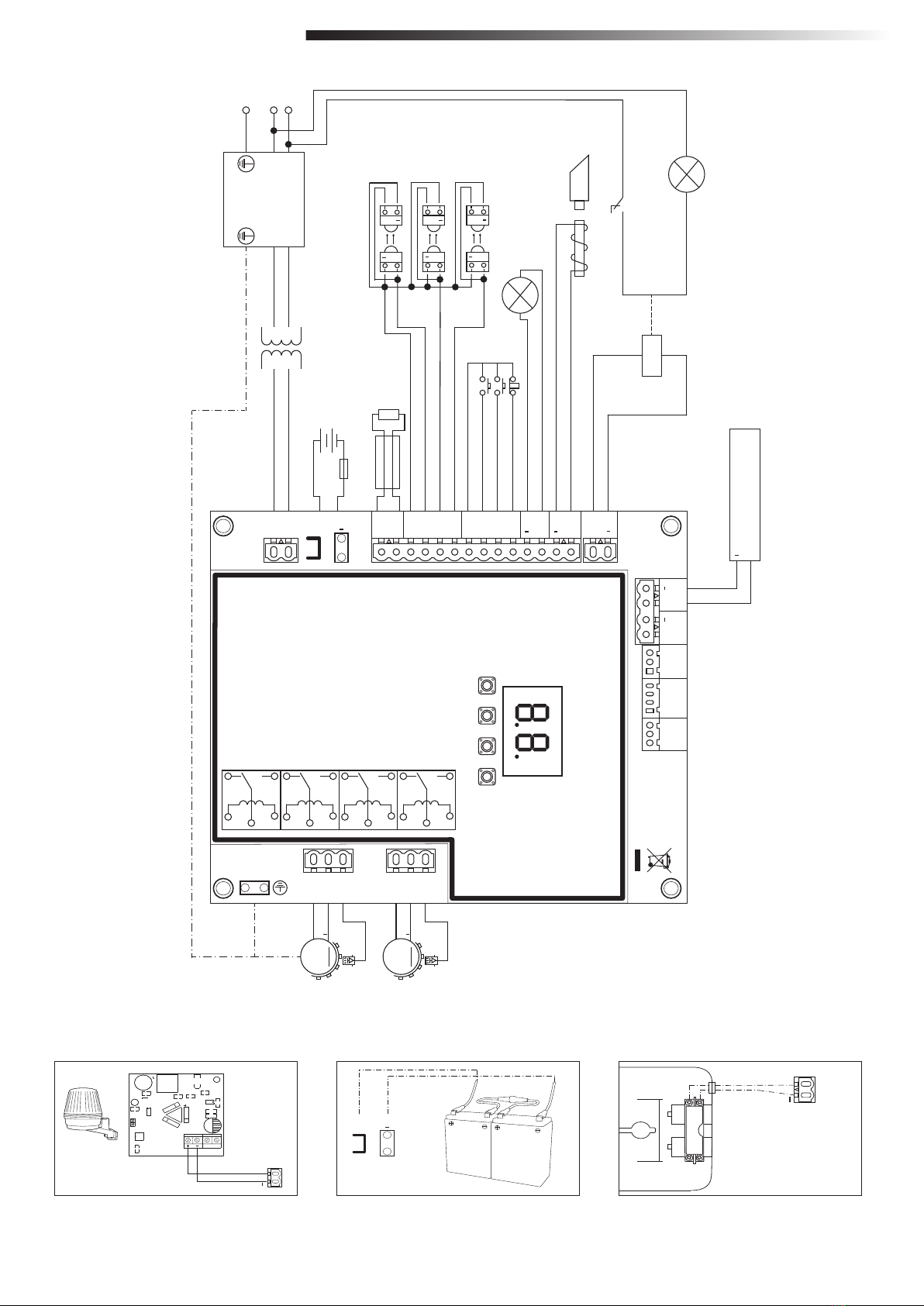
6. WIRING DIAGRAM......................................................................................................................................................................................................................................9
7. PROGRAMMING..............................................................................................................................................................................................................................................10
7.1 Display, Programming Buttons and Function Setting.........................................................................................................................................................................10
7.2 General Programming Overview..........................................................................................................................................................................................................10
7.3 Wing Movement Direction...................................................................................................................................................................................................................11
7.4 Basic Settings......................................................................................................................................................................................................................................11
7.4.1 Application Settings..................................................................................................................................................................................................................11
7.4.2 Direction Motor 1 Settings.........................................................................................................................................................................................................11
7.4.3 Direction Motor 2 Settings.........................................................................................................................................................................................................11
7.4.4 Limit Learning...........................................................................................................................................................................................................................11
7.5 Stand-by Mode....................................................................................................................................................................................................................................12
7.6 Programming and Erasing of Remote Controls, Radio Accessories and myQ Devices.......................................................................................................................13
7.7 Advanced Settings..............................................................................................................................................................................................................................14
7.7.1 Overview Advanced Settings....................................................................................................................................................................................................14
7.7.2 Transmitter Settings.................................................................................................................................................................................................................14
7.7.3 Infrared Photocells Settings......................................................................................................................................................................................................14
7.7.4 Input Settings...........................................................................................................................................................................................................................14
7.7.5 Partial Opening Motor 1.............................................................................................................................................................................................................15
7.7.6 Delay Motor 2 in Open Direction..............................................................................................................................................................................................15
7.7.7 Delay Motor 1 in Close Direction..............................................................................................................................................................................................15
7.7.8 Timer to Close..........................................................................................................................................................................................................................15
7.7.9 Reversal Time after Impact.......................................................................................................................................................................................................15
7.7.10 E-Lock / Mag-Lock Settings.....................................................................................................................................................................................................15
7.7.10a Relief Motor 1 for E-Lock.......................................................................................................................................................................................................16
7.7.11 Flashing Light Settings...........................................................................................................................................................................................................16
7.7.11a Pre-Flashing................................................................................................................................................................................................................................16
7.7.12 Special Contact Settings.........................................................................................................................................................................................................16
7.7.13 Start Speed in Open and Close Directions.............................................................................................................................................................................16
7.7.14 Maintenance Counter...............................................................................................................................................................................................................16
7.8 Factory Default Settings....................................................................................................................................................................................................................17
7.9 Finish and Exit...................................................................................................................................................................................................................................17
8. BATTERY BACKUP....................................................................................................................................................................................................................................17
9. ERROR CODES........................................................................................................................................................................................................................................17
10. TECHNICAL DATA....................................................................................................................................................................................................................................18
11. MAINTENANCE.......................................................................................................................................................................................................................................19
12. DISPOSAL.........................................................................................................................................................................................................................................19
13. WARRANTY.........................................................................................................................................................................................................................................19
14. DECLARATION OF CONFORMITY............................................................................................................................................................................................................19

2
About this Manual – Original Manual
These instructions are the original operating instructions according the machinery directive 2006/42 EC. The instruction manual must be read carefully to understand
important product information. Pay attention to the safety and warning notices. Keep the manual in safe place for future reference and to make it available to all persons
for inspection, service, maintenance and repair. After installation pass the complete documentation to the responsible person/owner.
Qualication of a competent installer
Only correct installation and maintenance by a competent installer (specialist) / competent company, in accordance with the instructions, must understand and ensure the
safe and intended function of the installation. Specialist is, who on the basis of their technical training and experience, has sufcient knowledge in the eld of powered
gates and moreover is familiar with relevant state occupational safety regulations and generally accepted rules of technology in such an extent that he is also able to
assess the safe working condition of powered gates according to EN 13241, 12604, 12453 (EN12635
The installer must understand the following:
Before installing the drive, check that the driven part is in good mechanical condition, opens and closes properly and correctly balanced where applicable
Before rst use and at least annually a specialist must inspect powered gate regarding their safe condition. After installation, the installer must ensure that the mecha-
nism is properly adjusted and that the protection system and any manual release function correctly (EU: EN 13241, EN12604, EN 12453, EN 12635; GB (UK, NI)
BS EN 13241, BS EN12604, BS EN 12453, BS EN12635). A regular maintenance, inspection must be carried out according to the standards. The installer must
instruct other users on the safe operation of the drive system.
After successful installation of the drive system, the responsible installer, in accordance with the EU: Machinery Directive 2006/42/EC; GB (UK, NI): Supply of Machinery
(Safety) Regulations 2008 SI 2008 No. 1597, must issue the EU: CE / GB (UK,NI): UK declaration of conformity for the gate system. The EU: CE / GB (UK,NI): UKCA
mark label must be attached to the gate system. This is also obligatory in the process of retrotting on a manually operated gate. Further, a handover pack and an inspec-
tion book must be completed.
Please read the operating instructions and especially the precautions. The following symbols are placed in front of instructions to avoid personal injury or damage to
property. Read these instructions carefully.
Warnings Symbols
The general warning symbol indicates a danger that can lead to injuries or death. In the text section, the general warning symbols are used as described below.
Intended use
The swing gate operator is exclusively designed and tested for the operation of smooth-running swing gates in the residential, non-commercial sector.
Specication for gates are dened under mechanical requirements according EU: EN12604 / GB (UK, NI): BS EN 12604.
The maximum permissible gate size and the maximum weight must not be exceeded. The gate must open and close smoothly by hand. Use the operator on gates which
comply with the applicable standards and guidelines. Regional conditions of wind loads must be taken into account when using door or gate panels EU: EN13241 / GB
(UK, NI): BS EN 13241. Observe the manufacturer‘s specications regarding the combination of door and operator. Possible hazards within the meaning of EU: EN13241
/ GB (UK, NI): BS EN 13241 are to be avoided by designing and installing the door/gate according to the relevant instructions. This gate mechanism must be installed and
operated in accordance with the appropriate safety rules.
Improper use
It is not intended for continuous operation and use in a commercial application.
The construction of the drive system is not designed for the operation of gates outside of manufacturers specication.
It is not permitted on gates that travel with incline/decline.
Any improper use of the drive system could increase the risk of accidents. The manufacturer assumes no liability for such usage. With this drive, automated gates must
comply with the current, valid international and country-specic/local standards, guidelines and regulations (EU: EN 13241, EN12604, EN 12453; GB (UK, NI) BS EN
13241, BS EN12604, BS EN 12453).
Only Chamberlain and approved accessories may be connected to the drive. Incorrect installation and/or failure to comply with the following instructions may result in
serious personal injury or damage to property.
Gate systems located in public areas and have only force limitation, can only be operated under full supervision.
Additional safety devises should be considered in accordance with EU: EN 12453; GB (UK, NI) BS EN 12453.
DANGER Symbol WARNING Symbol CAUTION Symbol ATTENTION Symbol
DANGER WARNING CAUTION ATTENTION
Indicates a danger that leads directly
to death or serious injuries.
Indicates a danger that can lead to
death or serious injuries.
Indicates a danger that can lead to
damage or destruction of the product.
Indicates a danger that can lead to
damage or destruction of the product.
1. SAFETY INSTRUCTIONS AND INTENDED USE

3
During operation, the gate should not under any circumstances obstruct public path ways and roads (public area).
When using tools and small parts to install or carry out repair work on a gate exercise caution and do not wear rings, watches or loose clothing.
To avoid serious personal injury due to entrapments, remove any locking device tted to the gate in order to prevent damage to the gate.
Installation and wiring must be in compliance with your local building and electrical installation regulations. Power cables must only be connected to a properly earthed
supply.
Disconnect electric power to the system before installation, maintenance, repairs or removing covers. A disconnecting device must be provided to the mains power supply
(permanently-wired installation) to guarantee all-pole disconnection (isolating switch or by a separate fuse). The repairs and electrical installations may be performed only
by an authorised electrician. Emergency Stop Button must be installed for emergency case based on the risk assessment.
Ensure that entrapment between the driven part and the surrounding xed parts due to the opening movement of the driven part is avoided by respecting the given safety
distances in accordance with the EU: EN 13241, EN12604, EN 12453, EN 12635; GB (UK, NI) BS EN 13241, BS EN12604, BS EN 12453, BS EN12635 and/or with
safety devices (e.g. safety edge).
Testing of the safety function of the drive system is recommended to be carried out at least once a month. Refer also to manufacturers instruction of the gate system
components.
After the installation a nal test of the full function of the system and the of the safety devices must be made and all users must be instructed in the function and operation
of the swing gate operator.
Gate systems must meet the force limitation according EU: EN 12453, EN 60335-2-103; GB (UK, NI) BS EN 12453, BS EN 60335-2-103.
Additional safety device (safety edge,.) must be considered in accordance to the standard by changes to the system.
It is important to make sure that the gate always runs smoothly. Gates which stick or jam must be repaired immediately. Employ a qualied technician to repair the
gate, never attempt to repair it yourself. This device is not intended for use by persons (including children) with restricted physical, sensory or mental abilities or lack of
experience or knowledge, unless they are supervised by a person responsible for their safety or have received instruction in how to use the device. If necessary, control
equipment MUST be mounted within sight of the gate and out of reach of children. Children should be supervised to ensure that they do not play with the device. Do not
allow children to operate push button(s) or remote(s). Misuse of the gate operator system can result in serious injury.
The warning signs should be placed in clearly visible locations.
The gate opener should ONLY be used if the user can see the entire gate area and is assured that it is free of obstacles and the gate operator is set correctly. No one may
pass through the gate area while it is moving. Children must not be allowed to play in the vicinity of the gate.
The full protection against potential crushing or entrapment must work immediately when the drive arms are installed.
There may be existing hazards on mechanical, electrical installation or the closing edges of the gate by crushing, impact points:
• Structural failure, leaf, hinges, xings, travel stops, wind load
• Crush, hinge area, under the gate, safety distance on xed object
• Electrical failure (Control – faults in safety systems)
• Impact, swept area, hold to run, force limitation, presence detection
Appropriate measures must be taken to ensure safe operation of the gate system according the standards.
Never start up a damaged drive.
Use the manual release only to disengage the drive and – if possible – ONLY when is gate closed. Operation of the emergency manual release can lead to uncontrolled
movements of the gate. The Timer-to-Close (TTC) feature, the myQ Smartphone Control app, are examples of unattended operation of the gate.
Any device or feature that allows the gate to close without being in the line of sight of the gate is considered as unattended open/close.
The Timer-to-Close (TTC) feature, the myQ Smartphone Control, and any other myQ devices can ONLY be activated when Chamberlains photo cells are installed (TTC
works only in close direction). The gate shall only be operated in the direct sight line to the gate.
IMPORTANT INFORMATION!
• This procedure is also required on private installations (new or retrotted to a manually operated gate).
This installation and operating manual must be retained by the user.
• The manufacturer accepts no liability/warranty claims resulting from use other than intended use and after the warranty expires.
• The legal remedy is the sole responsibility for all associated rights.
NOTE: Observe the installation and operating manual.
• Always monitor the function of the system and rectify the cause immediately in the event of a malfunction.
• Carry out an annual inspection of the system. Call a specialist.
• Safety distances must be respected between the gate leaf and the environment in accordance with related standards.
• The operator can be installed Only on stable and rigid gate leaves. Gate leaves must not bend or twist when opening and closing.
• Assure that the hinges of the gate leaf are installed and working correctly and not creating any obstacles.
• Installation of two operators on same door leaf is strictly prohibited.
1. SAFETY INSTRUCTIONS AND INTENDED USE

4
CHAA250EVC
Post Mounting
Bracket (2x)
13, 14 mm 6 mm
Screw and nut
(4x)
Cover (2x) Screw and
Washer (2x)
Strain relief
4 x M16
2 x M20
Grommets
(6x)
Hardstops (4x)
Screws + Washers (4x)
Gate Mounting
Bracket (2x)
Pin (2x) Circlip pin (2x)
Release Key
(4x)
Remote
Control (2x)
Primary unit with
Control Board
Secondary unit
Installation
Manual
1. Motor 1 with control board
2. Motor 2
3. Post bracket (concealed)
4. Gate bracket
5. Infrared photocells
6. Flashing lamp
4
52
3
4
5
6
3
1
2. DELIVERY SCOPE
3. TOOLS NEEDED
4. OVERVIEW OF GATE OPERATOR
Photocell

5
5.2 Determine the Position of the Post Bracket
1. Determine the A, B and C dimensions based on the opening angle provided in Table 1 to conrm the position where the post bracket will be mounted.
NOTE: All crushing points must be secured by an entrapment protection according to EU: EN 12453, EN 60335-2-103; GB (UK, NI): BS EN 12453, BS EN 60335-2-103.
CHAA250EVC
Example installation
CHAA250EVC
1.5 m 200 kg
2.0 m 150 kg
2.5 m 100 kg
Operator Arm Mounting
1. Attach the motor arm to the center of the opener from
the underside.
2. Secure the caps with the screw and washer.
175 mm265 mm
250 mm
280 mm
Picture 1
13 mm
54 mm
30 mm
159 mm
Ø 8.5 mm
96 mm
Ø 8.5 mm
100 mm
60 mm
20 mm
A B C
Opening angle mm
90° 150-300 390-540 0-300
120° 300-350 300-350 0-25
Table 1
min. 200 mm
20 mm
A
min. 420 mm
C
B
max. 120°
48.5 mm
Herewith you start mechanical installation of the gate operator.
5. MECHANICAL INSTALLATION
5.1 Dimensions of Gate and Operator

6
1. Using the post bracket as a reference, mark and drill the holes for the post bracket.
2. Attach the post bracket using the correct fastening material based on existing installation (building / material substance). Please consult the gate manufacturer.
3. The slots on the post bracket allow for alignment. When the post bracket is level tighten the nuts.
5.4 Operator Mounting and Travel Distance Adjustment
1. Align the holes on the operator to the post bracket holes and connect using the screws and nuts (see picture 3.a).
2. Connect the arm to the shaft of the motor unit (see picture 3.b). Do not mount plastic protection cover yet, if you plan to install operator hard stops.
3. Release the operator clutch with the release key (see picture 4 on page 7).
4. Bring gate leaf to the closed position.
NOTE: The system must operate with external gate or operator hard stops in both directions.
5.4.1 Installation with external gate hard stops: (gate hard stops already installed)
a. Position the gate bracket in the desired full closed position as shown in the picture 3.c. Temporarily secure it to the gate leaf and connect with operator arm considering
dimensions A, B and C from Table 1.
b. Manually open and close the gate to the required positions. Ensure the operator arm does not bind and gate is moving smoothly.
c. Make permanent connection of the gate bracket at chosen correct position.
5.4.2 Installation with operator hard stops: (no gate hard stops installed)
a. Position the gate bracket in the desired full closed position as shown in the picture 3.c. Temporarily secure it to the gate leaf (do not make permanent connection to
gate leaf yet to enable adjustments) and connect with operator arm considering dimensions A, B and C from Table 1.
b. Manually open and close the gate to the required positions. Ensure the operator arm does not bind and gate is moving smoothly.
c. Fix the operator hard stop for “close” position as close as possible to the arm (see picture 3.d).
Hold the gate leaf in the desired “closed” position and adjust position of the gate bracket, so that the arm pushes against hard stop in “close” position (see pictures 3.e and 3.f).
d. Make permanent connection of the gate bracket at chosen correct position.
e. Open the gate to the required “open” position and x the operator hard stop for “open” position as close as possible to the arm (see pictures 3.g and 3.h).
f. Mount the protection cover at the operator bottom (see picture 3.i).
4.3 A combination of operator and gate hard stops is allowed. Please use the respective set up procedures as described above.
5. Repeat the procedure for the unit on the opposite side.
5.3 Post Bracket Installation
NOTE: For brick or concrete posts please use correct dowels and screws. Please
maintain correct distance to the post edges.
For metal posts please consider the post thickness and weld or bolt the bracket
directly to post.
For timber posts please use correct screws and if required use reinforcement plates.
Caution: The fastened brackets must not loosen after installation and during operation.
Picture 2
3.a 3.b
13 mm
6 mm
3.c
5.MECHANICALINSTALLATION
Picture 3

7
INSTALLATION
5.5 Emergency Release Mechanism
To disengage the release mechanism remove the plastic cover, enter the key and turn it 90°.
Pull the clutch up (see picture 4). To re-engage the release meachanism, push the clutch down and turn the key 90°.
3.d
3.h
3.f
3.g
3.e
max. 120°
3.i
Picture 4
4.a 4.b

8
The control board is already pre-installed in the Primary unit and pre-wired to the terminals of Motor 1.
To gain access to the control board in the Primary unit release the 2 screws on the sides of the cover and 2 screws on the back of the Primary unit (see picture 5).
The terminals for wiring accessories are directly accessible. To get access to the programming buttons remove the transparent plastic cover and place it back once pro-
gramming is nished (see picture 6). Remove the cover of the Secondary unit same way as with Primary unit to gain access to the Motor wiring terminal (see picture 7).
5.7 Power Wiring
Mains power wiring must be done by a certied electrician specialist.
Motor 2 Connection
NOTE: The operator wired to the MOTOR 2 terminal will always open last and close rst.
Consider this for Basic and Advanced Settings (see Programming section).
1. Connect the extension cable (not provided) to the wiring terminals of the Secondary
unit (see picture 7).
Note the cable colors of the Secondary motor to match them on the control board wiring
terminal for MOTOR 2.
2. Feed the Secondary motor extension cable through one of the cable glands at the bottom
of the Primary unit (see picture 8). Ensure to use the side of the motor where the arm cannot cut the cables
during opening or closing movement.
3. Connect Secondary motor cables to the MOTOR 2 terminals as follows: red cable to RED terminal, green cable to GRN terminal , white cable to WHT terminal on
control board.
5.6 Control Board Installation and Motor Wiring
INSTALLATION
Motor 1 Connection
NOTE: The operator wired to the MOTOR 1 terminal will always open rst and close last.
Consider this for Basic and Advanced Settings (see Programming section).
Primary unit is already pre-wired to MOTOR 1 terminals. No extra steps required for Motor 1 wiring.
Per default settings, the Primary unit is considered installed on the left (when looking from inside out), and the Secondary unit on the right.
In case the Primary unit is installed on the right, and the Secondary unit on the left, change the settings of functions «d1» and «d2».
Primary unitRemoving CoverPicture 5 Picture 6 Secondary unit
Extension cable
(not supplied)
Picture 7
Wiring terminal
Picture 8
Picture 9
Congratulations! Herewith the mechanical installation of your gate operator is
nished. Please proceed with Programming and Basic Settings to be able to
start operation.

9
MOTOR 2
WHT GRN RED WHT GRN RED
MOTOR 1
+M
+M
BAT+
BAT-
24V
BATTERY
POW
24V
SPEC
24VDC SYNC STBY UART LIMIT-SW
+
+
+
+
+
E-LK
FLA
COMMANDIR SENSOREDGE24V BAT
8.2K
SAFETY EDGE
+
+
+
+
+
+
NC
NO
NO
Stop
Fully Open
Partial Open
LAMP 1
FLASH LAMP
SE SE GND GNDIR3 IN3 IN2 IN1IR2 IR1
L L
NN
PE
AC 230V IN
CTRL GND 12V - TX RX 5V OP - CL
+
24V external accessories
Examples: external receiver
+
PE
220-240V/50/60Hz
28V AC
EXAMPLE
EXAMPLE
S P +-
Fuse
E-LOCK / MAG LOCK
IR 1IR 2IR 3
E-LOCK: 600024
24 V CC
15W
2
1
E-LK
JP1
4321
Power
Signal
4
3
FLA
+
+
FLASH-LAMP: FLA1-LED 24V BAT: 490EV
1 1
BAT+
BAT-
24V BAT
+
SYNC, STBY, UART, LIMIT-SW
connectors are not used for AA units
MOTOR 2
WHT GRN RED WHT GRN RED
MOTOR 1
+
M
+
M
BAT+
BAT-
24V
BATTERY
POW
24V
SPEC
24VDC SYNC STBY UART LIMIT-SW
+
+
+
+
+
E-LK
FLA
COMMANDIR SENSOREDGE24V BAT
8.2K
SAFETY EDGE
+
+
+
+
+
+
NC
NO
NO
Stop
Fully Open
Partial Open
LAMP 1
FLASH LAMP
SE SE GND GNDIR3 IN3 IN2 IN1IR2 IR1
L L
NN
PE
AC 230V IN
CTRL GND 12V - TX RX 5V OP - CL
+
24V external accessories
Examples: external receiver
+
PE
220-240V/50/60Hz
28V AC
EXAMPLE
EXAMPLE
S P
+
-
Fuse
E-LOCK / MAG LOCK
IR 1IR 2IR 3
E-LOCK: 600024
24 V CC
15W
2
1
E-LK
JP1
4321
Power
Signal
4
3
FLA
+
+
FLASH-LAMP: FLA1-LED 24V BAT: 490EV
1 1
BAT+
BAT-
24V BAT
+
6. WIRING DIAGRAM

10
P +S
P +S
P +S
P +S
P +S
P +S
I
I
I
I
I
I
I
I
I
I
I
I
5 sec.
5 sec.
EXIT
Go to stand by
mode
or
or
7.1 Display, Programming Buttons and Function Setting
Function setting - programming mode
7.2 General Programming Overview
General setup:
Programming buttons function (4 buttons):
Button Function
Sprogram / delete remote controls and specic functions
Penter programming mode, select function and save
+/- Navigate through the menu and change the value on display
Function and programmed values are shown on LED display.
LED display shows following values after control board is powered:
The programming is divided in 2 sections:
1. Basic Settings (Page 11)
2. Advanced Settings (Page 14)
After Basic Settings are done, following parameters will be learned automatically
during Learning phase:
1. Travel length from FULL CLOSED to FULL OPEN position.
2. Opening and closing force for each motor.
NOTE:
• Basic Settings and Learning phase must be completed to enable operation.
• After the Learning phase and Programming are nished the operator will work
as per default settings.
• Advanced Settings cannot be accessed if Basic Settings and Learning phase
are not completed.
• Before making the programming ensure that the relevant safety devices
are connected.
1. Press and hold “P” button for 5 seconds to enter the menu. “AP” on the display
indicates the rst available function in menu.
2. Use “+“ and “–” buttons to navigate between the functions.
3. Press “P” button to select the required function.
4. The default setting or previously programmed value will appear. This will be
indicated by ashing of value on display.
5. Use “+” or “–“ buttons to select the required value. Press “P” button to conrm
selection.
6. The programmed function is shown on display.
7. To change the setting of another function, repeat the sequence from the points
#2 to #6
8. To exit to the Function menu, press “P” button for 5 seconds, then the board will
go in Stand-by mode.
If “P” button is not pressed to conrm new value setting, new settings will be saved
after 3 minutes and programming will exit menu and return into Stand-by mode.
NOTE: To operate the gate or execute any command, setting menu must be
nished by pressing the “P” button for 5 seconds, or by selecting FE Function, or
waiting 3 minutes for automatic exit and return into Stand-by mode.
Control board is pre-programmed to relevant application (see
below under “Application” and “Stand-by Mode” for status
description).
“E0”, in case the control board has not been programmed yet
or reset by function “Factory Default”. From this status, an
Input or transmitter command will be always ignored.
Example only
P +S
2 digit LED display
LED spot
7. PROGRAMMING
Herewith you start programming of your gate operator.

11
7.3 Wing Movement Direction
7.4 Basic Settings
Before programming, move the gate manually in the middle position and re-engage
release mechanism (see page 7).
Press and hold the “–“ button on the control board and ensure that the motors are
moving in CLOSE direction. If correct, immediately let go of the “-“ button and gate stops.
If motors are moving in OPEN direction, go to the functions “d1“ and “d2” and
change the direction settings.
Once CLOSE direction is set correctly, leave the gate in the middle position. The
operator is ready for the Learning phase.
Note: gate can be moved with “+“ and “-“ buttons prior to nal settings if required.
Press and hold the “+“ button on the control board to move the gate into OPEN
position. When button is released operator stops.
Press and hold the “–“ button on the control board to move the gate into CLOSE
position. When button is released operator stops.
Application function shown on display.
This function is already pre-set at factory at value 03.
More settings available on demand:
LED Function
Basic Settings (mandatory)
AP Application
d1 Direction Motor 1
d2 Direction Motor 2
LL Limit Learning Phase
Basic Settings Overview
7.4.1 Application Settings
No application selected
Swing gate, one motor for CHAA250 application
Swing gate, two motors for CHAA250 application (default)
Direction Motor 1 function shown on display
Denes movement direction of the Motor 1.
Direction Motor 2 function shown on display.
Denes movement direction of the Motor 2. Not available for “one motor”
application.
7.4.2 Direction Motor 1 Settings
7.4.3 Direction Motor 2 Settings
Motor 1 is moving in closing direction, when installed on the righ-
hand side.
Motor 1 is moving in closing direction, when installed on the left-
hand side (default)
Motor 2 is moving in closing direction, when installed on the right-
hand side (default)
Motor 2 is moving in closing direction, when installed on the left-
hand side
Available Learning methods:
Before starting a Learning phase ensure that:
1. Other Basic Settings are completed
2. Internal / external hard stops are installed (for swing gates)
3. First movement will be in CLOSE direction.
1. Press and hold “+and –“ buttons for 2 seconds.
2. Automatic learning process starts. LL will ash on the display during complete
process.
3. Wing 2 moves in CLOSE direction until the hard stop is reached, and stops.
4. Wing 1 moves in CLOSE direction until the hard stop is reached, and stops for
2 seconds. Then Wing 1 starts in OPEN direction until the hard stop is reached.
5. Wing 2 moves in OPEN direction until hard stop is reached, stops for 2 seconds
and then moves in CLOSE direction until hard stop is reached, and stops.
6. Wing 1 moves in CLOSE direction until hard stop is reached, and stops.
7. Standard Learning phase is nished. LL will appear on display and board will
return in stand-by mode after 3 seconds.
Standard Learning Mode (Automatic)
7.4.4 Limit Learning
P +S
2 sec.
I
I
I
I
I
I
3 sec.
P +S
Values 01, 04 und 05 are not suitable for CHAA250 application and shall not be chosen. NOTE: In single motor application, “Wing 2” actions are not used.
Following settings are done during Standard Learning Mode:
1. Travel length from FULL CLOSED to FULL OPEN position.
2. Opening and closing force for each motor.
3. 15% of total travel in both directions is assigned for Soft Stop.
4. Wing delay in opening and closing position is 2 seconds. Shall you need to
change the delay please go to Advanced Settings: Delay Motor 2 (d0) and
Delay Motor 1 (dC).
7. PROGRAMMING

12
NOTE: To stop Learning phase press “S” button. The Learning process will be
interrupted, “LE” will ash on LED display. After 5 seconds “LL” will appear on
display indicating readiness to start Learning phase again.
If Learning process was not completed, it needs to be re-done.
ATTENTION: Learning phase must be completed to enable operation.
P +S
I
I
I
I
I
I
5 sec.
7.5 Stand-by Mode
After the control board is powered on and programming is nished, the LED display
lights completely for 2 seconds and goes into the stand-by mode. During Stand-by
mode the LED display shows current gate status.
Herewith the Basic Settings are completed. You can leave Programming
and operate your gate or proceed with Advanced Settings.
Two motors
(default) One motor
Motor is opening, upper section of the display
ashes.
I
I
I
I
I
I
Motor stops at the opening position, upper
section of the display is on.
Motor is closing, lower section of the display
ashes.
I
I
I
I
I
I
Motor stops at the closed position, lower
section of the display is on.
Motor stops in the middle, middle of the
display is on.
7. PROGRAMMING

13
7.6 Programming and Erasing of Remote Controls, Radio Accessories and myQ Devices
Program remote control devices (transmitters and wireless wall controls):
NOTE: the remote controls delivered with the operator are already factory pre-
learned to the operator (top button near the LED) and do not require extra pro-
gramming.
1. Press and release “S” button. An LED spot turns ON in the display. The ope-
rator will stay in Radio programming mode for 3 minutes. Any radio accessory
device can be learned within rst 30 seconds. During the remaining 2.5 minutes
only myQ devices can be learned.
2. Chose the required button on your transmitter and hold it until the dot in the
display turns off.
To program a new remote control repeat the sequence.
To program a wireless keypad, please follow the respective manual of the
accessory.
Programming Transmitter in Partial opening
Press and hold “S“ and “+“ buttons at the same time, until the LED spot starts as-
hing. Press and hold the desired free button on transmitter to program the Partial
Opening Mode.
The LED spot turns off when the programming is nished. If there is a light connec-
ted to SPEC contact it will ash once.
Program myQ gateway (830REV-01):
1. Connect
Connect ethernet cable (1) provided with gateway to router (2).Use the plug valid
for your country ( not all models). Connect power (3) to the internet gateway (4).
When the internet gateway connects to the internet, the green light (5) will stop
blinking and will light solid. A connected set of IRs is mandatory for myQ operation.
2. Create an account
Download the free myQ App from App Store or Google Play Store and create an
account. If you already have an account, use your username and password.
3. Register the internet gateway
Enter the Serial Number located on the bottom of the internet gateway when
prompted.
4. Add myQ devices
To add your gate operator to the registered gateway follow the instructions on the
app. When adding a new myQ capable gate operator press and release “S” button
on operator control board. An LED spot turns ON in the control board display.
Note: After you add a device, the blue light on the internet gateway will appear and
stay on. Press “S” button on the operator control board to exit the radio programm-
ing mode.
5. Test
After having installed and registered correctly you may now test the following
features: open or close the gate, request status GATE OPEN or GATE CLOSED.
For more functions see www.chamberlain.eu
Erase radio control devices (transmitters, wireless wall controls, wireless
keypads):
Press and hold “S” button for > 6 seconds. All radio control devices (transmitters,
wall controls, keypads) are erased. The LED spot in the display turns OFF. Note: It
is not possible to erase radio control devices individually.
Erase myQ devices:
1. Erase remote control devices rst as indicated above.
2. Within next 6 seconds press and hold “S” button. An LED spot turns ON in the
display.
3. Press and hold “S” button for > 6 seconds. All myQ devices are erased. The
LED spot in the display turns OFF.
NOTE: It is not possible to erase myQ devices individually. It is not possible to
erase myQ devices only.
1
2
3
4
5
P +S
I
I
I
EXIT
6 sec.
7. PROGRAMMING
P +S
I
I
I
EXIT

14
LED Function
tr Transmitter
r1 IR1 photocell
r2 IR2 photocell
r3 IR3 photocell
i1 Input 1 command
i2 Input 2 command
i3 Input 3 command
Pd Partial Opening Motor 1 only
d0 Delay Motor 2 in OPEN
dC Delay Motor 1 in CLOSE
tC Timer To Close (TTC)
rt Reversal time after impact
EL E-lock
rb Relief Motor 1 for E-lock
LED Function
FL Flashing Light
PF Pre-Flashing
SP Special contact
St START Speed in OPEN and CLOSE
Cn Maintenance counter
Fd Factory default
FE Finish and Exit
7.7 Advanced Settings
7.7.2 Transmitter Settings
Transmitter function denes how Transmitter commands are working.
Note: Under settings “01”, “02” and “03”, TTC timer will be overridden
by a transmitter command and will CLOSE the gate.
Under setting “04”, active TTC timer countdown will be re-set to start
again by Transmitter command.
Residential Mode: Open – Close – Open
Standard Mode: Open – Stop – Close – Stop – Open (Default)
Automatic with Stop Mode: Open – Stop – Close – Open
Car Park Mode: Open, to complete Open position. Additional com-
mand during the opening will be ignored 7.7.4 Input Settings
Inputs function denes the way Input commands from external accessories are
executed. Each of the 3 Inputs can be programmed individually.
NOTE: Under settings “01”, “02” and “03”, TTC timer will be overridden by an Input
command and will CLOSE the gate. Under setting “06”, active TTC timer count-
down will be re-set to start again by an Input command
IR active on CLOSE movement. If IR beam is obstructed, gate re-
verses in complete OPEN position (Default).
IR active on OPEN movement. If IR beam is obstructed gate stops.
When obstruction disappears the gate continues to OPEN.
IR is active on OPEN and CLOSE movement. If IR beam is obst-
ructed on CLOSE movement, gate stops and after the obstruction
disappears gate reverses in complete OPEN position. If IR beam
is obstructed on OPEN movement, gate stops. When obstruction
disappears the gate continues to OPEN.
IR active on CLOSE movement. If IR beam is obstructed, gate re-
verses in complete OPEN position. The activated TTC function will
be overridden 2 seconds after the beam obstruction is eliminated
and will start CLOSE movement not waiting till the end of TTC time
end.
7.7.3 Infrared Photocells Settings
IR functions dene functioning mode of Infrared Photocells (IR).
IRs will be auto-learned when installed.
Each of the 3 IR sets can be programmed individually.
NOTE: Depending on the chosen settings the Partial Opening inputs or Remote
Controls commands will not be executed in both OPEN or CLOSE direction if the
IR beam is obstructed. If IRs are removed, the control board power must be turned
OFF/ON for two times to unlearn.
For check and maintenance of the photocells see the manual of the photocells.
7. PROGRAMMING
Herewith you start with Advanced Settings.

15
Open – Close – Open
Open – Stop – Close – Stop – Open (Default)
Open – Stop – Close – Open
Partial opening Motor 1 only
STOP (NC contact)
no delay (both wings start in the same time)
1 second
2 seconds (Default)
... ... seconds
20 seconds
7.7.7 Delay Motor 1 in Close Direction
Delay Motor 1 in CLOSE direction function denes time delay for Motor 1 in
CLOSE direction. Not available for the single motor application.
Not executed during reversal or after IR beam interruption in both directions.
1. Press and hold “S“ and “+“ buttons at the same time, until the LED spot starts
ashing.
2. Press and hold the desired free button on transmitter to program the Partial
Opening Mode.
3. The LED spot turns off when the programming is nished. If there is a light
connected to SPEC contact it will ash once.
TTC not active (Default)
10 seconds
20 seconds
30 seconds
45 seconds
1 minute
1.5 minutes
2 minutes
3 minutes
5 minutes
7.7.8 Timer To Close
Timer to close (TTC) function enables automatic closing of the gate from a comple-
te OPEN position after a pre-set period of time. Minimum one pair of Chamberlain
Infrared Photocells (IR) has to be installed to monitor closing movement to enable
TTC operation. TTC will not work if IR are protecting opening movement only.
TTC will also work with activated partial opening. If TTC function is active, timer is
counting down, and the IR beams are interrupted, the TTC timer shall re-start.
2 seconds reversal and Stop
Reversal back up to the end limit position (Default)
During Closing movement, upon impact gate reverses up to Open
position. During Opening movement, upon impact gate reverses for
2 seconds and stops
7.7.9 Reversal Time after Impact
Reversal time after impact function denes reversal behaviour after obstacle obst-
ruction during closing or opening movement. This reversal behaviour is valid both
for motor force detection and safety edge application.
50% opening travel
75% opening travel (default)
100% opening travel
7.7.5 Partial Opening Motor 1
Partial opening Motor 1 only gives you the ability to open active leaf to a pre-set
value only.
NOTE: Pd command will work starting from Close limit position and during closing
movement. If a Pd command is executed from a complete OPEN position, the gate
will close.
An Open or transmitter command will always override the Pd command.
no delay (both wings start opening at the same time)
1 second
2 seconds (Default)
3 seconds
4 seconds
7.7.6 Delay Motor 2 in Open Direction
Delay Motor 2 in OPEN direction function denes time delay for Motor 2 in OPEN
direction. Not available for single motor application.
Not executed during reversal or after IR beam interruption in both directions.
7. PROGRAMMING
e-lock/mag-lock not installed (Default)
e-lock active for 1 second prior to Motor 1 start in Open direction
e-lock active for 2 seconds prior to Motor 1 start in Open direction
Magnetic lock, constantly active at gate CLOSED or constantly
inactive during OPEN and CLOSE movement, gate OPEN or STOP
position. Magnetic lock will be deactivated in Battery Back-up mode.
7.7.10 E-Lock / Mag-Lock Settings
E-Lock function denes e-lock/mag-lock behaviour.
24VDC – 500mA e-lock or mag-lock can be connected.

16
7.7.13 Start Speed in Open and Close Directions
Start Speed function allows switching the Soft-Start in OPEN and CLOSE directi-
ons ON and OFF.
deactivated (Default)
Soft Start active: motors will accelerate gradually until they reach
standard speed.
no ashing lamp installed (Default)
continuous 24V supply - for ashing lamp with own control board
(FLA1-LED)
interrupted 24V supply - for ashing lamp without own control board
7.7.11 Flashing Light Settings
Flashing Light function allows to select which type of Flashing Lamp is connected.
24VDC- max 500 mA Flashing lamp (FLA1-LED) can be connected.
7.7.11a Pre-Flashing
Pre-Flashing function denes time interval of pre-ashing of the ashing lamp prior
to gate movement. Function not active if Flashing Lamp (FL) Function is set to “00”.
no pre-ashing (Default)
1 second
2 seconds
7.7.12 Special Contact Settings
Special Contact Function denes relay activation time.
A 24V max 500mA relay can be connected to manage other devices, e.g. courtesy
light. The time set here will also control countdown for myQ remote light.
no activation (Default)
15 seconds
30 seconds
45 seconds
1 minute
1.5 minutes
2 minutes
3 minutes
4 minutes
5 minutes
7.7.14 Maintenance Counter
Maintenance Counter function allows to set maintenance interval in cycles.
4 seconds pre-ashing of the Flashing Lamp will be a signal the interval is reached.
If PF Function (Pre-Flashing) is active then 4 second pre-ashing will be added
to the set time. To reset counter after maintenance is done, it will be enough to
program the cycles one more time.
no counter (Default)
1000 cycles
2000 cycles
... ... cycles
20000 cycles
deactivated (Default)
1 second activated
2 seconds activated
7.7.10a Relief Motor 1 for E-Lock
Relief Motor 1 for e-lock function enables to briey push Motor 1 in CLOSE direc-
tion before engaging e-lock to relieve excess pressure on e-lock.
Not available if EL Function is set to “00” or “03” (e-lock not connected / mag- lock
connected).
3 seconds
4 seconds
5 seconds
7. PROGRAMMING

17
7. PROGRAMMING
8. BATTERY BACKUP
Battery Back-Up Mode
2 Optional 12V, 2.2Ah lead batteries SKU 490EV (optional, not included) can be mounted inside the E-Box. Follow the manual of SKU 490EV for exact installation proce-
dure. A Flashing lamp (if mounted) will ash 2 seconds every 10 minutes indicating BBU mode and power loss. Control board will switch into stand-by mode with active
radio receiver accepting radio control device commands only. All other accessories and peripheral devices will not be functioning.
When in Battery Back-up mode, myQ Smartphone Control and wireless myQ devices will be disabled. Full charged battery capacity shall support up to ~20 cycles at a
rate of 2 per hour. After 24 hours of BBU mode the battery shall provide power for 1 complete opening and closing cycle. Please note that only the specied battery can
be use. Use of any other battery leads to loss of warranty and loss of liability of Chamberlain for any related damages resulting from use of unspecied batteries.
7.8 Factory Default
7.9 Finish and Exit
Factory default function resets control board to the original factory set-ups. All set-
tings, including limit settings, will be erased. LED display will show “E0”. Program-
med remote controls will remain learned. If Remote control accessories need to be
erased refer to the respective Radio Controls Programming section of this manual.
To exit the programming phase and save all changes,
move to FE function and press “P” button. The control board will go into Stand-by
mode and is ready to work.
There are also other ways to exit the programming and save settings:
• Press and hold “P” button for 5 seconds
• Wait 3 minutes after the last changes in the programming for automatic exit
no reset (Default)
reset to the factory default settings
LED Error
code Issue Possible reason Solution
E0 Press transmitter, but no gate
movement AP is set to 00 Check if AP is set to 00. If yes, change to correct application setting.
E1 Gate do not close, but can
open.
1) IR1 is not connected, or wire is cut. 1) Check if IR1 is not connected, or wire is cut.
2) IR1 wire is shorted out or reverse connected. 2) Check IR1 connection, change wires if needed.
3) IR1 is not aligned or blocked for a moment. 3) Align IR transmitter and receiver to make sure both LED is on,
instead of blinking. Make sure there is nothing hanging on gate that
may cause IR blocking.
E2 Gate can close when it is at
open limit, but cannot open
when it‘s at close limit.
1) IR2 is not connected, or wire is cut. 1) Check if IR2 is not connected, or wire is cut.
2) IR2 wire is shorted out or reverse connected. 2) Check IR2 connection, change wires if needed.
3) IR2 is not aligned or blocked for a moment. 3) Align IR transmitter and receiver to make sure both LED is on,
instead of blinking. Make sure there is nothing blocking the IR.
E3 Press transmitter, but no gate
movement.
1) IR3 is not connected, or wire is cut. 1) Check if IR3 is not connected, or wire is cut.
2) IR3 wire is shorted out or reverse connected. 2) Check IR3 connection, change wires if needed.
3) IR3 is not aligned or blocked for a moment. 3) Align IR transmitter and receiver to make sure both LED is on,
instead of blinking. Make sure there is nothing hanging on gate that
may cause IR blocking in short time.
E4 Press transmitter, but no gate
movement.
1) Safety edge is not connected with 8.2kohm
resistor. 1) Check if the 8.2 kOhm safety edge is properly connected or if the
8.2 kOhm resistor is installed.
2) Safety edge wire is shorted out. 2) Check safety edge wires and replace wire if needed.
3) Safety edge is pressed. 3) Check if safety edge is pressed.
9. ERROR CODES

18
LED Error
code Issue Possible reason Solution
E5 Press transmitter, but no gate
movement.
1) STOP swtich is open. 1) Check if STOP switch is open or damaged.
2) STOP switch is not connected. 2) Check if STOP switch is disconnected. If yes, then reconnect
STOP switch or change the respective Input setting to other value.
E7 Press transmitter, but no gate
movement. Control board amplier for Motor 1 fail. Switch off power for 20 seconds and reset to check if control board
recovers. If not, change control board.
E8 Press transmitter, but no gate
movement. Control board amplier for Motor 2 fail. Switch off power for 20 seconds and reset to check if control board
recovers. If not, change control board.
E9 Press transmitter, but no gate
movement. Control board memory mistake. Switch off power for 20 seconds and reset to check if control board
recovers. If not, change control board.
F1 Motor 1 stop and reverse
during open or close. Motor 1 is blocked. Check and remove obstruction. Clean gate.
F2 Motor 2 stop and reverse
during open or close. Motor 2 is blocked. Check and remove obstruction. Clean gate.
F3 Motor 1 stop and reverse
during open or close. Motor 1 stall or speed sensor is damaged. Check if motor 1 stalled or speed sensor is damaged.
F4 Motor 2 stop and reverse
during open or close. Motor 2 stall or speed sensor is damaged. Check if motor 2 stalled or speed sensor is damaged.
F5 Press transmitter, but motor
has no action. Radio module fail. Switch off power for 20 seconds and reset to check if control board
recovers. If not, change control board.
F6 Gate reverse during closing. Low battery power. Charge battery.
F7 Press transmitter, but no gate
movement. Control board damaged. Switch off power for 20 seconds and reset to check if control board
recovers. If not, change control board.
F9 Press transmitter or push
button, but motor has no
action. AP menu is reset to factory default. Relearn limits.
LE Motor stops suddenly. Press C button during limit learning. Relearn limits.
9. ERROR CODES
CHAA250EVC
Input Voltage VAC 220-240
Input frequency Hz 50/60
Motor Voltage VDC 24V
Standby consumption
(without accessories) W 3.2
Motor Rated Power W 100W (CHAA250-24P)
50W (CHAA250-24S)
Rated Load Nm 72,4
Maximum Torque Nm 200
Cycles per hour 5
Max. cyles per day 20
Max. wing width / weight m / kg
1.5m / 200kg
2.0m / 150kg
2.5m / 100kg
Max. opening angle 120°
Time to open to 90° s 13-15
End Limit System Encoder with hard stops
Operating Radio Frequency
Sending Power
MHz
RX 433MHz
(433.30MHz, 433.92MHz, 434.54MHz)
RX 868MHz
(868.30MHz, 868.95MHz,
869.85MHz)
TX 865.125MHz, 865.829MHz,
866.587MHz
<10mW
Code Security+ 2.0
Max. nr of remotes 180
Max. nr. of keypads 4
Max. nr. of myQ devices 16
CHAA250EVC
External accessory power 24VDC - max. 500mA
Flahing lamp connector 24VDC - max. 500mA
E-Lock /Magnetic lock conenctor 24VDC - max. 500mA
External relay 24VDC - max. 500mA
Safety edge 8,2 kOhm
Max. nr. of IRs 3
Max. nr. of external inputs 3
Battery back-up unit 2 x 12V, 2.2Ah batteries model 490EV
Ingress Protection Motor IP 44
Noise Level dB < 70 db(A)
Working temperature °C -20°C to +55°C
Weight (kit) Kg 20
Transmitter Frequency
TX4REV-F
868MHz (868.30MHz, 868.95MHz,
869.85MHz)
Sending power <10mW
Battery CR2032 3V
10. TECHNICAL DATA

19
11. MAINTENANCE
Battery of the remote control:
The batteries in the remote have an extremely long life. If the transmission range decreases, the batteries must be replaced. Batteries are not covered by the guarantee.
Please observe the following instructions for battery:
Batteries should not be treated as household waste. All consumers are required by law to dispose of batteries properly at the designated collection points. Never recharge
batteries that are not meant to be recharged.
Danger of explosion!
Keep batteries away from children, do not short-circuit them or take them apart. See a doctor immediately, if a battery is swallowed. If necessary, clean contacts on battery
and devices before loading. Remove at batteries from the device immediately!
Increased risk of leakage!
Never expose batteries to excessive heat such as sunshine, re or similar!
There is increased risk of leakage!
Avoid contact with skin, eyes and mouth. Rinse the parts affected by battery acid with plenty of cold water and consult a doctor immediately. Use only batteries of the
same type. Remove the batteries if the device is not being used for a long time.
Replacing battery:
To replace battery, turn remote control around and open the case with a screwdriver. Lift cover and lift control board below. Slide battery to one side and remove. Watch
polarity of battery! Assemble again from in reverse direction.
ATTENTION!
Danger of explosion if battery is replaced improperly. Replacement only by identical or equivalent type (CR2032) 3V.
The drive mechanism is maintenance free. Check the gate ttings and the drive mechanism at regular intervals (monthly) are securely xed. Release the drive and check
that the gate functions properly. Unless the gate runs smoothly it will not operate correctly with the drive mechanism. The drive cannot eliminate the problems caused by a
gate that does not work correctly.
These settings must be checked and undertaken properly during the installation of the opener! Due to weathering, minor changes can occur during operation of the ope-
ner that need to be addressed by a new setting. This can particularly happen in the rst year of operation. Follow the instructions for setting travel limits and force (refer to
section Limit Learning Phase, pages 11 and 12) carefully and re-check the automatic safety reverse after each resetting!
IMPORTANT Notice! Follow the safety notices. See “Safety instructions” (pages 2 and 3). The sequence described in the “installation” section, but in opposite order.
Ignore the setup instructions.
Your statutory rights are not affected by this manufacturer‘s warranty. Please see www.chamberlain.eu for terms of warranty.
Our electrical and electronic equipment may not be disposed of with household waste and must be disposed of after use properly in accordance with WEEE Direc-
tive EU: 2012/19/EU; GB UK(NI): SI 2012 nr. 19 on waste electrical and electronic equipment in order to ensure that materials are recycled. Collecting waste elect-
rical equipment separately means environmentally-friendly disposal and is completely free of charge for the consumer. WEEE reg. no. in Germany: DE66256568.
Any waste packaging left over with the end consumer must be collected separately from mixed waste, in accordance with the Directive. Packaging may not be disposed
of with household waste, organic waste or in nature. Packaging material must be separated according to its material and disposed of in the recycling containers provided
and in certain council recycling bins.
Replace Batteries in The Remote Control
The drive mechanism
Limit switch adjustment and force regulation
Disassembly
Our batteries are marketed in compliance with the law. The ‘crossed-out waste bin’ indicates that batteries may not be disposed of with household waste. Batteries
included in the product (technical data). In order to avoid causing harm to the environment or people’s health, used batteries must be returned for regulated dis-
posal at council recycling centres or via retail outlets, as is prescribed by law. Batteries may only be brought for disposal once fully discharged and, in the case of lithium
batteries, with their terminals taped over. The batteries can be easily removed from our equipment for disposal. Registration number in Germany: 21002670.
The manual consists of these operating instructions and the declaration of conformity.
The radio equipment type (TX4REV-F) is in compliance with Directive 2014/53/EU and for UK with Radio Equipment Regulation SI 2017 No. 1209.
The full text of the EU declaration of conformity is available at the following internet address: https://doc.chamberlain.de
CAUTION
Risk of explosion if the battery is replaced by an incorrect type.
Do not ingest battery, Chemical Burn Hazard.
This product contains a coin battery. If swallowed, button batteries can cause injuries, or death.
WARNING
• Keep batteries out of sight and out of the reach of children, button/coin batteries can be dangerous for children.
• Dispose of used button batteries immediately. Do not use defect/swallowed batteries.
• Check periodically if the battery compartments is secure, stop using if defect.
• If batteries might have been swallowed or placed inside any part of the body, seek immediate medical attention.
12. DISPOSAL
13. WARRANTY
14. DECLARATION OF CONFORMITY
Table of contents
Languages:
Other MyQ Gate Opener manuals
Popular Gate Opener manuals by other brands

Nabco
Nabco GT 300 Product data

Viking Access Systems
Viking Access Systems K-2 installation instructions

BelFox
BelFox 47-21-i instruction manual

Matikgate
Matikgate ULTRA 3000 User& installer's manual

fadini
fadini COMBI 740 instruction manual

Tormatic
Tormatic Digicode 433 Premium Fitting and operating instructions

BFT
BFT PHOBOS N Installation and user manual

Chamberlain
Chamberlain Liftmaster Elite LA500-S installation manual

Nice
Nice TTN3724HS Instructions and warnings for installation and use

Chamberlain
Chamberlain ELITE Series Wiring diagram

SEA
SEA Field INSTALLATION MANUALS AND SAFETY INFORMATION

CAB
CAB HYDRO HD.3524E manual