Topens A3131 User manual
Single Swing Gate Opener
User’s Manual
Model:
TOPENS Website
www.topens.com
Email: support@topens.com
VER 22c
A3131/A5131/A8131
A3131S/A5131S/A8131S
★Please read and follow all warnings, precautions and instructions before
installation and use.
★Coming with UPS01 uninterrupted power supply, this series gate opener can be
powered by AC 100-240V electricity directly. It is allowed to use additional battery
(NOT incl.) and solar panel (optional) as BACK-UP or MAIN power source with
this UPS01.
★Never connect the solar panel to the control board directly to charge the battery.
★Periodic checks of the opener are required to ensure safe operation.
★Save this manual.
C030568

CONTACT US:
Visit: www.topens.com
Please record the product model, your email address etc.
in the spaces provided below. Refer to this list when contacting TOPENS
for technical service or assistance with your automatic gate opener.
Where did you purchase? (Amazon.com; Amazon.ca: Amazon.co.uk, Amazon.de; Other, Please
Specify)
Order#
Product Model
Purchase Date
Full Name
Phone#
Email Address (VERY
IMPORTANT)
Street Address, Apartment /Unit, City, State /Province, Zip Code
Country/Region
Approximate Gate Weight
(pounds; kg: Other. Please
Specify)
Approximate Gate Length
(feet; meter; Other. Please
Specify)
Did you purchase any
accessories? (Please list
below)
Issue Details
Call: +1 (888) 750 9899 (Toll Free USA & Canada)

Table of Contents
Safety Installation Information ........................................................................................................................... 1
A3131 Parts List .................................................................................................................................................3
A5131 / A8131 Parts List ................................................................................................................................... 4
Extra Parts for A3131/ 5131/ 8131 S .................................................................................................................5
Accessories Parts (Included in some models, refers to the actual package) ...................................................5
Optional Accessories Parts List (Available at TOPENS Store) .........................................................................5
Replacement Parts ...........................................................................................................................................6
Tools Needed: .................................................................................................................................................... 6
Technical Specifications & Features ..................................................................................................................6
Installation Overview ..........................................................................................................................................8
Preparation for Installation .................................................................................................................................8
Install the Opener on the Gate – for Pull to Open .............................................................................................9
Install the Opener on the Gate – for Push to Open ........................................................................................ 13
Mounting of the Control Box ............................................................................................................................ 18
Connection of the Power Supply ..................................................................................................................... 19
Connection of the Control Board ..................................................................................................................... 22
How to Program the Remote to the Opener ....................................................................................................24
How to Erase All the Remote Codes ............................................................................................................... 25
How to Use the Remote to Operate Your Gate Opener ..................................................................................25
Wireless Keypad Programming ....................................................................................................................... 25
Adjusting the Limit Switch ................................................................................................................................26
Setting of the Control Board ............................................................................................................................ 27
Maintenance .....................................................................................................................................................28
Trouble Shooting ..............................................................................................................................................29
1
Safety Installation Information
1. READ and FOLLOW all instruction.
2. The gate opener is intended for use with Class I
vehicular swing gates.
Class I denotes a vehicular gate opener (or system)
dwellings, or a garage or parking area associated
therewith.
Install the gate opener only when the opener is
appropriate for the construction and the usage class of
the gate.
3. Gate opening system designers, installers and
users must take into account the possible hazards
associated with each individual application. Improperly
designed, installed or maintained systems can create
risks for the user as well as the bystander. Gate
system design and installation must reduce public
exposure to potential hazards. All exposed pinch
points must be eliminated or guarded.
4. A gate opener can create high levels of force
during normal operation. Therefore, safety features
must be incorporated into every installation. Specific
safety features include safety sensors.
5. The gate must be properly installed and work
freely in both directions prior to the installation of the
gate opener.
6. The gate must be installed in a location so that
enough clearance is provided between the gate and
adjacent structure when opening and closing to
reduce the risk of entrapment. Swinging gates shall
not open into public access areas.
7. The opener is intended for use only on gates used
for vehicles. Pedestrians must be supplied with a
separate access opening. The pedestrian access
opening shall be designed to promote pedestrian
usage. The pedestrian access shall be located such
that persons will not come in contact with the moving
vehicular gate.
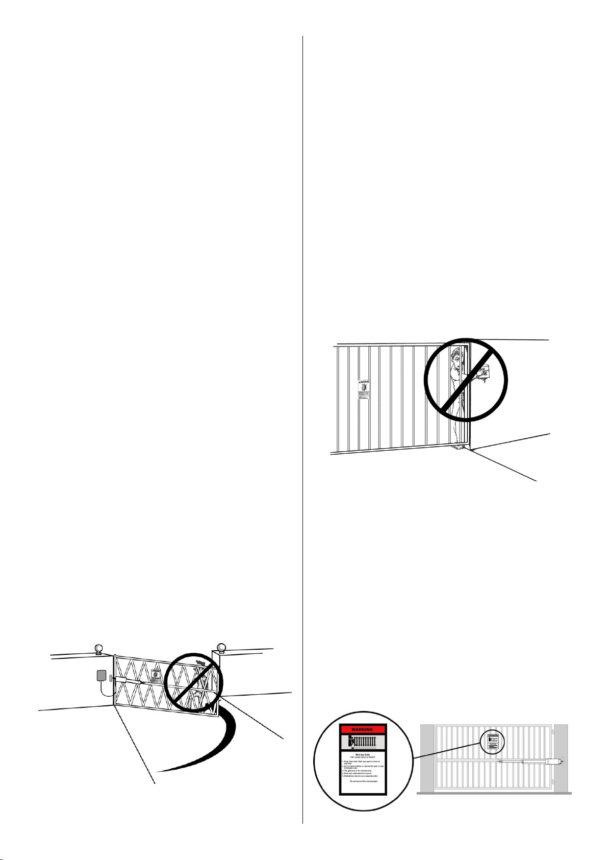
8. Pedestrians should never cross the pathway of a
moving gate. The gate opener is not acceptable for
use on any pedestrian gate. Pedestrians must be
supplied with a separate pedestrian access.
9. For an installation utilizing non-contact sensors
(safety sensors), see product manual on the
placement of non-contact sensors (safety sensors) for
each type of application.
a. Care shall be exercised to reduce the risk of
nuisance tripping, such as when a vehicle trips the
safety sensor while the gate is still moving.
b. One or more non-contact sensors (safety sensors)
shall be located where the risk of entrapment of
obstruction exists, such as the perimeter reachable by
a moving gate or barrier.
10. Never mount any device that operates the gate
opener where the user can reach over, under, around
or through the gate to operate the controls. Controls
are to be placed at least 6’ (1.8m) from any part of the
moving gate.
11. Controls intended to be used to reset an operator
after 2 sequential activations of the entrapment
protection device or devices must be located in the
line of sight of the gate, or easily accessible controls
shall have a security feature to prevent unauthorized
use. Never allow anyone to hang on or ride the gate
during the entire travel of the gate.
12. Each gate opener is provided with two safety
warning placards. The placards are to be installed on
the front and back of the gate where they are plainly
visible. The placards may be mounted using cable ties
through the four holes provided on each placard.
All warning signs and placards must be installed
where visible in the area of the gate.

2
13. To AVOID damaging gas, power, or other
underground utility lines, contact underground
utility locating companies BEFORE digging.
14. Do not permit children to play on or around the
gate and keep all controls out of their reach.
NOTE:
TOPENS Gate Operator can be used for driveway gates made by steel, wood, vinyl, and shaped as panel,
tube, and chain-link. While use on solid surface gates is NOT recommended. Solid surface gates have a high
resistance to the wind. If the wind is strong enough, the operator will obstruct and stop.

3
A3131 Parts List

4
A5131 / A8131 Parts List

5
Extra Parts for A3131/ 5131/ 8131 S
Accessories Parts (Included in some models, refers to the actual package)
Optional Accessories Parts List (Available at TOPENS Store)
M12 Remote Control
ERM12 External
Receiver
TC186-R WiFi
Smartphone Remote
Control with Camera
TC188 Universal
Wireless and Wired
Keypad
TKP3 Wireless Keypad
TC175P Wired Keypad
TEW3 Vehicle Sensor
Exit Wand
HLR01 HomeLink
Remote Control Kit
TC173 Wireless Push
Button
TC147 Wall Push
Button
TC148 Waterproof Wall
Push Button
TRF3 Reflection
Photocell Sensor
TC102 Photo Eye Beam
Sensor
JD24VY 24V Warning
Light
TSP30W 30W Solar
Panel Charging Kit
TSQ20W 20W
Solar Panel Kit

6
25FT Extension
5 Conductor Cable
ET24 Electric Gate
Lock
Replacement Parts
EKPKMJ2B Control
Board for A3131/
A3131S Gate Opener
EKPKMJ1B Control
Board for A5131/
A5131S/ A8131/
A8131S Gate Opener
ALS01 Limit Switch
A3JB/ A5JB/ A8JB Arm
Actuator
UPS01 Uninterrupted
Power Supply
MK01 Hardware Kit
Tools Needed:
·Power Drill
·Tape Measure
·Open End Wrenches - 14# &17# or Adjustable Wrenches
·Wire Strippers
·C-Clamps - small, medium, and large
·Level
·Hacksaw or Heavy Duty Bolt Cutters
·Phillips Screwdriver
Technical Specifications & Features
Specifications
A3131(S)
A5131(S)
A8131(S)
Input:
UPS01 AC Input: 110-240V~ 50/60Hz
Motor voltage:
24VDC
Power:
30W
50W
80W
Current:
1.5A
2A
3A
WARNING: Changes or modifications not expressly specified by this user manual, TOPENS could void
the warranty of this equipment.
7
Actuator speed:
16mm/s(0.6 in/s)
Max. actuator travel:
385mm(15.2 in)
Ambient Temperature:
-20℃~ +50℃(0°F to 120°F)
Protection class:
IP44
These specifications are subject to change without notice.
Features:
·Soft start and soft stop
·Emergency release key in case of power failure
·Fast selecting push/pull to open
·Stop in case of obstruction during gate opening.
·Reverse in case of obstruction during gate closing.
·Built in adjustable auto-close (3-120 seconds)
·Built in max. Motor running time (MRT) for multiple safety protection (40 seconds)
·Reliable electromagnetism limit for easy adjustment
·Can be equipped with a wide range of accessories
·Easy to install, and minimum maintenance requirement
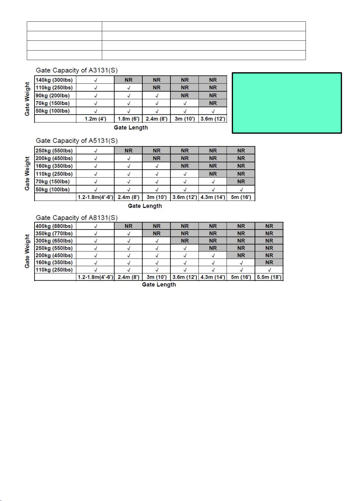
NOTE: “NR" indicates this size and
weight combination is NOT
recommended for one arm actuator.
NOTE: Ball bearing hinges should
be used on all gates weighing over
140kg (300 lbs).

8
Installation Overview
Preparation for Installation
There are two installation types for the gate opener, Pull-to-Open and Push-to-Open.
In the Push-to-Open installation, gate opens out from the property. A Push-To-Open Bracket (PSO part) is
required to be used for each gate.
The gate opener is mounted to the gate and to the gate post. Both round and square posts can be used
because the Post Brackets are curved. When mounting the Post Brackets, use bolts long enough to pass
through the entire post. M10 x 200 bolts are included. Concrete anchors are not provided.
When mounting the Post Brackets to wooden posts, a larger-size washer or metal plate should be used
between the bolts and the wooden post to ensure the stability of the fastening hardware. If the post is smaller
than 6" diameter or square, it should be made of metal and set in cement to ensure its stability.
NOTE: Ensure the gate does not open into public areas. One more person will help when installing.

9
Install the Opener on the Gate – for Pull to Open
The position of Post Bracket is very important. The following illustrations and tables are required to determine
the proper mounting position for the Post Bracket. The tables show the maximum opening angle of the gate for
a given A and B. For example, if A is 16cm and B is 14cm, the maximum opening angle of the gate is 110°
Pull-to-Open Installation — Gate in Closed position (Moving-Rod is extended)
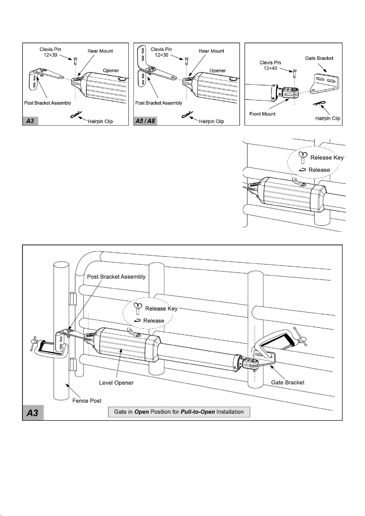
1. Insert the bolts through the holes of post bracket and post pivot bracket as shown. Place washers and nuts
on the bottom of the bolts and hand tighten.
10
2. Attach the gate bracket and post bracket assy. to the opener by inserting a clevis pin. Secure the clevis pins
using the hairpin clips.
3. Open the release hole plug on the top of the gate opener, insert the
release key, and turn the key 90° clockwise. This releases the motor and
allows the push-pull rod to be manually extended and retracted. To restore
normal operation, turn the key 90° counterclockwise.
4. With the opener fully retracted and with the gate in the fully open
position (for Pull-to-Open installation), place the opener with the Post
Bracket Assy. and Gate Bracket on the gate post and the gate. While
holding the gate opener in the level position, temporarily secure it with two
C-clamps.

11
5. Make sure that there is a minimum clearance of 2.5cm between the gate and the opener and that the opener
and the Post Pivot Bracket are not binding in both the gate-open and gate-closed positions. If there is not at
least 2.5cm of clearance or if the opener and the Post Pivot Bracket are binding, rotate the Post Pivot Bracket
and/or move the Post Bracket Assy. to obtain the minimum clearance and eliminate the binding.
6. Sign the bolt-hole point on the gate post and gate. Do this by placing a punch or a sign in the middle of each
bolt slot on the post bracket and the gate bracket. It allows slight adjustments to the post bracket. Then remove

12
the opener and brackets assy. by taking off
the C-clamps.
7. Drill 10.5 mm diameter holes through the
post and the gate at the marked locations.
8. Attach the post bracket assemblies to
the gate post by inserting M10 x 200 bolts
through each post bracket assy. and the
drilled holes in the gate post. Fasten each
bolt with one ¢10 washer, one ¢10 lock
washer, and one ¢10 nut.
9. Attach the gate brackets to each gate by
inserting two M10 x 75 bolts through the
gate brackets and the drilled holes in the gates. Fasten each bolt with one ¢10 lock washer, and one ¢10 nut.
10. Cut off any part of the bolts that extend beyond the tightened nuts.
11. With the opener fully retracted and with the gate in the fully open position (for Pull-to-Open installation),
insert a clevis pin through the gate opener and the Post Pivot Bracket and insert another clevis pin through the
gate opener and the Gate Bracket. Secure each clevis pin with a hairpin clip.

13
12. Open the release hole plug on the top of the gate opener, insert the release key, and turn the key 90°
counterclockwise. This restores normal operation.
NOTE: The setting of the PULL/PUSH TO OPEN of the control board should be in accordance with the
installation.
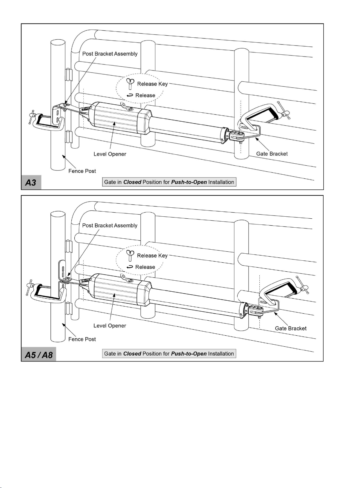
Install the Opener on the Gate – for Push to Open
The position of Post Bracket is very important. The following illustrations and tables are required to determine
the proper mounting position for the Post Bracket. The tables show the maximum opening angle of the gate for
a given A and B. For example, if A is 15cm and B is 12cm, the maximum opening angle of the gate is 110°
Push-to-Open Installation — Gate in Closed position (Moving-Rod is retracted)

14
1. Insert the bolts through the holes of post bracket and PSO part (push to open bracket) as shown. Place
washers and nuts on the bottom of the bolts and hand tighten.
2. Attach the gate bracket and post bracket assy. to the opener by inserting a clevis pin. Secure the clevis pins
using the hairpin clips.
3. Open the release hole plug on the top of the gate opener, insert the
release key, and turn the key 90° clockwise. This releases the motor and
allows the push-pull rod to be manually extended and retracted. To restore
normal operation, turn the key 90° counterclockwise.
4. With the opener fully retracted and with the gate in the fully closed
position (for Push-to-Open installation), place the opener with the Post
Bracket Assy. and Gate Bracket on the gate post and the gate. While
holding the gate opener in the level position, temporarily secure it with two
C-clamps.
15
5. Make sure that there is a minimum clearance of 2.5cm between the gate and the opener and that the opener
and the PSO part are not binding in both the gate-open and gate-closed positions. If there is not at least 2.5cm
of clearance or if the opener and the PSO part are binding, rotate the PSO part and/or move the Post Bracket
Assy. to obtain the minimum clearance and eliminate the binding.

16
6. Sign the bolt-hole point on the gate
post and gate. Do this by placing a punch
or a sign in the middle of each bolt slot
on the post bracket and the gate bracket.
It allows slight adjustments to the post
bracket. Then remove the opener and
brackets assy. by taking off the
C-clamps.
7. Drill 10.5 mm diameter holes through
the post and the gate at the marked
locations.
8. Attach the post bracket assemblies to the gate posts by inserting M10 x 200 bolts through each post bracket
assy. and the drilled holes in the gate post. Fasten each bolt with one ¢10 washer, one ¢10 lock washer, and
one ¢10 nut.
9. Attach the gate brackets to each gate by inserting two M10 x 75 bolts through the gate brackets and the
drilled holes in the gates. Fasten each bolt with one ¢10 lock washer, and one ¢10 nut.

17
10. Cut off any part of the bolts that extend beyond the tightened nuts.
11. With the opener fully retracted and with the gate in the fully close position (for Push-to-Open installation),
insert a clevis pin through the gate opener and the PSO part and insert another clevis pin through the gate
opener and the Gate Bracket. Secure each clevis pin with a hairpin clip.
This manual suits for next models
5
Table of contents
Other Topens Gate Opener manuals

Topens
Topens HLR01 User manual

Topens
Topens RK990 User manual

Topens
Topens CK500 User manual

Topens
Topens KD702 User manual

Topens
Topens Casar MT8012 User manual

Topens
Topens A3132 User manual

Topens
Topens AT6132 User manual

Topens
Topens AT602 User manual

Topens
Topens CK1100 User manual

Topens
Topens DK1000 User manual

Topens
Topens DKC500 User manual

Topens
Topens BK800 User manual

Topens
Topens DKR500 User manual

Topens
Topens MK1101 User manual

Topens
Topens TEW3 User manual

Topens
Topens LC1100 User manual

Topens
Topens AT6131 User manual

Topens
Topens DKC2000 User manual

Topens
Topens CK2500 User manual

Topens
Topens CK2600 User manual


