manuals.online logo
Brands
  1. Home
  2. •
  3. Brands
  4. •
  5. DoorKing
  6. •
  7. Gate Opener
  8. •
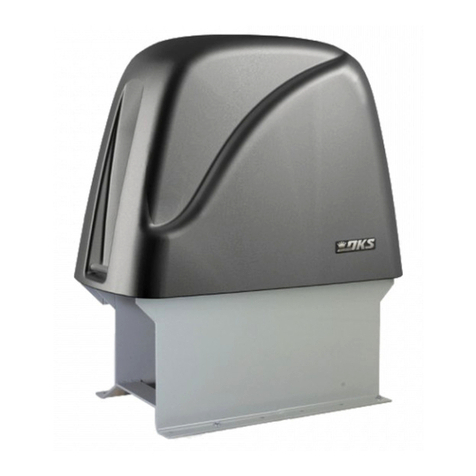
  9. DoorKing 9000 Series User manual

DoorKing 9000 Series User manual

Partial Open
PUSH TO OPERATE
technician use only
Lock Plate
Power
Manual Release
Reset
1
Motor
2
Motor
3
Neutral
4
24VAC
5
Limit
6
Spare
7
Limit
8
COM
3
2
1
6
5
4
9
8
7
#
0
*
Radio Receiver
1
ON
2 3 4 5 6 7 8 1
ON
2 3 4
QUICKSTART “BASIC” GUIDELINES FOR MODEL 9000 - FRONT INSTALLATION MOUNTED ON A CONCRETE PAD “FULL OPEN”
120 Glasgow Avenue
Inglewood, California 90301
U.S.A.
Copyright 2013 DoorKing, Inc. All rights reserved. 9000-066-F-1-13
Use 3/4-inch conduit
with sweeps.
3-Wire
Below ground depth of the concrete pad is
determined by soil conditions and local building
codes (reinforced concrete recommended).
Switch 1
in ON
position.
Use (4) 3/8” x 2” Sleeve Anchors
(Not supplied).
Loop
Conduit
AC Power
Conduit
Concrete
Pad
Opening
Direction
Concrete pad
MUST be level!
Chain Bracket
Chain, Conduit Area and Concrete
4” minimum
above ground.
3.5”
4.5”
13.5”
24”
24”
Conduit Area
Operator Chassis
Idler
Wheel
Center
Position
Bottom
Position
Idler Wheel
Top Position
Center
of
concrete
pad
Concrete Pad
SW 1
12345678
ON
Opening
Direction
Switch 1
in OFF
position.
SW 1
12 3 4 5 6 7 8
ON
Loop Detectors
Radio Receiver
B
B
B
A
E
D
C
Not included - Refer to the Installation/Owner’s manual
for more information about DoorKing’s Plug-In loop
detectors. DoorKing highly recommends that loops and
loop detectors are installed with this slide gate operator.
DoorKing offers a free “Loop and Loop-Detectors
Information Manual” PDF located at DoorKing’s web
site for more information. www.dkaccess.com
CNot included - Refer to a specific Radio Receiver
Manual (available from www.dkaccess.com) for more
information on radio receivers and antenna installation.
(See reverse side for wiring)
High Voltage Connection
Tip: It is recommended that a surge suppressor be
installed on the input high voltage power line.
GATE OPERATOR MUST BE PROPERLY GROUNDED!!
Adjust the 2 limit nuts by depressing the lock plate and spin nuts to
desired open and closed gate positions. After adjusting, make sure
the lock-plate is engaged in the slots on the limit-nuts to prevent
them from rotating.
Note: Partial Open Feature is optional and not used for a fully
opening gate, see manual for more information.
Adjust the chain nuts to tighten the chain. The chain
should sag no more than one (1) inch per 10 feet of
chain travel. Do not over tighten the chain.
Adjustment of Limit Switches
Chain Adjustment
Model 9000 is intended for
installation only on sliding
gates used for vehicles.
Pedestrians must be supplied with
a separate access opening.
For complete safety, installation
and adjustment of operator
instructions, please refer to the
Series 9000 Installation/Owner’s
manual.
A
E
D
Neutral
Hot
115 VAC
Chassis
Ground
Input Power Line:
White - Neutral
Black - 115 VAC Hot
Green - Chassis Ground
DANGER
HIGH VOLTAGE
DIP-Switches
SW 1
1. Opening Direction (See Illustration)
2. OFF
3. ON
4. ON
5. OFF
6. OFF
7. OFF
8. OFF
1. OFF
2. OFF
3. ON
4. OFF
Auto-Close Timer
Adjust
1 to 23 sec.
SW 2
4” minimum
space
between the
gate and
operator
chassis.
Gate
4”
TIME
DELAY
Chain brackets MUST be
mounted so the chain
remains the same height
as it is on the idler wheels!
Operator and chain
MUST be parallel to gate!
Chain bracket MUST line
up with chain idler wheels!
Two 115 VAC
Convenience Outlets
For access control and safety device AC power.
123
Typical Single Operator Settings
DO NOT power up and cycle the
operator until the “DIP-Switches”
and the “Limit Switches” have
been adjusted. Damage could
occur to the gate and operator.
Note: “Optional” High
Voltage Kit black and
white wires connect
the same as shown.
See High Voltage Kit
instruction sheet for
more information.
(See reverse side for
more information).
SW 1 DIP-Switches
SW 2 DIP-Switches
20
19
18
17
16
15
14
13
12
11
10
9
8
7
6
5
4
3
2
1
NC NO
1
2
3
4
5
6
7
8
9
13
12
11
10
14
15
16
17
18
19
20
4
1
2
3
Com
Com
Com
4405-010
Switch 3 Must be ON.
Power (24-Volt DC) and
logic output. Power is shut
off .5 sec. prior to gate
starting and remains off
while gate is opening and
in the open position.
#4 Com
White
24 Volt
1 amp max.
Stand-Alone
Key Switch
Safety
Opening
Device
Stand-Alone
Keypad
Stand-Alone
Card Reader
Telephone
Entry
“Closing-Direction” Photo Sensors
4-Pin Non-Removable Terminal
Note: All stand-alone
and telephone entry devices must
use a separate power source.
Note: When
using 3-button
control station
AND interlock
switch together,
#3 terminal
(N.C.) must be
wired in series.
Remote Alarm Reset Station
(DKS P/N 1404-080) MUST be mounted
in the line-of-sight of the gate operator.
3-Button Control Station
Use a standard 4-wire 3-button
control station. DoorKing’s
3-wire 3-button control station
cannot be used.
Normally Closed
Interlock Switch
SW 1, switch 5: After photo
sensor beam gets obstructed:
OFF- Reverses gate.
Partial
Open
Full
Open
Full
Open
#3 Stop N.C.
#2 Close N.O.
#1 Open N.O.
To #4 Com
To #3 Stop N.C.
N.O.
N.C. Com
Operator Cycling
Lock Engaged
N.O.
N.C. Com
Operator Stopped
Lock Disengaged
Red
Blue
Alarm
Alarm
Reset
#5 Terminal Note: Any opening device connected to terminal #5 will open the gate to
the partial open setting. Secondary entrapment protection devices will also open the
gate to the partial open setting. If the inherent reverse sensor gets activated during the
close cycle, it will always fully open the gate.
OPEN
STOP
CLOSE
SW 1
1
ON
2 3 4 56 7 8
SW 1
1
ON
234 5 6 7 8
PUSHTO OPERATE
technicianuseonly
Power
Power is limited
to 250 mamps.
3-Wire Radio
Receiver
Com
24 Volt
Relay
1
Motor
2
Motor
3
Neutral
4
24VAC
5
Limit
6
Spare
7
Limit
8
COM
3-Pin
Remote
Terminal
123
Place jumper
on bottom
2 pins when
using 4-pin
terminal.
3-Pin With
Jumper
Magnetic Lock
#4 Normally Open
#2 Normally Open
#6 Normally Open
#9 Normally Close
ON - Stops gate then continues closing when gate
is clear (Same function as UL 325 terminal #2).
Note: The ON setting is used to help prevent
tailgating but the photo sensor should be wired to the UL 325
terminal #2 when the “stop gate” function is desired, see
Installation/Owner’s manual for more information.
Important: Controls must be far enough from the gate so that the user is prevented from
coming in contact with the gate while operating the controls. Outdoor or easily accessible
controls should have a security feature to prevent unauthorized use.
Model 9000 is intended for installation only on slide gates used for vehicles.
Pedestrians must be supplied with a separate access opening.
For safety and installation instructions, please refer to the Installation/Owner’s manual.
QUICKSTART “BASIC” GUIDELINES FOR MODEL 9000 - DIP-SWITCH AND WIRING REFERENCE
120 Glasgow Avenue
Inglewood, California 90301
U.S.A.
Switch Function Setting Description
Primary
Operator
Opening
Direction
OFF
ON
OFF
ON
OFF
ON
OFF
ON
7-OFF
7-OFF
7-ON
7-ON
8-OFF
8-ON
8-OFF
8-ON
Auto-Close
Timer
Single Operator
Dual Operators
Relay
1
2
3
4
5
6
7 and 8
The output wired to terminal #4 becomes the output from the exit loop detector
plugged into the EXIT Loop port.
Normal Setting. Terminal #4 is a normal full open input.
Auto-close timer is OFF. Manual input required to close gate.
Normal Setting. Auto-close timer is ON. Adjustable from 1-23 seconds.
Normal Setting. Switch must be OFF for single operator.
Switch must be ON when primary/secondary (dual) gates are used.
Normal Setting. Relay activates when gate is at open limit.
Relay activates when gate is not closed.
Relay activates when gate is opening and open.
Relay activates during opening and closing cycle.
Switch Function Setting Description
Normal Setting. Switch 3 MUST be turned ON for Model 9000 operator.
Normal Setting. Switch 4 MUST be turned OFF for Model 9000 operator.
OFF
ON
OFF
ON
ON
OFF
Magnetic lock
1
2
3
4
Normal Setting. Magnetic lock is not used.
Magnetic lock is used and connected to terminals 9 and 12.
Opening direction
using ON setting.
Opening direction
using OFF setting. Changes direction operator will cycle open
upon initial AC power up and open command.
Changes direction operator will cycle open
upon initial AC power up and open command.
Opening direction
using ON setting.
Opening direction
using OFF setting.
Secondary
Operator
Opening
Direction
Reverses Gate
Stops Gate
Quick-Close
Timer Override
Exit Loop Port
Output
Full Open Input
Normal Setting. Input to terminal #6 and reverse loop will reverse gate during
close cycle.
Input to terminal #6 and/or reverse loop will stop gate during close cycle – gate will
continue to close after input to terminal #6 and/or reverse loop are cleared (Helps
prevent tailgating).
Note: After a DIP-switch setting is changed, power must be turned
OFF and then turned back on for the new setting to take affect.
Normal Setting. Timer will function normally.
Opening gate will stop and begin to close as soon as all reversing inputs (Reverse
loops, photo sensors) are cleared regardless of the distance the gate has opened.
SW 1
SW 2
1
ON
2 3 4 5 6 7 8 1
ON
2 3 4
Other manuals for 9000 Series

2

Other DoorKing Gate Opener manuals

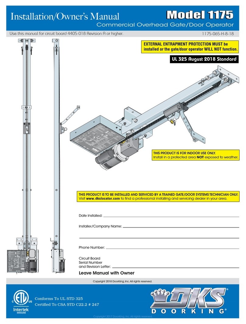
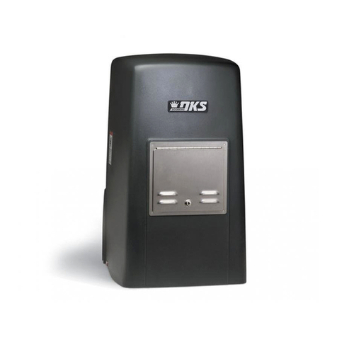
DoorKing 6003 User manual

DoorKing

DoorKing 6003 User manual

DoorKing 9000 Series Operating instructions

DoorKing

DoorKing 9000 Series Operating instructions

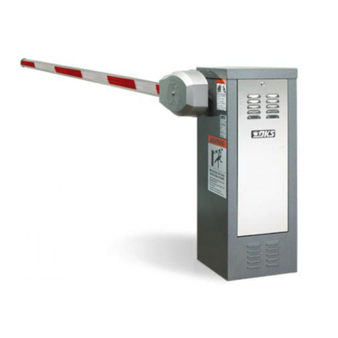
DoorKing 6500 Series Operating instructions

DoorKing

DoorKing 6500 Series Operating instructions

DoorKing 1175 Installation guide

DoorKing

DoorKing 1175 Installation guide

DoorKing 9000-080 Operating instructions

DoorKing

DoorKing 9000-080 Operating instructions

DoorKing 9245 User manual

DoorKing

DoorKing 9245 User manual

DoorKing 6004 User manual

DoorKing

DoorKing 6004 User manual

DoorKing Series 9500 Installation instructions

DoorKing

DoorKing Series 9500 Installation instructions

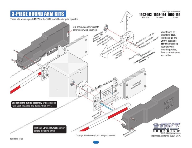
DoorKing 1602-162 User manual

DoorKing

DoorKing 1602-162 User manual

DoorKing Series 9500 User manual

DoorKing

DoorKing Series 9500 User manual

DoorKing 6555 Operating instructions

DoorKing

DoorKing 6555 Operating instructions

DoorKing 9100 User manual

DoorKing

DoorKing 9100 User manual

DoorKing 9150 Series User manual

DoorKing

DoorKing 9150 Series User manual

DoorKing 4302 User manual

DoorKing

DoorKing 4302 User manual

DoorKing 1601-295 User manual

DoorKing

DoorKing 1601-295 User manual

DoorKing 9150 Series Operating instructions

DoorKing

DoorKing 9150 Series Operating instructions

DoorKing 6006 User manual

DoorKing

DoorKing 6006 User manual

DoorKing 1603 Operating instructions

DoorKing

DoorKing 1603 Operating instructions

DoorKing 1601 Series User manual

DoorKing

DoorKing 1601 Series User manual

DoorKing 6004 User manual

DoorKing

DoorKing 6004 User manual

DoorKing 1175 Operating instructions

DoorKing

DoorKing 1175 Operating instructions

DoorKing Series 9500 Operating instructions

DoorKing

DoorKing Series 9500 Operating instructions

DoorKing 9150 Series Operating instructions

DoorKing

DoorKing 9150 Series Operating instructions

DoorKing 6400 User manual

DoorKing

DoorKing 6400 User manual

Popular Gate Opener manuals by other brands

DIMOEL Kit ElectroDue manual

DIMOEL

DIMOEL Kit ElectroDue manual

LockMaster DKL400UY user manual

LockMaster

LockMaster DKL400UY user manual

FAAC 746 ER CAT installation manual

FAAC

FAAC 746 ER CAT installation manual

Nice Toona TO4006 Instructions for installation and use

Nice

Nice Toona TO4006 Instructions for installation and use

EasyGate TERRIER Series user manual

EasyGate

EasyGate TERRIER Series user manual

SOMFY Dexxo Optimo RTS installation manual

SOMFY

SOMFY Dexxo Optimo RTS installation manual

Cardin Elettronica 200/BL3924ERB instruction manual

Cardin Elettronica

Cardin Elettronica 200/BL3924ERB instruction manual

Mighty Mule MM272 installation manual

Mighty Mule

Mighty Mule MM272 installation manual

CAME FROG series manual

CAME

CAME FROG series manual

Motorline professional PERSA 400 User's and installer's manual

Motorline professional

Motorline professional PERSA 400 User's and installer's manual

SOMFY SGA 6000 manual

SOMFY

SOMFY SGA 6000 manual

Nortek Security & Control Mighty Mule TS571W installation manual

Nortek Security & Control

Nortek Security & Control Mighty Mule TS571W installation manual

Casit TORINO 06 Installation and maintenance manual

Casit

Casit TORINO 06 Installation and maintenance manual

Roger Technology BH23 Series quick start guide

Roger Technology

Roger Technology BH23 Series quick start guide

King Pigeon RTU5024 user manual

King Pigeon

King Pigeon RTU5024 user manual

GR ASA6 ID410 Series manual

GR

GR ASA6 ID410 Series manual

Cardin Elettronica 101/SL402409 manual

Cardin Elettronica

Cardin Elettronica 101/SL402409 manual

Allmatic I2500 Series manual

Allmatic

Allmatic I2500 Series manual

manuals.online logo
manuals.online logoBrands
  • About & Mission
  • Contact us
  • Privacy Policy
  • Terms and Conditions

Copyright 2025 Manuals.Online. All Rights Reserved.