AUTOCAPACIBANK™ and AUTOCAPACITRAP™
Installation and Operations Manual
7
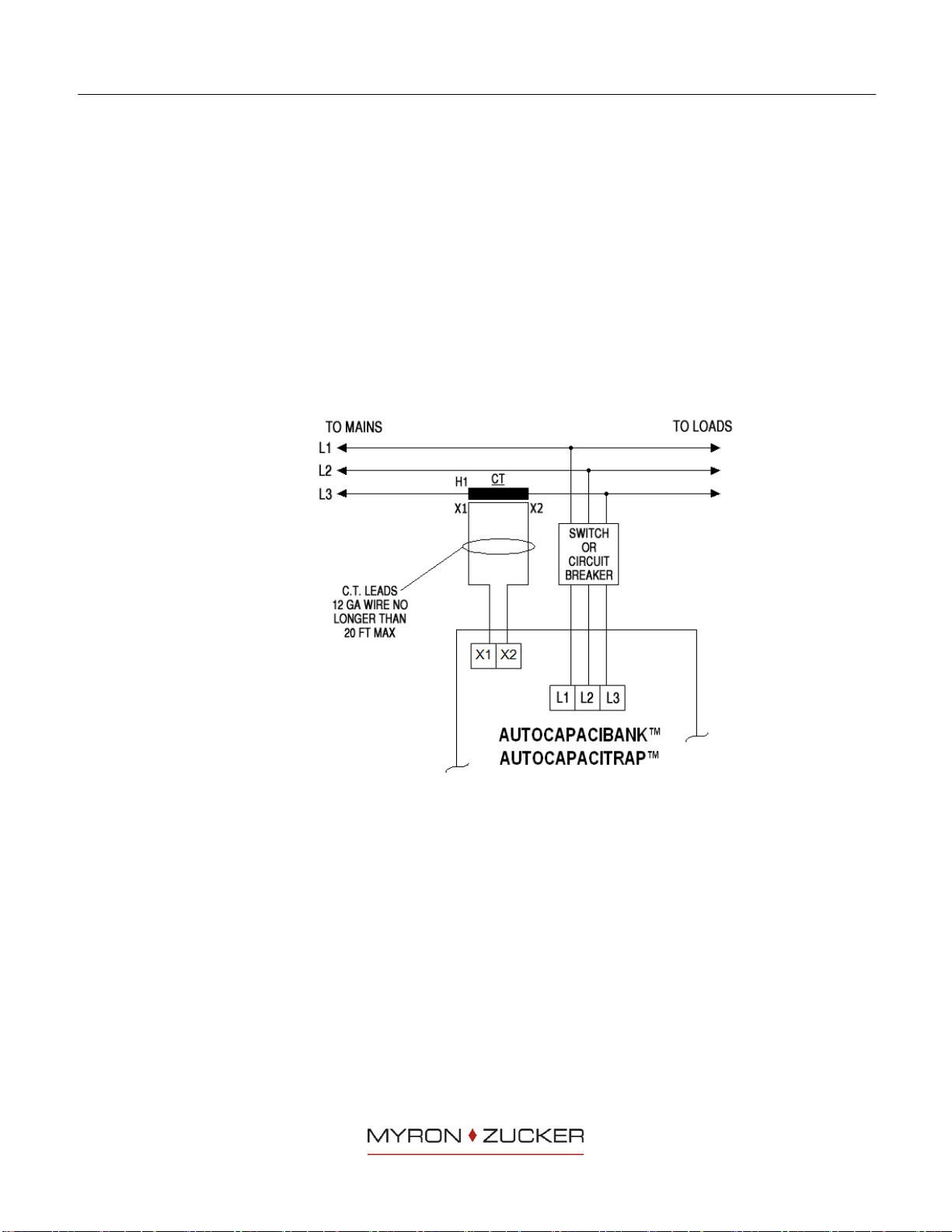
Open the CT shorting terminal and confirm that there is current on the CT
secondary wires using a clamp-on ammeter.
Note: The CT knife switch terminal must be open for the VAR Controller to
operate.
Energize the Autocapacibank™or Autocapacitrap™by closing the main
breaker or disconnect feeding the equipment.
Confirm that there is correct voltage on L1, L2 and L3.
Wait for 60-second lock-out time to elapse. During this time steps will not be
activated.
If the installation is correctly connected, the VAR Controller will now switch
successive steps, following the selected step time delay until the target power
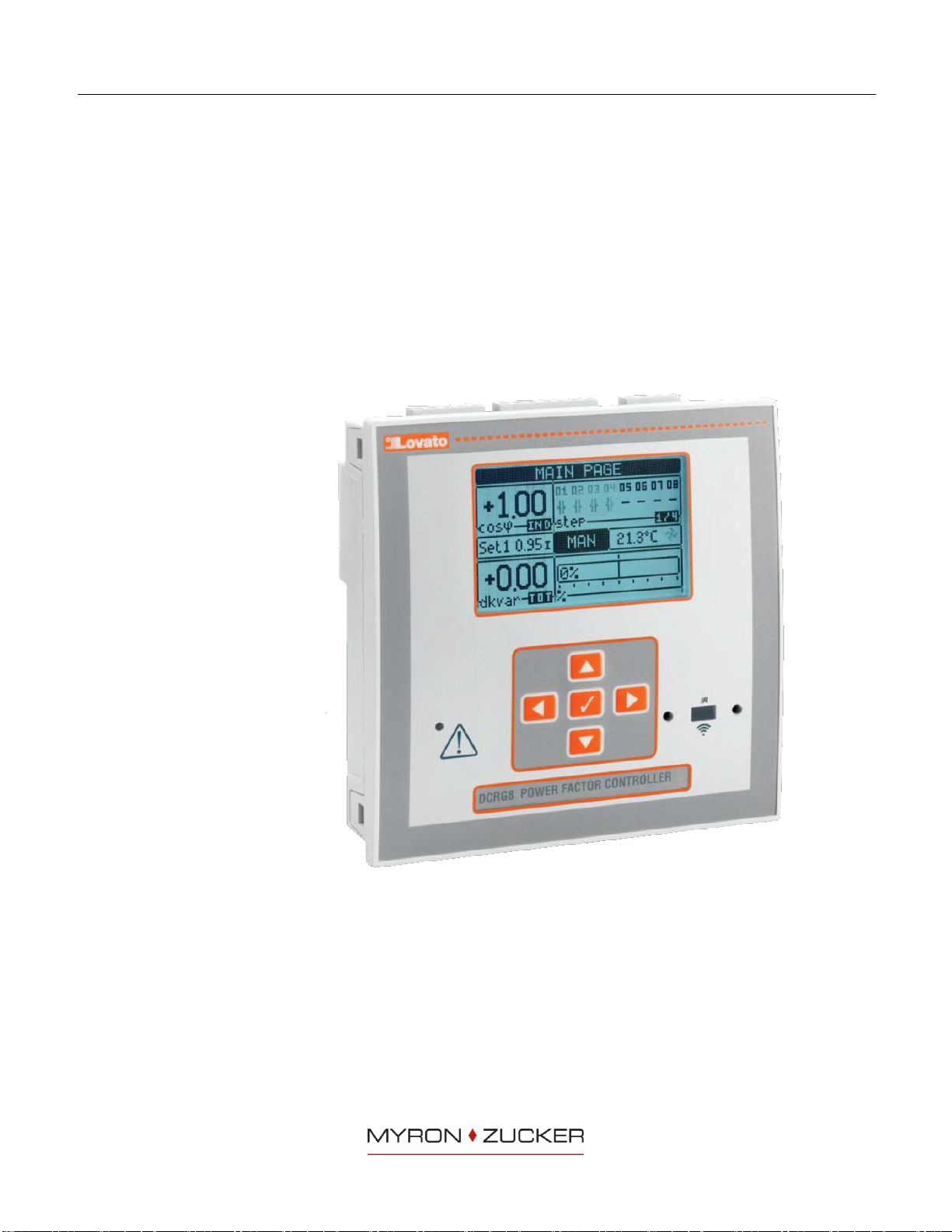
factor is obtained. Each energized step will be indicated on the LCD Display (4
in FIGURE 2). As each step switches in/out the digital display of power factor
will change.
The LOVATO VAR Controller does not require any adjustment of C/K-value
(threshold level when to start to switch in/out steps), since the step sizes will
be sensed automatically. The controller will select a suitable capacitor in order
to achieve the target. With equal sized capacitor steps the controller distributes
the switching operations equally to the capacitors.
A flashing display segment indicates that the relay is searching for a suitable
capacitor size (inductive or capacitive) in order to meet the required target
power factor. If no suitable size is available, then no switching will take place,
and the segment will continue to flash until the power factor is obtained.
Note: Due to delays programmed into the VAR Controller, it may take up to 10
minutes for all the contactors to energize.
At this point, the display will read the load power factor and indicate which
capacitor stages are connected.
If the load power factor is at or above the controller power factor set-point, then
the commissioning is finished.
If the power factor remains low, even though some or all of the stages have
been energized, or if the display shows a capacitive power factor even though
no stages have been energized, then a re-check of correct wiring must be
completed.
4.4 Autocapacibank™ or Autocapacitrap™Shut Down Procedure
Place the VAR Controller in “MAN” mode.
Select energized steps and de-energize each step.
Open main breaker or disconnect only after all steps have been de-energized.
Close the CT shorting terminal.