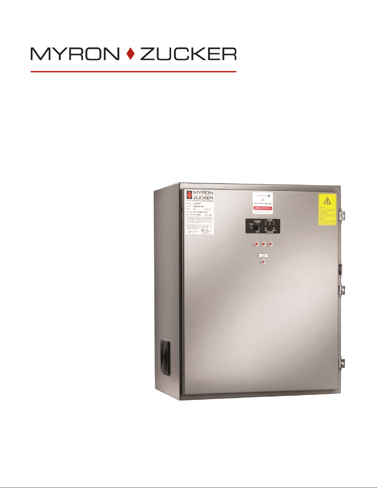
CALTRAP™
Installation and Operations Manual
4
4. PREVENTATIVE MAINTENANCE PROCEDURES
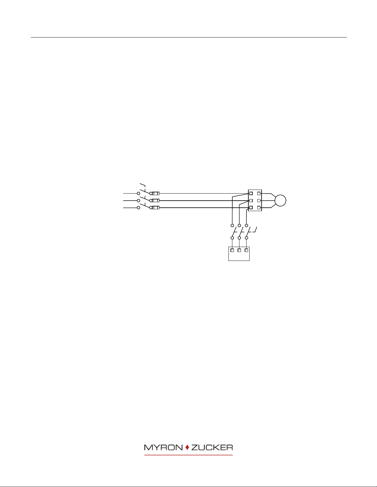
WIRE CONNECTIONS
All power wire connections should be inspected for tightness one (1) month after
commissioning and every six (6) months thereafter.
CAPACITOR CELLS
Capacitor cells should be visually checked for distorted tops one (1) month after
commissioning and every six (6) months thereafter.
INDICATION LIGHTS
Blown fuse indication lights may be checked daily.
CLEANLINESS
Every six (6) months the fan filters should be inspected and cleaned or replaced
and the unit should be clean of all contaminants. Note: DO NOT USE HIGH
PRESSURE LIQUID TO CLEAN UNITS.
CONTACTORS
Remove covers and visually check contacts for signs of wear and excessive arcing
every six (6) months. Energize each contactor with the controller in "manual" mode
to ensure proper operation.
How to Check Fuses:
Trouble: Fuse light is illuminated.
This indicates that a fuse is blown. Typically, power surges or a bad capacitor
causes a fuse to blow.
Disconnect power from the capacitor unit and wait one minute after the
power has been disconnected to allow the capacitors to discharge.
Check affected capacitor following steps below: How to Test a Capacitor Cell.
Replace affected fuse.
How to Test a Capacitor Cell:
With a Capacitance Meter
Capacitor cells are rated in microfarad and voltage. The easiest way to test a cell
is to measure the microfarads with a capacitance meter.
Disconnect power from the capacitor unit and wait one minute after the
power has been disconnected to allow the capacitors to discharge.
Measure microfarads using a capacitance meter. The microfarads should be
equal to the microfarad rating or up to 5% over the rating.
If microfarads are below the minimum, the cell is going bad.
Replace bad capacitor cells.
Visual Inspection of Cell
If a capacitor meter is not readily available, the status of a cell can sometimes be
determined visually.
If the cell can is "bulged out" or "pouched up" on the top, it is definitely bad.
Disconnect power from the capacitor unit and wait one minute after the
power has been disconnected to allow the capacitors to discharge.
Replace bad capacitor cells.