MyTana RT8872 User manual

Manufacturers of Quality
Sewer & Drain Cleaning
Equipment since 1957
1.800.328.8170
Factory Direct Customer Service
M –F 7am – 5pm CST
Competent • Polite • Clear
www.MyTana.com
746 Selby Ave • St. Paul MN, 55104
fax: 651.222.1739
RT8872 Transmitter
Quick Guide
Prepare for Use
When you unpack your RT8872 Transmitter, make sure there is no shipping damage.
The RT8872 comes with “C” batteries already installed. If you need to change the
batteries, the compartment is located on the back of the Transmitter.
RT8872 Transmitter Indicators and Controls
DC Jack
(disabled)
Transmitter Output Jack
The Red/Black Cord, Coupler and
Flexicoupler connect here to create a
direct connect or coupler inductive
circuit on the buried utility.
Load Rate Indicator
Indicator symbol ashes to
indicate signal transmission
via coupler induction
or direct connection.
INDICATORS/DISPLAY
CONTROLS
Relative Resistance,
Voltage and Current
The transmitter can display
the resistance, voltage and
amperage of the trans-
mitted frequency.
NOTE: This is a relative
measurement based on
the feedback from the
transmitted signal.
Output
Signal Level
Adjusts the power
output from the
Transmitter.
Frequency Selector
Selects frequencies
by toggling through
available frequencies.
8kHz, 65Hz, 200 Hz,
480Hz, 33kHz &
82kHz are standard
on the 8869.
Transmitter
Power ON/OFF
LED panel lights up
when unit is on.
052317
Electric shock hazard:
•Toolisdesignedtodetect
electromagneticeldemittedfrom
CameraSondesandburiedmetallic
utilities.Thereareburiedcables,
pipes,andutilitiesthisinstrument
CANNOTdetect.
•LOCATINGisnotanexactscience.
Theonlycertainwaytobesureofthe
existence,location,ordepthofburied
utilitiesistocarefullyexpose(digup)
theutility.
•De-energizeanycircuitsinor
aroundtheworkarea.
•Donotexposetooltorainormoisture.
•Usetoolonlyforintendedpurpose
asdescribedinthismanual.Failureto
observethesewarningscouldresult
insevereinjuryordeath.
Please inspect product
carefully upon receipt.
Included:
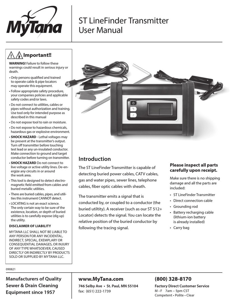
• RT8872 Transmitter
• Grounding Rod
• Transmitter Cable
• Batteries (already installed)
Refer to the RL8873 Quick Guide or
the RL8873-RT8872 Manual for using
this box with the Locator/Receiver
Transmitter Output Jack The Red/Black
Cord, Coupler and Flexicoupler connects
here to create a direct connect or coupler
inductive circuit on the buried utility.
Load Rate Indicator Indicator
symbol ashes to indicate signal
transmission via coupler induction or
direct connection.
INDICATORS
2
2
2
3
1
1
1
3
3
CONTROLS
Relative Resistance,
Voltage and Current
The transmitter can
display the resistance,
voltage and amperage
of the transmitted
frequency.
NOTE: This is a relative
measurement based on
the feedback from the
transmitted signal.
Output
Signal Level
Adjusts the
power output
from the
Transmitter.
Frequency
Selects frequencies
by toggling through
available frequencies.
8kHz, 65Hz, 200 Hz,
480Hz, 33kHz &
82kHz are standard
on the 8872.
Transmitter
Power ON/OFF
Frequency and
other LCD
segments visible
indicates unit is on.
DC Jack
(disabled)

Direct Connection
Direct Connection is the most reliable method of signal application.
This method is relatively free of interference. The greatest amount of signal
strength can be achieved by this method. All frequencies may be used.
The far end of the utility must be grounded.
• Connect the Red Test Cord to an existing ground point or an exposed
metallic section of the utility.
• Place the Ground Rod approximately 10 feet from this point, at an
angle of 90º to the buried cable or pipe.
• Push the Ground Rod into the ground 8 to 10 inches.
• Connect the Black Test Cord to the Ground Rod.
• Plug the Red/Black Test Cord into the Transmitter Output Jack.
• Select Frequency. The Power Output Indicator, Load Rate Indicator and
the Frequency will be displayed.
Flexicoupler Connection
The optional Flexicoupler and Hard Coupler are very easy to use, and
services do not have to be interrupted. The operation range is shorter than
for Direct Connection methods. The tracing signal can be aected by
neighboring cables and pipes. The Red/Black Test Cord or the Ground Rod
are not needed for this method.
uSuccessful coupler operation requires an insulated conductor that is
grounded on both near and far ends.
• Loop the Flexicoupler around the cable and connect the two ends, or
clamp the Hard Coupler around the cable.
It is important to connect the coupler around the cable needing to be
traced. Connect the coupler around the wire closer to the outgoing
cable not near the system ground. The result will be a stronger signal.
By connecting near the grounding, the range will also be shorter, and
diculty may arise determining one cable from another.
• Plug the Coupler Test Cord into the Transmitter Output Jack. Always
select the frequency designated by the coupler. The most common is the
82 kHz FREQUENCY, but coupler are available in multiple frequencies.
Transmitter Specs
Operating Frequency 82 kHz • 33kHz • 8 kHz • 815 Hz
Operating Temperature -4°F to 133º (-20ºC to +55ºC)
Hook-up Method
Direct Connection
Inductive Coupling (with optional coupler)
Transmitter Induction
Load Matching automatic from 5 Ω to 2000 Ω
Output Power 1 Watt (High) 500 Milliwatts (Low)
Battery Types 8 - “C” Duracell alkaline batteries
Battery Life greater than 30 hours*
Dimensions 8.4” x 5.57” x 2.6”
Weight 2.2 lbs (2.8kg)
*depending on load, frequency and power setting
Factory Service
If your RL8872 Transmitter is not working properly,
call MyTana Support at 651-222-1738 for assistance. If the
transmitter is in need of repair, MyTana will provide instructions
and a Return Goods Authorization (RGA) for returning
the Transmitter to the service center.
RMA:
________________
Transmitter
Transmitter
Red cord connects to utility
(unbound this end for
best results)
Inductive coupler
wraps utility
Buried Utility to locate
Black cord
connects
to the
ground
rod
Far end of buried utility
must be bonded
Far end of buried utility
must be bonded
Near end of buried
utility must be bonded
Send it prepaid to:
MYTANA
Attn: Repair (include RGA #)
746 Selby Ave
St. Paul, MN 55104
Note: There is a minimum
charge for repair and handling.
Do not connect to live or
energized power cables
Always turn transmitter OFF before
connecting and disconnecting test leads
!
CAUTION
Other MyTana Transmitter manuals
Popular Transmitter manuals by other brands

Extron electronics
Extron electronics FOX3 T 201 user guide

Greystone Energy Systems
Greystone Energy Systems NDD Series installation manual

Nautel
Nautel NV5LT troubleshooting manual

Inovonics
Inovonics EN1210EOL EchoStream installation instructions

CYP
CYP CH-2603TX Operation manual

Toa
Toa WM-5325 operating instructions