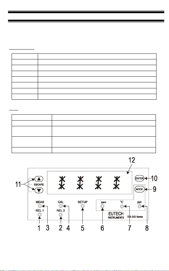
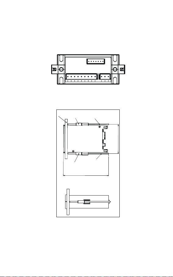
Thermo Scientific Alpha TDS 200 User manual

Alpha TDS 200
1/8DIN Total Dissolved Solids
Controller Transmitter
ppm/ppt/ºC


PREFACE
This manual serves to explain the use of the TDS 200 controller/transmitter.
This manual functions in two ways: first, as a step-by-step guide to help you
operate the meter; second, it serves as a handy reference guide.
This manual is written to cover as many anticipated applications of the TDS
200 controller/transmitter as possible. If there are doubts in the use of the TDS
200 controller/transmitter, do not hesitate to contact the nearest Authorized
Distributor.
Thermo Scientific will not accept any responsibility for damage or malfunction
to the controller/transmitter caused by improper use of the instrument.
The information presented in this manual is subjected to change without notice
as improvements are made, and does not represent a commitment on the part
of Thermo Scientific.
Copyright©Sep 2012 All rights reserved.
Rev. 209/12

TABLE OF CONTENTS
1INTRODUCTION 1
2SAFETY INFORMATION 2
3OVERVIEW 3
3.1 FRONT PANEL 3
3.2 BACK PANEL 4
3.3 WIRING 5
3.4 PANEL-MOUNTING THE CONTROLLER 6
4MEASUREMENT MODE 7
5PASSWORD 8
6TDS CALIBRATION 10
7TEMPERATURE CALIBRATION 12
8SETUP MODE 13
8.1 GENERAL INFORMATION 13
8.2 SETUP MODE OVERVIEW 14
8.3 SET POINT 1 – P1.0 15
8.4 SET POINT 2 – P2.0 17
8.5 MEASUREMENT RANGE SELECTION – P3.0 19
8.6 CONFIGURE TEMPERATURE SETTINGS – P4.0 20
8.7 VIEWING TDS CALIBRATION DATA – P5.0 21
8.8 VIEWING TDS / TEMPERATURE ELECTRODE DATA – P6.0 22
8.9 SET TDS FACTOR – P7.0 23
8.10 CONTROLLER RESET – P8.0 23
9RELAYS 25
10 TRANSMITTER FUNCTION 25
11 SPECIFICATIONS 26
12 ACCESSORIES 27
13 GENERAL INFORMATION 30

1
1INTRODUCTION
Thank you for purchasing a ⅛DIN TDS 200 Controller. This controller is part of a series
of quality process controllers available from Thermo Scientific / Eutech Instruments.
These sturdy, economical TDS controllers are designed with the features and reliability of
a much more expensive instrument.
Your controller includes:
•Removable terminal blocks for easy connections;
•Two mounting brackets for easy panel mounting;
Some features of this controller are:
•Two set point, two SPDT relay operation
•Scrolling, 14-segment LED guides user easily through setup functions
•Reliable power supply from 85 to 260 V AC, 50/60 Hz or DC withstands voltage
fluctuations
•Push-button operation from the front panel
•Single-point calibration for each individual range
•Adjustable hysteresis band prevents rapid contact switching around set-point
•Selectable automatic or manual temperature compensation
•Two-level password protection
•Removable terminal strips for quick and easy connections
•Built-in memory backup retains setup even if power fails, and lets you configure
unit before installation
•Isolated 4-20 mA output for remote monitoring or hard copy recording

2
2SAFETY INFORMATION
This Controller/Transmitter shall be installed and operated only in the manner specified in
the Instruction manual. Only skilled, trained or authorized person should carry out
installation, setup and operation of the instrument.
Before powering up the unit, make sure that power source it is connected to, is as
specified in the top label. Failure to do so may result in a permanent damage to the unit.
The unit has live and exposed parts inside. If it has to be opened, make sure that the
power to the unit is off and disconnected.
The unit is Fuse protected. In the event the fuse has to be replaced, use only those as
specified in the manual.
The degree of protection against electric shock will be achieved only by
observance of the corresponding installation rules.

3
3OVERVIEW
3.1 Front Panel
The front panel consists of a 4-digit LED display, 8 LED annunciators and 4 keys.
Annunciators
1. REL 1 Displayed when Relay 1 is activated
2. REL 2 Displayed when Relay 2 is activated
3. MEAS Displayed in measurement mode
4. CAL Displayed in calibration mode
5. SETUP Displayed in setup mode
6. ppm Displayed when measurement range in parts-per-million
7. oC Unit of the displayed parameter (temperature)
8. ppt Displayed when measurement range in parts-per-thousands
Keys
9. MODE Toggle between TDS and temperature display
10. ENTER Confirm changes or to enter into further levels of sub-menu
11. ▲(increment) Use during calibration and setup modes to increment values.
Press ▲/▼keys together to escape to Measurement mode
11. ▼(decrement) Use during calibration and setup modes to decrease values.
Press ▲/▼keys together to escape to Measurement mode
12. LED Display 14 segment LED display
8.8.8.8.

4
3.2 Back Panel
The back panel consists of three different connectors that can be used with removable
terminal blocks (included):
12 11 10 9 8 7 6 5 4 3 2 1
19 18 17 16 15 14 13
1. VAC live wire
2. VAC neutral wire
3. VAC protective ground wire
4. unused
5. Relay 2 deactivated position (normally closed)
6. Relay 2 center pole
7. Relay 2 activated position (normally open)
8. Relay 1 deactivated position (normally closed)
9. Relay 1 center pole
10. Relay 1 activated position (normally open)
11. 4-20 mA connection, negative
12. 4-20 mA connection, positive
13. Pt 100 connection: sense (jumper to terminal 14 if using 2-wire RTD)
14. Pt 100 connection: input
15. Pt 100 connection: ground
16. TDS positive terminal
17. TDS negative terminal
18. unused
19. unused

5
3.3 Wiring
Caution: Ensure electrical mains are disconnected before proceeding.
1. Connect the power supply to the three-pin terminal block
•VAC live wire = 1
•VAC neutral wire = 2
•VAC protective ground wire = 3
TDS 200 controller accepts voltages from 85 to 260 VAC, 50/60 Hz or DC.
2. Connect the Pt 100 leads to terminals 13 to 15 of the seven-pin terminal block. Either
wire can be connected to either terminal. Terminals 13 and 14 must be shunted
unless using a 3-wire RTD.
NOTE: TDS 200 is factory set for Automatic temperature compensation. MTC can be
selected in Program P4.0.
3. Power on the controller. The display automatically shows the TDS reading, the ppm
and ‘MEAS’ annunciators lights.
NOTE: In the event Pt 100 is not connected or the connection is broken in the ATC
mode, the display flashes in TDS mode and display OR in temperature mode.

6
3.4 Panel-mounting the controller
The supplied mounting hardware allows surface mounting to all panels and protective
enclosures. Mounting cut-out size is 91 x 45 mm.
To attach the mounting to the controller:
1. Align the catch to the side of the controller, and insert threaded rods through catch.
2. Screw the threaded-rod through the catch in a clock-wise direction. Tighten until the
catch holds the controller firmly against the back of the panel or protective housing.
Repeat on the other side.
SIDE VIEW
TOP VIEW
approx.154.20
approx.100
Wallp
a
Catch
Threade
d
Catch
Threadedrod

7
4MEASUREMENT MODE
Press MODE to toggle between:
•TDS measurement mode and
•Temperature measurement mode
Total Dissolved Solids Measurement Mode
The controller displays the selected TDS range number, R X (X ranges from 1 to 8), for 2
seconds before displaying the TDS measurement.
TDS Range Range No., R Resolution Cell Constant
0.00 – 10.00 ppm 1 0.01 ppm 0.1
0.0 – 100.0 ppm 2 0.1 ppm 0.1
0.0 – 100.0 ppm 3 0.1 ppm 1
0 – 1000 ppm 4 1 ppm 1
0.00 – 5.00 ppt 5 0.01 ppt 1
0.00 – 10.00 ppt 6 0.01 ppt 1
0.0 – 100.0 ppt 7 0.1 ppt 1
0.0 – 100.0 ppt 8 0.1 ppt 10
Temperature Measurement mode
Press MODE key once to view the temperature measurement. The display shows ATC
(Automatic Temperature Compensation) or MTC (Manual Temperature Compensation),
then the current measured temperature (for ATC) or the set temperature (for MTC). The
oC annunciator lights when you are measuring temperature.
NOTE: After pressing the MODE key to display Temperature, if there is no further key-
press, the Controller will automatically revert to TDS Measurement mode after about 30
seconds.
See Setup program P4.0 for further instructions.

8
5PASSWORD
To access Calibration and Setup functions, you need to enter a password code. You
cannot change calibration and setup parameters unless you first enter the password.
The TDS 200 controller features two separate passwords:
•TDS and Temperature calibration mode password = 011
•Setup program password = 022
To enter the password:
1. Press ENTER twice. The display reads “P.000”. The first “0” flashes.
2. Press ENTER again to leave the first digit “0” and to scroll to the next number.
3. Press the ▲or ▼keys to change the second digit to the correct number (1 or 2).
Press ENTER.
4. Press the ▲or ▼keys to change the second digit to the correct number (1 or 2).
Press ENTER.
If you enter an incorrect digit, press MODE to back up.
5. Press ENTER again. You are now in Calibration mode or Setup mode, depending
on password entered.
Note: In the Password Entry mode, if there is no key-press for more than 30 seconds,
Controller will automatically revert to measurement mode.

9
P
.
P
.
000
P.
000
P
.01 0
P.020
P.0
11
P.022

10
6TDS CALIBRATION
IMPORTANT: When Calibration mode is entered, controller automatically goes into a
“HOLD” mode where the 4-20 mA output freezes and relays are de-activated (if it was in
an activated condition). Upon return to measurement mode, both 4-20mA output and
relay activities resume, depending on settings.
The TDS 200 controller allows one-point slope calibration in one of its eight total
dissolved solids measurement ranges.
Choose fresh standard solutions, whose value is reasonably close to the measurement
value.
Before calibration, make sure electrode is clean. Use iso-propyl alcohol followed by
thorough rinsing in distilled water to clean electrode.
Important: To achieve a successful TDS calibration, two conditions must be satisfied:
1. Difference between measured value of standard solution, and actual value of
standard solution, must be within ± 40 %.
(e.g. if value of standard solution is 500 ppm, then allowable measured
values by controller must be within 700 ppm {+ 40%} and 300 ppm{- 40%});
and
2. the lowest possible value must be at least 10% of full scale
(e.g. if range of 0 to 1000 ppm is selected, min. measured value at
calibration, must be at least 100.0 ppm).
If any or both conditions are not satisfied, controller will display ERR 1 (blinking).
1. Key in the password “011” using the method described in Section 5.
2. Controller flashes the value of the standard solution.
3. Use electrode to agitate standard solution to obtain a homogeneous solution and
to dislodge any bubbles. Allow electrode time to stabilize with solution temperature.
4. Use ▲/ ▼keys to adjust displayed readings to the value of the standard solution.
Press ENTER.
5. If any of the two conditions mentioned above is not satisfied, controller will display
ERR1, blinking.
6. If calibration is successful, Controller displays DONE, blinking. Press ENTER to
revert to TDS measurement mode (Relays and 4-20 mA output resume activities
as per previous settings).

11
NOTE: To clear the ERR1 display and return to calibration mode, press ▲/ ▼keys
together.
509
500
done
ENTER
ENTER
Notes:
You can view the calibrated TDS value from Setup program. See Setup program P5.0.
Controller displays calibrated TDS point for selected range.
If calibration is not done for the selected range, controller displays ‘- - - -‘.
If after thorough cleaning of electrode and ERR1 is displayed after an attempted
calibration, consider changing electrode.

12
7TEMPERATURE CALIBRATION
IMPORTANT: When Calibration mode is entered, controller automatically goes into a
“HOLD” mode where the 4-20 mA output freezes and relays are de-activated (if it was in
an activated condition). Upon return to measurement mode, both 4-20mA output and
relay activities resume, depending on settings.
This controller features selectable Automatic Temperature Compensation (ATC) or
Manual Temperature Compensation (MTC).
ATC: ATC mode requires a Pt 100 temperature element. ATC automatically
compensates for temperature fluctuations. ATC temperature readings can be offset by
±10 oC.
Important: If there is no temperature element wired to controller and ATC is selected on,
screen will flash in TDS mode, and an error message (OR) is displayed in temperature
mode.
MTC: MTC lets you select a specific value at which temperature will be compensated.
You can select a manual temperature value from 0 to 50oC. Factory default is 25.0oC.
See Setup program P4.0 for instructions on ATC or MTC selection.
To offset temperature:
1. Press MODE to select oC mode. Display shows MTC or ATC, then temperature.
2. Key in password “011” as per procedure in Section 5.
3. The screen will flash current oC reading.
4. For ATC: Determine temperature of solution with an
accurate meter (such as the Temp 5). Press ▲or ▼keys
to offset oC value on controller display to match value of
the solution you are measuring.
For MTC: Press ▲or ▼keys to offset oC value on
controller display to match desired value.
5. Press ENTER. The display flashes “DONE” for about 3
seconds and returns to temperature measurement mode
(Relays and 4-2- mA output resume activities as per
previous settings)
2
2
.5
2
5.0
d
o
ne
ENTER

13
8SETUP MODE
8.1 General Information
IMPORTANT: When Setup mode is entered, controller automatically goes into a “HOLD”
mode where the 4-20 mA output freezes and relays are de-activated (if it was in an
activated condition). Upon return to measurement mode, both 4-20mA output and relay
activities resume, depending on settings.
To enter setup mode:
1. Key in password “022” using method described in section 5.
2. Press ▲or ▼keys to display various sub-menus shown here.
3. When a sub-menu item is displayed, press ENTER key to enter that sub-menu.
4. Press ▲and ▼keys together (ESCAPE) to leave Setup mode and return to
Measurement mode (Relays and 4-20 mA output resume previous settings).
P
1
.0
P3. 0
P
4
.
0
P5.0
P6.0
P2.0 P7.0
P6.

14
8.2 Setup mode overview
P1.0: Set Point 1
P1.1: select relay 1 set point value
P1.2: select relay 1 as low or high set point
P1.3: set relay 1 hysteresis value
P2.0: Set Point 2
P2.1: select relay 2 set point value
P2.2: select relay 2 as low or high set point
P2.3: set relay 2 hysteresis value
P3.0: Range
P3.1: select measurement range (with the corresponding cell constant value).
Eight measurement ranges are available.
P4.0: Temperature Data
P4.1: select ATC or MTC
P4.2: select temperature coefficient value
P4.3: select normalization temperature
P5.0: Calibration TDS Buffer points
P5.1: view TDS value at which calibration was performed
P6.0: Electrode Properties
P6.1: view cell correcting factor constant value after calibration
P6.2: view temperature offset value after calibration (only if in ATC mode)
P7.0: TDS Factor
P7.1: select TDS factor for appropriate application
P8.0: Reset
P8.1: select yes/no to reset controller to factory defaults

15
8.3 Set Point 1 – P1.0
Setup program P1.0 allows you to set parameters for relay 1.
P1.1: select relay 1 set point value
P1.2: select relay 1 as low or high set point
P1.3: set relay 1 hysteresis value (dead band)
P1.0 P1.1 P1. 2 P1.3
SP 1SP 1SP 1
200 LOW
HIGH
1
00
HYS
t
Press ▲and ▼keys together (ESCAPE) at anytime, to leave Setup mode and return to
Measurement mode.
P1.1: Select relay set point value
Set the TDS value that will activate Relay 1. If measured value overshoots or
undershoots Set Point value, Relay 1 will be activated and corresponding LED on front
panel will light.
1. Key in password “022” as per procedure in Section 5.
2. Screen will scroll P1.0 and SP1. Press ENTER.
3. Screen will scroll P1.1, SP1, then current set point value.
4. Press ▲or ▼keys and adjust first relay set point. Default value is 10% of full scale
of range selected.
5. Press ENTER to confirm and continue to step three of P1.2, or press ▲and
▼keys together to return to P1.0. Press ▲and ▼keys together again, to return to
the TDS measurement mode.
P1.2: Set relay as high or low set point
Select low set point to activate Relay when measured value undershoots Set point;
select high set point to activate Relay when measured value overshoots Set point.
Using both SP1 and SP2, you can select lo/lo, lo/hi, hi/lo or hi/hi set points.
1. Key in password “022” as per procedure in Section 5.
2. The screen will scroll P1.0 and SP1. Press ENTER twice.
3. The screen will scroll P1.2, SP1, and LOW or HIGH (Default is LOW).
4. Use ▲or ▼keys to toggle between LOW and HIGH.
5. Press ENTER to confirm and continue to step 3 of P1.3, or press ▲and ▼keys
together to return to P1.0. Press ▲and ▼keys together again, to return to TDS
measurement mode.
P1.3: Set Hysteresis value

16
Hysteresis prevents rapid contact switching if measured value is fluctuating near the set
point. Once activated, relay will not de-activate until measured value reaches set point
plus hysteresis value.
Example: Low set point is 200.0 ppm and hysteresis 100.0 ppm, relay will activate when
value is below 200.0 ppm, but will not de-activate till measured TDS value rises above
300.0 ppm.
Default hysteresis value is 5% of full scale. The hysteresis window can be set to any
value within the range 0 to 10% of full scale as shown below:
1. Key in password “022” as per procedure in Section 5.
2. The screen will scroll P1.0 and SP1. Press ENTER three times.
3. The screen will scroll P1.3, HYS1, and current hysteresis value.
4. Press ▲or ▼keys to adjust hysteresis value.
5. Press ENTER to confirm. Press ▲and ▼keys together to return to P1.0. Press
▲and ▼keys together again, to return to TDS measurement mode.
Table of contents
Other Thermo Scientific Transmitter manuals

Thermo Scientific
Thermo Scientific Alpha RES 1000 User manual

Thermo Scientific
Thermo Scientific ALPHA PH 2000D DIFFERENTIAL PH CONTROLLER User manual

Thermo Scientific
Thermo Scientific Alpha DO 1000 User manual

Thermo Scientific
Thermo Scientific Alpha DO 500 User manual

Thermo Scientific
Thermo Scientific Alpha pH 800 User manual

Thermo Scientific
Thermo Scientific ALPHA COND 500 - REV 4 User manual

Thermo Scientific
Thermo Scientific ALPHA DO 500 - REV 4 User manual

Thermo Scientific
Thermo Scientific Alpha pH 1000 User manual

Thermo Scientific
Thermo Scientific ALPHA COND 500 - REV 4 User manual

Thermo Scientific
Thermo Scientific Alpha pH 600 User manual