MYTORQ MY-TR User manual

ELECTRIC
SCREWDIVERS
N-DAS FOR MY-TR
System Operation Manual
Y2F210-5-009
2022/01/26

Page 2 of 46
ELECTRIC
SCREWDIVERS
Table of Contents
①User Guide...................................................................................................................................3
②System Requirements................................................................................................................4
③Hardware......................................................................................................................................5
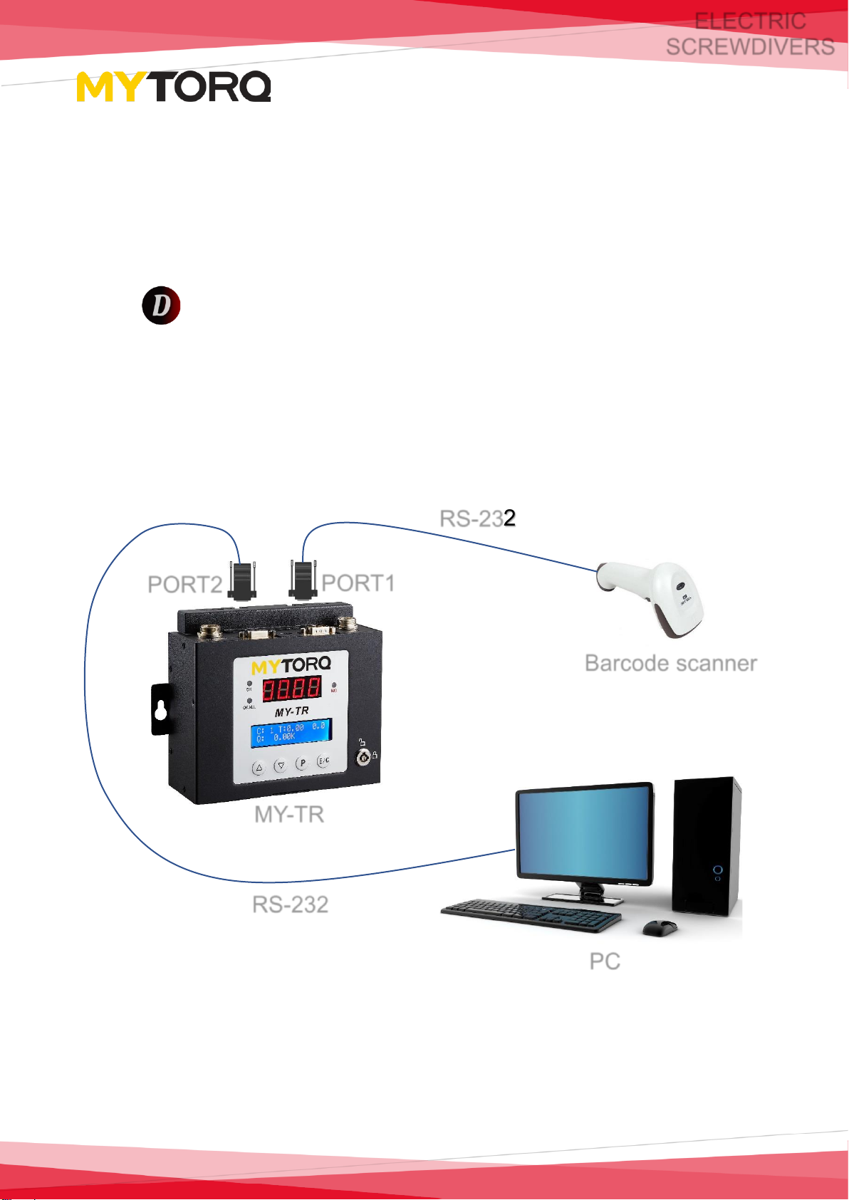
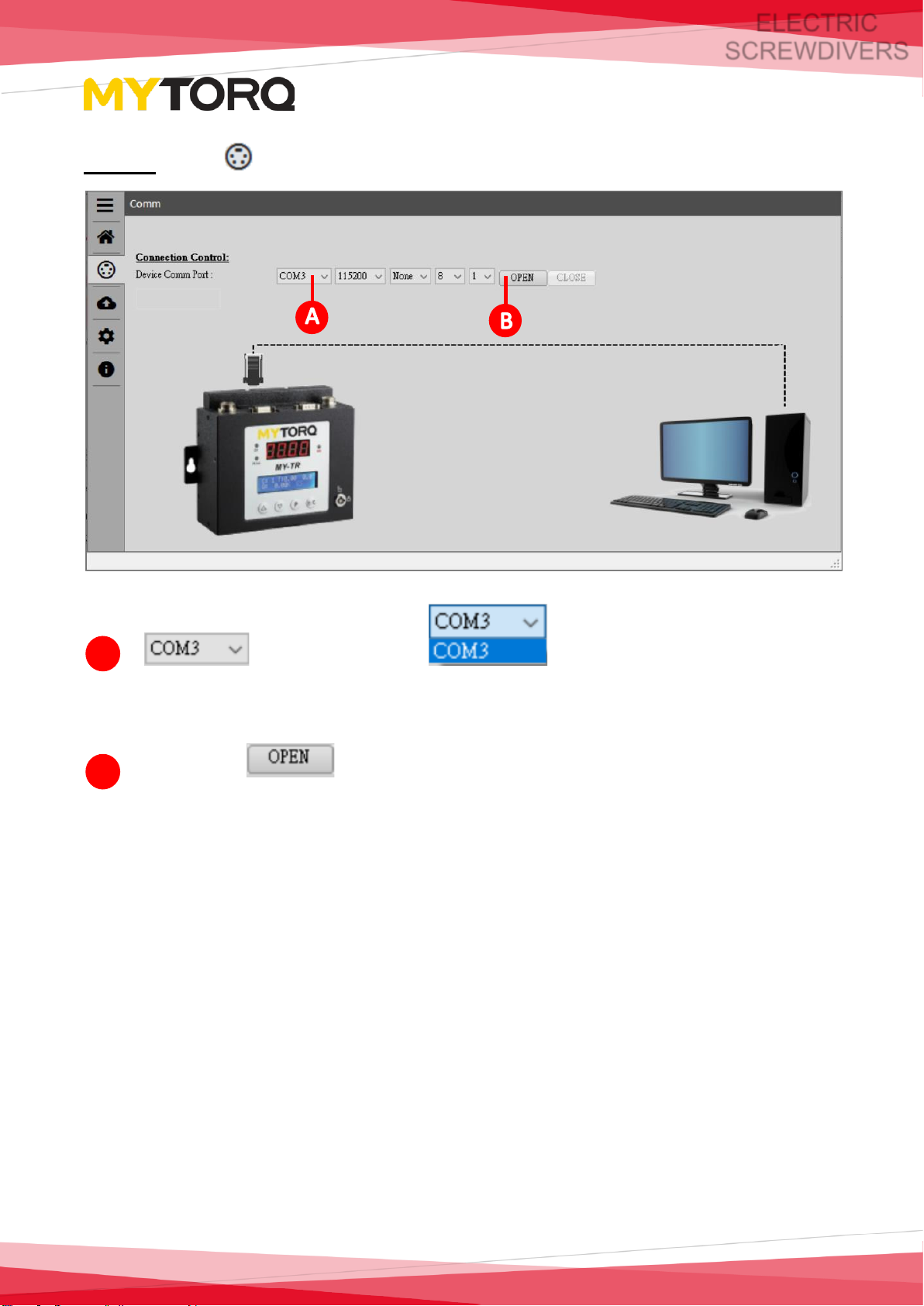
④System Connection.....................................................................................................................6
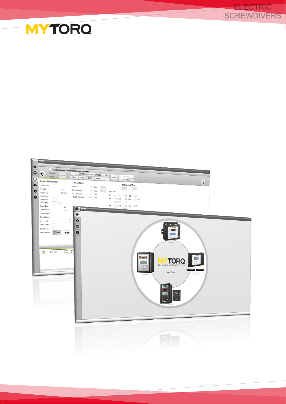
⑤System Screen Introduction ......................................................................................................9
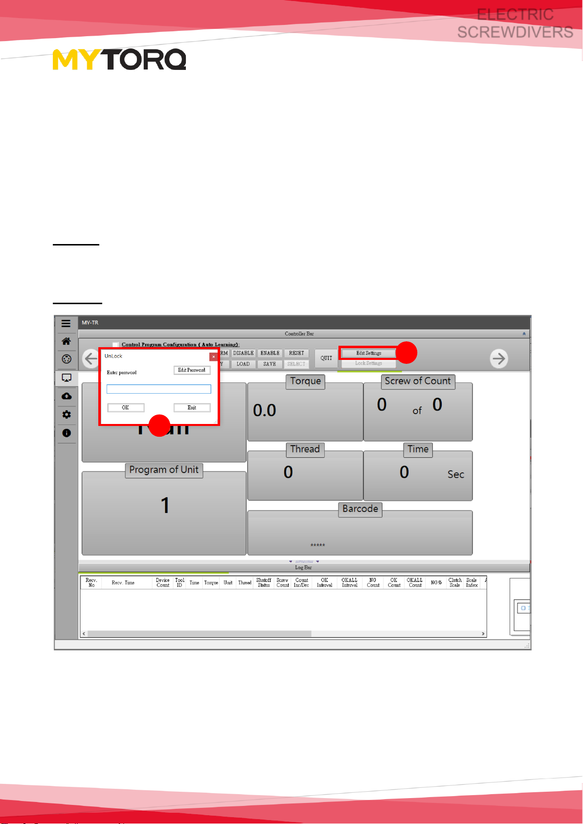
➢Unlock Settings....................................................................................................................9
➢Password change setting method...................................................................................10
➢Restore default password ................................................................................................10
1. Product setup page...........................................................................................................11
2. Controller and Job setup page.........................................................................................28
3. Barcode Manager................................................................................................................32
4. Report and trend graph setup page.................................................................................34
5. Instant data display.............................................................................................................37
⑥Remote Screen..........................................................................................................................38
⑦System Function Setup............................................................................................................39
⑧Info Company Website.............................................................................................................41
⑨Example Description.................................................................................................................42
⑩Statement...................................................................................................................................46

Page 3 of 46
ELECTRIC
SCREWDIVERS
①User Guide
This manual describes how to quickly operate the “Data Acquisition System”
and get started with the MY-TR controller.
Diversified operation interface, user-friendly design also system can have
functions such as report operation, data analysis, trend graph, parameter setting,
etc.

Page 4 of 46
ELECTRIC
SCREWDIVERS
②System Requirements
⚫Windows 10, Windows 8, Windows 7, Windows XP or Windows Vista
⚫Hardware memory at least 768MB/2GBHz processor
⚫At least 2GB hard disk
⚫Recommended at least 16-bit color and 1024x768 screen resolution
⚫.NET Framework 4.0 or above must be installed

Page 5 of 46
ELECTRIC
SCREWDIVERS
③Hardware
1. The following must be prepared before operating this system:
⚫MY-TR Controller
⚫Executable file for the operating
Data_Acquisition_System.exe.
⚫One RS-232 serial port.
⚫One 1D(Linear) barcode scanner (*not necessary).
2. Device connection as in the following diagram:
PC
Barcode scanner
PORT2
RS-232
RS-232
PORT1
MY-TR

Page 6 of 46
ELECTRIC
SCREWDIVERS
④System Connection
Step 1: Before log in, it is required to set the date format in the computer system
as “YYYY/MM/DD”.
Step 2: Download the compressed software
NOTE:
For the version: 1.0.0.6 and later on, there must have 2 additional dll files in the
folder(shown as below picture) after you decompressed the software. These are
required files to run the software.
Step 3: Open the executable file Data_Acquisition_System.exe.

Page 7 of 46
ELECTRIC
SCREWDIVERS
Step 4: Move the mouse cursor to and display the four
controllers.
Step 5: Controller selection (MY-TR)

Page 8 of 46
ELECTRIC
SCREWDIVERS
Step 6: Go to Comm page.
port to pull down
(Connect according to the port of the computer display device)
And press and leave controller product testing setup page
(communication settings are default, there is no need to modify).
A
B

Page 9 of 46
ELECTRIC
SCREWDIVERS
⑤System Screen Introduction
➢Unlock Settings
The page displayed is Instant data display after entering the screen. At this time,
no operation can be performed due to locked setting. You must enter the
password first if need to unlock for operation.
Step 1: After clicking the button of "Edit Settings", the unlock window will pop
up.
Step 2: Enter the default password "admin123" and click confirm button.
1
2

Page 10 of 46
ELECTRIC
SCREWDIVERS
➢Password change setting method
Click "Edit Settings" button → "Edit Password" to enter the old password and
the new password, and then click OK button to complete the setting.
NOTE: New password setting: Six to eight characters in length, including
English uppercase and lowercase, numbers.
➢Restore default password
Select to enter the Setting folder, delete the file named Setup and
Reopen it Data_Acquisition_System can restore the default password
(admin123)
2
3
1
1
2
3
1
2
3

Page 11 of 46
ELECTRIC
SCREWDIVERS
1. Product setup page: divide the setup page into partitions and
introduce them in order.
NOTE:
The pages of the system can be operated by sliding left and right , so the
software can be operated on the touch screen.
A
H
B
H
D
H
C
H
E
H
G
H
H
H
H
H
F
H

Page 12 of 46
ELECTRIC
SCREWDIVERS
Controller device setup
Introduce the functions for the two zones from left to right in order:
⚫Control Program Configuration (Auto Learning):Press and check
the check box , then the
user could Load or Write the parameters.
➢When the check box is unchecked
, all input fields are
shown as gray color which mean the user can't input any
parameters.
A

Page 13 of 46
ELECTRIC
SCREWDIVERS
➢When the check box is checked
, all input fields are
shown as white color which mean the user can input the
parameters.
⚫Program: Display the program group currently used (Program).
⚫Tool ID: Display the current used tool's id.
⚫CLEAR: Press to reset counting.
⚫CONFIRM: Press to dismiss controller C3 status.
(refer to User Manual for C3 function introduction).

Page 14 of 46
ELECTRIC
SCREWDIVERS
⚫DISABLE: Press to immediately stop screwdriver operation.
⚫ENABLE: Press to immediately allow the screwdriver to run.
⚫RESET: Press to restart the controller and restore factory
parameters.
⚫EDIT: Press to enter screwdriver condition parameters.
⚫COPY: Press to copy the TQC condition parameter to Program.
(Procedure: → →
tightening screws→ → → , After done this procedure,
the system will copy T, Q, C data to HT/ HQ/HC/LT/LQ/LC as limitations.

Page 15 of 46
ELECTRIC
SCREWDIVERS
⚫LOAD: To load the parameter settings from the MY-TR controller.
Press and check
and select program . Press to finish this process.
1
2
4
3

Page 16 of 46
ELECTRIC
SCREWDIVERS
⚫SAVE: Save the parameters to MY-TR controller.
Press and check
then input required parameters. Press and to finish
this process.
1
5
4
2
3

Page 17 of 46
ELECTRIC
SCREWDIVERS
⚫SELECT: Press and check
then input required parameters . Press and to
switch to required program.
⚫QUIT: Press to end after pressing .
1
5
4
2
3

Page 18 of 46
ELECTRIC
SCREWDIVERS
⚫Edit Settings:After entering the system, you must click
and enter the password to unlock the screen and switch to other pages.
(Please refer to "Password Change Setting Method")
⚫Lock Settings:Click to automatically jump to the "Instant
data display" screen, and no operation can be performed. The lock settings
must be unlocked.
(Please refer to "Instant data display" , "Unlock Settings")

Page 19 of 46
ELECTRIC
SCREWDIVERS
Received Data Display: All fastened data can be displayed instantly.
⚫Received Time: The time to fasten the data.
⚫Device ID: Device ID (1~255).
⚫Program Unit: This fastened program group (Program).
⚫Device Count: The total number of times the device is fastened.
⚫Sequence ID: Shows current sequence unit ID (1~8).
⚫Screw Count: The number of fastened units.
B

Page 20 of 46
ELECTRIC
SCREWDIVERS
⚫Shutoff Time: How long driver ran before clutch tripped. (Sec)
⚫Shutoff Torque: the torque for the fastening.
⚫Shutoff Thread: Number of rotations at output shaft.
⚫Shutoff Status: shut off status (OK, NG, OK ALL, REV).
⚫Device Mode: STD mode, ADV mode (please refer to manual).
⚫Device Status: (Refer to the “Display Status Code Description” in User
Manual).
⚫Barcode Data: barcode data.
⚫BarCodeEnable: The C3 function will be dismissed when the barcode is
scanned (refer to User Manual for C3 function introduction).
Other manuals for MY-TR
1
Table of contents