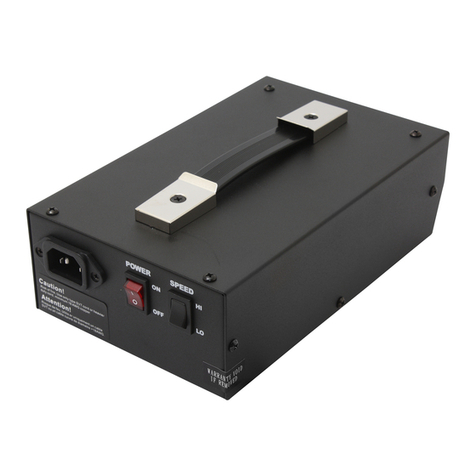
MYTORQ MYPC40-500 User manual


1
Metal Assembly Screwdrivers are designed for installing threaded fasteners in light industrial and appliance manufacturing
applications.
MYTORQ is not responsible for customer modification of tools for applications on which MYTORQ was not consulted.
Important safety information enclosed.
Read all these instructions before placing tool in service or operation this tool and save these instructions. It is the responsibility of the
employer to place the information in this manual into the hands of the operator. Failure to observe the following warnings could result
in injury. When using electric tools, Basic safety precautions should always be followed to reduce the risk of fire, electric shock and
personal injury, incl
1. General Safety Rules ……………………………………………………………………………… 1
2. Important Safety Instructions ……………………………………………………………………… 2
3. Operations Cautions ……………………………………………………………………………… 4
4. Main Technical parameters ……………………………………………………………………… 5
Control panel specifications………………………………………………………………………… 6
Functions of Keys on Pane l………………………………………………………………………… 7
I/O Inserting Hole ………………………………………………………………………………… 9
Functional Dip Switch ……………………………………………………………………………… 11
5. System Setting ……………………………………………………………………………………… 13
6. Simulated Learning ……………………………………………………………………………… 16
7. Grounding ………………………………………………………………………………………… 16
8. Servicing …………………………………………………………………………………………… 16
9. Explosive Drawing for Parts /Spare- Part List …………………………………………………… 18
NOTICE
WARNING

2
WARNING! Read all instructions Failure to follow all instructions listed below may result in electric shock fire and/or serious
injure. The term "power tool" in all of the warning listed below refer to your mains operated (corded) power tool or battery operated
(cordless) power tool.
SAVE THESE INSTRUCTIONS
1) Electrical Safety
a) Keep work area clean and well lit. Cluttered and dark areas invite accidents.
b) Do not operate power tools in explosive atmosphere, such as in the presence of flammable liquids, gases or dust. Power tools
create sparks which may ignite the dust of fumes.
c) Keep children and bystanders away while operating a power tool.
Distractions can cause you to lose control.
2) Electrical Safety
a) Power tool plugs must match the outlet. Never modify the plug in any way. Do not use any adapter plugs with earthed
(grounded) power tools.
Unmodified plugs and matching outlets will reduce risk of electric shock.
b) Avoid body contact with earthed or grounded surfaces such as pipes, radiators, ranges and
refrigerators. There is an increased risk of electric shock if your body is earthed or grounded.
c) Don’t expose power tools to rain or wet conditions.
Water entering a power tool will increase the risk of electric shock.
d) Do not abuse the cord. Never use the cord to carry, pulling or unplugging the power tool. Keep
cord away from heat, oil, sharp edges or moving parts.
Damaged or entangled cords increase the risk of electric shock.
e) When operating a power tool outdoors, use an extension cord suitable for outdoor use.
Use of cord suitable for outdoor use reduces the risk of electric shock.
3) Personal Safety
a) Stay alert, watch what you are doing and use common sense when operating a power tool. Do not use power tool while you
are tired or under the influence of drugs, alcohol, or medication. A moment of inattention while operating power tools may
result in serious personal injury.
b) Use safety equipment. Always wear eye protection. Safety equipment such as dust mask, non-skid
safety shoes, hard hat, or hearing protection used for appropriate conditions will reduce personal injuries.
c) Avoid accidental starting. Ensure the switch is in the off position before plugging in. Carrying power tools with your finger on
the switch or plugging in power tools that have the switch on invites accidents.
d) Remove any adjusting keys or wrench before turning the power tool on. A wrench or a key that is left attached to a rotating
part of the power tool may result in personal injury.
e) Do not overreach. Keep proper footing and balance at all times.
This enables better control of the power tool in unexpected situations.
f) Dress properly. Do not wear loose clothing or jeweler. Keep your hair, clothing, and gloves away from moving parts. Loose
clothes, jeweler, or long hair can be caught in moving parts.
g) If devices are provided for the connection of dust extraction and collection facilities, ensure these are connected and
properly used. Use of these devices can reduce dust related hazards.
4) Power tool Use and Care
a) Do not force the power tool. Use the correct power tool for your application.
The correct power tool will do the job better and safer at the rate for which it was designed.
b) Do not use power tool if switch does not turn it on or off. Any power tool that cannot be controlled with
the switch is dangerous and must be repaired.
c) Disconnect the plug from the power source before making any adjustments, changing accessories,
or storing the power tools.
Such preventive safety measures reduce the risk of starting the power tool accidentally.
Important Safety Instructions

3
d) Store idle power tools out of reach of children and do not allow persons unfamiliar with the power
tool or these instructions to operate the power tool.
Power tools are dangerous in the hands of untrained users.
e) Maintain power tools. Check for misalignment or binding of moving parts, breakage of parts and
any other condition that may affect the power tools operation. If damaged, have the power tool repaired before use. Many
accidents are cause by poorly maintained power tools.
f) Keep cutting tools sharp and clean, properly maintained cutting tools with sharp cutting edges are less likely to bind and are
easier to control.
g) Use the power tools, accessories and tool bits etc., in accordance with these instructions and in the
manner intended for the particular type of power tool, taking into account the working conditions and the work to be
performed.
Use of the power tool for operations different from intended could result in a hazardous situation.
5) SERVICE
a) Have your power tool serviced by qualified repair person using only identical replacement parts,
This will ensure that the safety of the power tool is maintained.
Additional information shall be provided.
a) Instruction for putting into use.
1. Setting-up or fixing power tool in a stable position as appropriate for power tools which can be mounted on a support.
2. Assembly
3. Connection to power supply, cabling, fusing, socket type and earthing requirements.
4. Illustrated description of functions.
5. Limitations on ambient conditions.
6. List of contents.
b) Operating Instructions.
1. Setting and testing.
2. Tool changing.
3. Clamping of work.
4. Limits on size of work piece.
5. General instructions for use.
c) Maintenance and servicing.
1. Regular cleaning, maintenance, and lubrication.
2. Servicing by manufacture or agent, list of addresses.
3. List of user-replaceable parts.
4.Special tools which may be required.

4
1. Please read the operating manual thoroughly and comply with safety regulation to operate this Multi-Function Controller.
2. Please grasp the plug of power cord while plugging in or out the plugs of connecting cord of Electric Screwdriver and power
cord.
3. Please fix the power controller to avoid any danger of pulling and dragging the power cord.
4. Do not near oil, chemical materials or heated objects, also please be alert not to scratch the power cord by sharp object.
5. This type of Controller can only be applied to MYTORQ Electric Screwdriver with Counter. Do not use Electric Screwdriver
Controller on other types of machinery.
6. In case of the Controller is overheated or overloaded with maximum current rating of fuse, the high-speed fuse will be melt down
and cut off the power. If the Controller continues to jump off or has an abnormal switching reaction, please stop the operation
immediately and send back the Controller for repair.
7. When Electric Screwdriver is running, if slides Forward/Reverse Switch instantly, device will generate the protection program to
force Electric Screwdriver stop.
8. Please do not disassemble Electric Screwdriver casually and try to repair it by self.
9. When Controller is not in use, please turn the main power switch OFF and unplug the power.
10. The electric frequency will be lower when the voltage is adjusted as Lo or below 32V, so the torque of the electric screwdrivers
can't be worked out except below scale of 4.
*Please arrange to use the whole set of Electric Screwdriver MY2 MY5 MY7 MY8 MYT MYR series except MY2 MY5 MY7
MY8 MYT MYR series with the Multi-Function Controller.
*Please arrange to use together with MYTORQ MY2 MY5 MY7 MY8 MYT MYR series Electric Screwdriver. If operator uses
different brand of Electric Screwdriver and repair tools with parts or accessories not from MYTORQ manufacturer, it may cause
the Controller malfunction or poor quality. As a result, all of product guarantees will be void and no obligation to the
manufacturer.
*When Electric Screwdriver is running, if operator slide Forward/Reverse switch instantly, device will turn on the protection
program to force the Electric Screwdriver stop running.
*Don't switch HI/LO changeover button when the screwdriver is running.
*To plug or unplug the DC connector must wait the LED OFF after power off.
CAUTION
Operations Cautions

5
※MY2-0235LS5 can’t work with slow start (RC / SP) function.
※MY2 MY5 MY7 MY8 MYT MYR series must be used with SIX PIN screwdrivers, so please confirm the screwdriver’s type is
MY2 MY5 MY7 MY8 MYT MYR series and the connector is SIX PIN when using.
Step of the screwdriver confirmation:
1.Confirm the sticker is " MY " type.
2.Confirm the screwdriver’s CONNECTOR type is SIX PIN.
3.Confirm the connect cable between screwdriver and power controller is SIX wires.
Model No MYPC32-100 (Ver:4.0) MYPC40-500 (Ver:4.0) MYPC40-1500 (Ver:4.0)
Input Voltage AC 100-240V 50 / 60Hz AC 100-240V 50 / 60Hz AC 115/230V 50 / 60HZ
Output Voltage DC 32V/ 24V DC 40V/ 32V/ 24V DC 40V/ 32V/ 24V
Power Consumption 60W
220W
360W
Counting Numbers 1~99
Counting Method Forward as / Count down
Connecting Sensor ON / OFF
Sensing Switch Mode ON (2 Sensor) / OFF (1 Sensor)
Slow-Start Time Adj. 0.0~9.9 seconds
Slow-Start Speed Adj. L0:100%,30%~90%L1~L9 Rated speed
Start Detecting Time 0.01-9.99 seconds
Stop Detecting Time 0.1-9.9 seconds
Detecting Alarm ON/ OFF/ FF/ EF with LED and buzzer
Auto response/Manual response
ON / OFF
External Connection Input Forward / Reversion / Prohibit operation / Sensor Switch / resuming Switch / Confirm Switch
External Connection Output OK/ NG/ OK ALL
Electric Screwdriver Speed
Control
HI / LO;Slow Start
Size (mm) 200*130*100 247 *130*100
Weight (Kg) 1.53 2.4
Applicable Electric
Screwdrivers
MY2-0235L;MY2-0235LS5;
MY2-0235LS6;MY2-0235LS7
;MY2-0507L;MY2-0110L;
MY2
-
0210
P
MY8-0205L;MY8-0205P;
MY9-0206L;MY9-0206LF;
MY9-0309L;MY9-0612L
MY5-0212L;MY5-0212P;
MY5-0212LF;MY5-0212PF;
MY5-0319L;MY5-0319P;
MY5-0317LF;MY5-0317PF
MYT-0320L;MYT-0830L;
MYT-0205L
MYT-0103LF;MYT-1235LF;
MYT-0205LF;MYT-2507L
MY7-1030L;MY7-1030P;
MY7-0522LF;MY7-0522PF
MYT-0206L;MYT-0309L;
MYT-0412L;MYT-0618L;
MYR-0206L;MYR-0309L;
MYR-0412L;MYR-0412LF;
MYR-0618L;MYR-0618LF;
MYR-0825L;MYR-0825LF;
MYR-1235L;MYR-2050L;
MYR-0206P;MYR-0309P;
MYR-0412P;MYR-0412PF;
MYR-0618P;MYR-0618PF;
MYR-0825P;MYR-0825PF;
MYR-1235P;MYR-2050P
Accessories Power cord *1、Key *2
Main Technical parameters

6
NO.
PARTS NAME NO.
PARTS NAME
1 LED Indicator 12 Down-Selecting Key
2 HI / LO Speed Switch 13 System Build-in Reset Key
3 Key setting lock 14 POWER/CLEAR Key
4 6Pin Connector 15 Functional Selection / Confirm Key
5 WORK Light 16 Power point
6 OK Light 17 POWER SWITCH
7 N.G Light 18 Output voltage choice
8 24V Light 19 I/O Inserting Hole *Instruction
9 32V Light 20 Functional Dip Switch *Instruction
10 40V Light 21 GND
11 Up-Selecting Key
Control panel specifications

7
Functions of Keys on Panel:
Key Description of function. Remarks
POWER:Power Switch
(1) Press and hold for 6 seconds that will turn off counter and other functions including 7 segment.
LED display.
(2) Press and hold for 3 seconds to turn counter back on when counting function is deactivated.
CLEAR:Clear Switch
When operator intends to reset counter during operation, simply press and hold for one second till
beep once. But under a cycle mode, to return back U1 for resetting by pressing and holding keypad
for 3 seconds till beep twice.
Switch page:Under setting menu will change pages of decimal point
When there is NG signal,
press CLEAR bottom to
clear the NG signal
SELECT:
Press and hold SELECT button for 3 seconds to enter system setting menu:
SL---- SC----At----Ot----Rc----SP-----Ht----Lt----LL----NS----Ut----rt----rr----rS
When enter the setting menu. Press and hold S button to show the function (ex:SL or SC…etc.)
and with beep sound. Release the "S" button to show the setting value.
CONFIRM:
When DIP SW3 ON, when the user finished fastening a unit of screws. The counter requires to
press CONFIRM button to start the next unit.
1. Refer to CONFIRM
mode:
When there is NG signal
output. Press "CONFIRM"
button to stop the NG signal
output.
UP:
In system menu, pressing the key to increase the number.
This key will point out user set-up number and unit during the process :
U1:No.1 setting number. U2:No.2 setting number.
U3:No.3 setting number. U4:No.4 setting number.
U5:No.5 setting number.
When press the UP button
(hold), then panel will show
the unit number, then press
the start plate and the
screwdriver will not operate
DOWN:
In system menu, pressing the key to decrease the number.
This key will point out user set-up number and group during the process :
U1:No.1 setting number. U2:No.2 setting number.
U3:No.3 setting number. U4:No.4 setting number.
U5:No.5 setting number.
When press the DOWN
button (hold), then panel
will show the unit number,
then press the start plate and
the screwdriver will not
operate
+
Up+Down:
Select the following modes.
When fastening screw, compl
eting work and
if mistaken operation, the buzzer sound will
be on.
warring beep when finish all
screws in the list and error in
operation
Only beep warning when wrong operation
As one screw is fastened and work
is completed, buzzer will be on;
wrong operation will be no sound.
S.RESET:SYSTEM RESET
Because of voltage or operation cause system abnormal, push this key back to the initial number.
The S.RESET is not functional if the outer key is under LC mode.
Press RESET key once then
release. When hold RESET
key, the screwdriver is not
able to operate until the
release the reset button.
+
Lock function of the Panel Lock
Unlock function of the Panel Lock

8
+
Enter the setup:dt----- tt-----Sr----SA----Gr-----Rn
dt/tt
dt:the time range between each screwing process. This function will be triggered after finish one
screwing process. If user doesn’t start next screwing process in this setting time range. The system
will display "dt" until next screwing process is started. ("01"= 1 second)
tt:All the screwing processes in this list need to be finished under this setting time range. If user
didn’t finish all the screws in this setting time range, the panel will display "tt" until all the screwing
processes are finished. ("01"= 1 minute)
Note:
(1) When dt errors, restart the screwdriver will release from error status. If two or more errors
occurs,
the red light up and buzzer sounds, LED screen will display other error messages.
(eg:NS);To solve other errors first and the red light will turn off, but dt continued errors.
(2) When tt error occurs, to complete all fastening process will be released from tt error
condition. If an error occurs while there are other error coexist, same as dt situation.
(3) When multiple loop mode:
dt is for every one small loop (U #, #:1,2,3,4,5), for each fastening screw time interval.
tt is for the time of one big loop (U1 ~ U #, #:2,3,4,5), which is from U1 first start until the
end of last U # screw is fastened.
(4) When the dt / tt occurs, press CLEAR to release from dt / tt , counter will return to the original
screw numbers setting of the current unit
Sr:Multiple function switch cycle SENSOR
Y:multiple cycles (SW2 = ON, SW6 = ON), when the number of fasten screws U1 are complete
then screwdriver stop until the sensor triggered (SW4 = OFF). If SW4 = ON, you need to trigger
twice before jumping to U2 ... and so on
N:multiple cycles (SW2 = ON, SW6 = ON or SW2 = ON, SW4 = ON, SW6 = ON), when the
number of fasten screw U1 are finish will automatically execute At time of that unit, then
automatically start unit 2.
Sr default:N
Gr:
When Er occurs, selects Y without “CONFIRM” to disable. If selects N be sure to press
“CONFIRM” to disable.
For example, when C4 & C5 trigger to Er signal, if Gr = Y happens the “CONFIRM” should be
ignored which means an Er occurs that is the normal trigger at this situation.
※ When Gate_SW2_OFF_Err occurs, user must have a “CONFIRM” to disable. When C1, C2, C4
& C5 are under stage of Er, SW = OFF shuts off which means there is only “CONFIRM” can help to
disable.
Rn:
Selects Y: this will enable the function of reversing to resume. See SW7 status below:
SW7 ON = for reversing to resume to preset of screw’s quantities
SW7 OFF = for reversing to resume only once
Selects N: disable the function of reversing to resume and SW7 (ON/ OFF) is futility.
Note:When SW6 = ON, Sr parameter setting (Y / N) only for reference. That is, Sr is a global
variable, once SW6 = ON;Sr can set Y or N,
then U2 ~ U5 SENSOR mode will follow same setting
SA:When under Sensor mode, SA parameter setting only effect when the SW2 = ON, SW4 = OFF.
The up and down button in the front panel can switch value (HI / LO).
HI:Hi Active LO:Lo Active The default value is:HI
Note:
(1) When the user presses the
POWER + UP, panel displays
dt, release POWER + UP to
show up values. At the dt
mode, pressing "S" key can
set "tt" value. Repeating press
"S" key for the following
setting.
"Sr" “SA” “Gr”
“Rn”
(2) dt and tt cannot be
coexisted. When value sets as
dt > 0, tt will disappear. The
same, when the tt > 0, the dt
will disappear.
Unlock Function
Lock Function
1.Lock with the key (Need use the key to lock
2.When KEY lock is in lock position, the user changes the Hi/Lo speed setting, the LED will
display
"
PC
"
and the counter will beep 8 times until user change back the Hi/Lo setting.

9
I/O Inserting Hole:
※CN1(V+) and CN14(COM) can provide DC 24V(Default)。(DC +12V need to custom modify)
※If users need different DC voltage, they must use their own step-down circuit to decrease voltage.
※If user need to input voltage to drive the alert instrument, do not use over DC+/-40V /, +/- 250mA voltage.
No Name In/Out
Content wave pattern of signals Remark
CN1 V+ Output 12 or 24 v dc
Output:DC +12V or +24V (Max:200mA)
Default value:+24VDC
(+12VDC need to
custom modify
)
CN2~CN3
OK Output
CN2 and CN3 will be short
when finished fastening one
screw
Automatically open
MOS RELAY (default) +/- 40V, +/- 250mA
(Open Collector need to custom modify)
CN4~CN5
NG Output
CN4 and CN5 will be short
when error occur
Automatically open
MOS RELAY (default) +/- 40V, +/- 250mA
(Open Collector need to custom modify)
CN6~CN7
OK ALL
Output
CN6 and CN7 will be short
when finished fastening all
screw in the list
Automatically open
MOS RELAY (default) +/- 40V, +/- 250mA
(Open Collector need to
c
ustom modify
)
CN8 START_IN
Input External START input
1.When short Start input and COM(CN14) (CLOSE
circle), able to start the screwdriver
2.When open circle with COM(CN14)
, screwdriver stop.
CN9 DIR_IN Input External REVERSE input
Shorten with COM (Close circle) and when enable start
signal (CN8 + COM), screwdriver will start with
Reverse rotation.
If the driver switches F/R switch on "forward", when
CN9 + COM short screwdriver is still reversed rotation
after start
CN10 DISABLE
Input External DISABLE input
When short with COM (CLOSE circle), cannot start the
screwdriver.
When open circle with COM, screwdriver is able to start.
* When DISABLE (shorted with COM), work LED
lights ON for 5 seconds, then OFF, then light up again
for 5 seconds, on an
d
off in circle.
CN11 CONFIRM
Input External CONFIRM input
This switch feature and function is the same as
CONFIRM, but no SELECT key function.
After press CONFIRM the NG signal will be release.
CN12 GATE Input External sensor switch
SW2:ON SW4:OFF
SW2:ON SW4:ON
Input a confirm signal for machine to start working.
Sensor Switch:External
device, you can connect one or
two switches.
CN13 CLR Input External device CLEAR
switch
External clear switch, same as clear button on the panel.
It also can disable N.G signal when it is triggered
CN14
COM
-
CN8 ~ CN13output/input signal COM port

10
Terminal Connecting Diagram:(To take factory default:MOS RELAY I/O for example)
Output:
Input:

11
Functional Dip Switch:
Instruction:
SW1:Selects ON, counts screws number forward as 1-----2-----3------4------5-----------------1…
Selects Off, count down the screws number as 5-----4-----3-----2------1-------------------5…
SW2:Sensing Switch, select ON means Counter needs external sensing switch, MYPC40-500 must be in
accordance with the sensing switch mode to determine if electric screwdriver will work. Select OFF
means unnecessary for external switch, count number don’t have to consider external switch to
determine if it works.
Note
:
SA settings will affect SW2 = ON, SW4 = OFF the SENSOR drive mode, please refer to the SA
setting for detail information.
SW3:The Count number Reset Mode, when counting screws number reach to the setting value, counter must be reset to default
value, if select ON which stands for manual reset, user must press "SELECT/CONFIRM" / external CONFIRM (CN11+CN14)
Key on the panel back the setting count number, otherwise Electric Screwdriver is unable to start under no confirming situation
on the device. Select OFF makes system automatically to recover from the setting count number.
SW4:Switching Mode:Select ON means the external SENSOR need to have two signals been sent to MYPC40-500 which stands
for the fastener on operational process need to go through the sensor on machine table to identify the fastener has been
removed from working table, and new fastener goes through another SENSOR for confirming the new fastener that has
reached the working table. Therefore two confirming signals allow S MYPC40-500 to start the Electric Screwdriver running.
Select OFF means only need one SENSOR to confirm the fastener that has been removed from this working table;this allows
Electric Screwdriver starts to work.
SW5:Auto-Learning Mode: The Counter counts screws number and sends OK & NG signals followed by Ht/ Lt settings. Thus,
Auto-Learning Mode experiences and memorizes screw fastening time from beginning to the end. To do so, simply user
switches this mode to ON, and then system will ask fastening position (SL), number of screws (SC) to be tightened, whether
needs time to be changed back to default or not (At), and OK LED keeps displaying time (Ot). Besides, user can add slow start
function (Rc) or select speed level (SP), if need.
SW6:Arrangement form:The memory can save five units number, user can push switch ON, the system will automatically arrange
five units, easy for user to make arrangement at work.
SW7:Reverse Resuming:User can turn on the reverse resuming switch to lose screws back. The system is able to count backward for
presetting quantity of screws to be fastened. If the reverse resuming switch is switched to off, the system is only to do
countdown for the last screw.
Note:Multiple cycles (SW6:ON):
(1) rr =0
Whether Sr = Y or Sr = N, the reverse will both added to the U1.
(2) rr>0:
The screw list set with rr;the screwdriver well not reverses and will not add screws on the screw count.
At this point the user press CLEAR button or use CN13 to clear the count value to solve the problem and restart the
operation after the "new work.
If customers want to reverse all screws, please turn off the counter before start reverse.
SW
Name
OFF
ON
1
Counting Mode
Count
Backward
Count Forward
2
Sensor Switch
Stop
Work
3
Manual Confirm Mold
Auto Zero
Start the Manual Confirmation
4
Switching Mode
Once
Confirm
Twice
Confir
m
5 Automatic simulation
learning mode
Stop Work
6 Units’ arrangement
Mode
Stop Work
7 Reverse resuming only one screw
count backward
Enable to count backward within
the screw’s quantity setting

12
CONFIRM :
Code
Instruction Notations
First external sensor to be confirmed.
SW2 (ON) + SW3 (OFF) + SW4 (OFF)
External sensor
* When the SA is set to HI, the display
"C1";if set is LO and will displayed "C.1 "
The second external sensor to be confirmed.
SW2 (ON) + SW3 (OFF) + SW4 (ON)
※When error occurs, the sensor needs to be triggered again. At this
moment, panel shows "Er", user must press the "CONFIRM" from panel
or short circuit (CN11 + CN14 ports) to clear "Er".
External sensors
Manual confirm the panel.
SW3 (ON)+SW2(OFF)+SW4(OFF) Panel / External CONFIRM
A switch SENSOR confirm +confirm button on the panel or short circuit
CN11+CN14
SW2(ON)+SW3(ON)+SW4(OFF)
External sensor + Panel / External
CONFIRM
* When the SA is set to HI, the display
"C4";if set is LO and will displayed "C.4 "
Two switch SENSORS confirm + confirm button on the panel or short
circuit CN11+CN14
SW2(ON)+SW3(ON)+SW4(ON)
External sensors + Panel / External
CONFIRM
Reset to the default setting. CLEAR
Error Code on LED description:
Symbol Definition Description
High Temp. Protect 1.Screwdriver will stop when the operation temperature is higher.
2.LED will display [E4] to indicate high temperature protect.
Stall Protect 1.Screwdriver will stop when motor is abnormal stalled after start.
2.LED will display [E5] to indicate stall protect.
Push plate Error 1.Screwdriver will stop when push plate change between motor running.
2.LED will display [E7] to indicate abnormal operation.
Brake Error 1.Screwdriver will stop when the abnormal brake signal appeared before start.
2.LED will display [E8] to indicate abnormal brake error.
Power Error
1.When key is turning to lock, the voltage value has been changed in the meantime, the
panel shows up PC status. (8 beeps)
2.A PC shows up when the controller outputs an invalid voltage to electric screwdriver.
(e.g. When 24V is the output setting, we still connect a DC 40V screwdriver that does
not match to each other. There will come 3 beeps warning (It is the same sign as low
voltage) and NG light on.
3.When screwdriver connects to controller, there will need 2 seconds detecting time. (A
PC shows up during these 2 seconds)
※ The error when the screw fastened was occurred during the external mode confirmation, the
system will detect the abnormal state. The LED will show error code and the buzzer
will ring. The operator must confirm the external sensor (CN11+CN14) or press CONFIRM.

13
※ If using three units of data only and let three units in cycles. It can set up "00" in counting number on U4, when
SW6 switch ON, the system will automatically move in circle from
U1~U3.
System procedure:
PROCESS TO SET UP SYSTEM:
1. Please connect the cord, turn on the power switch until LED shows number.
2. Please press SELECT key over three seconds till buzzer making sound, the panel will show ,
to push UP/DOWN to decrease or increase the number, it can set up five units of number.
3. To press SELECT key, buzzer will sound, the panel will show , to push UP/DOWN to
decrease or increase number, the maximum can set up 99.
SC:To set up counting number.
4. To press SELECT, the screen will show , push UP/DOWN to increase or decrease
number, the maximum can set up 9.9.
At:Automatic set up CLEAR time.
5. Presses SELECT to select and then press UP/DOWN to change digits. The maximum digit is 9.9.
Ot: LED time of OK or OK ALL status.
6. To press SELECT, the screen will show , push UP/DOWN to increase or decrease
number, the maximum can set up 9.9.
Rc:To set up slow-start time.
7. To press SELECT, the screen will show , , push UP/DOWN to increase or decrease number
between L0~L9, the maximum can set up L9.
SP:To set up speed of slow start.
8. To press SELECT, the screen will show , push UP/DOWN to increase or decrease
number, the maximum can set up 9.9.
Ht:Stop time.
9. To press SELECT, the screen will show , push POWER key, adjust decimals ,
push UP/DOWN to increase or decrease number, the maximum can set up 9.99.
Lt:Set up Detect Start Time."02."means 0.02.
10. To press SELECT, the screen will show , push POWER key, adjust decimals ,
push UP/DOWN to increase or decrease number, the maximum can set up 9.90.
LL:No times confirmed within set-up time after fastening. "02." means 0.02.
11. Press SELECT for show on LED and press UP/DOWN for change the setting.
NS:choosing action or not for next screwing process when error occur during screwing.
N:unlock(default setting) Y:lock (need to press S for release)
System setting
SL<SELECT>SC<SELECT>At<SELECT>Ot<SELECT>Rc<SELECT>SP<SELECT>Ht<SELECT>
Lt<SELECT>LL<SELECT>Ns<SELECT>Ut<SELECT>rt<SELECT>rr<SELECT>rS<SELECT>SAVE

14
12. Presses SELECT to select and then press UP/DOWN to change digits. The maximum digit is 9.9.
Ut: Pre tightening time; any escaped time less than Ut will be counted as NG failure.
13. To press SELECT, the screen will show , , push POWER key, adjust decimals , push UP/DOWN to
increase or decrease number, the maximum can set up 9.99.
rt:Set up auto reverse time。
14. To press SELECT, the screen will show , , push POWER key, adjust decimals , push UP/DOWN to
increase or decrease number, the maximum can set up 9.99.
rr:Set up auto forward time.
15. To press SELECT, the screen will show , , push POWER key, adjust decimal , push UP/DOWN to
increase or decrease number, the maximum can set up 9.99.
rS:Set up automatically forward pause time.
Remark:
(1) When RC = 0 or SP = L0, there will be no slow start function.
(2) When RC & SP/ LL are excluded in setting, there is only one setting allowance.
(3) When rt/ rr & rs/ LL/ Ut are excluded in setting, there is only one setting allowance.
Function Name
Set up Time
and Value Description Buzz Time/ Light Manufacturer
Set-Up Value
SL 01~05 Screw List --- ---
SC 01~99 Counting number / count-down only --- 05
At 0.0~9.9 Automatic zero time / Signal output time --- 1.0
Ot 0.0~9.9 LED time of OK or OK ALL status. --- 0.0
RC 0.1~9.9 Slow start time --- 0.0
SP L0~L9 Speed of start:L0:100%, L1~L9 (30%-90%) Rated speed --- L0
Ht 0.0~9.9 Ht time Stop time (Show wrong as screwdriver can’t stop at set
time after starting, can be used to test stripped screws
3 beeps come with red
LED on permanently
2.0
Lt 0.0~Ht Lt time will show wrong as screwdriver stops before Lt after
starting, can test screw is not properly fastened at its position. .
3 beeps come with red
LED
on per
manently
0.00
LL0.00~9.99
Reconfirm time after fastening. --- 0.00
NS Y / N Choosing action or not for next screwing process when error
occur during screwing. LED show NS N
Ut 0.0~9.9 Pre tightening time; any escaped time less than Ut will
be
count
ed
as
NG fai
lure
--- 0.0
rt 0.00~9.99
Auto reverse time/ When the torque is reached, and the
screwdriver will start to reverse (backward) in this setting rt time
range. (NOTE: rt value must exceed 0.05)
--- 0.00
rr 0.00~9.99
Auto forward. when F/R switch is reverse (backward), set the
number of seconds first for reverse immediately brakes and pause
ti
m
e r
S
.
then forward un
til the torque is reached.
--- 0
rS 0.10~9.99
Automatically forward pause time. When rr are setting (> 0), will
show
rS.
--- 0.10
Backward to
Count
-
Up
1 COUNT When screwdriver is backward, the number will be back one --- ---
Ln --- Automatic learning. LED keeps flash of light ---

15
Data Chart:
Execute under general pre-set program:
Start
*If the screwdriver stop time is in dotted line. it is normal fastening. "OK" will be shown.
*If the screwdriver stop time is before Lt or over Ht stop is before Ht or over Lt, it is "N.G.".
*User can freely adjust Ht. However, if Ht and Lt is closer, it will request more precise.
*If the user press the push button of the screwdriver after Ht and Lt setting, it is "N.G".
Ht/Lt mainly set up the period of time. If stop is within the set period, it means OK. In contrast, it
will be (NG), as stop before Lt or after Ht. and should reconfirm whether wrong screws is taken.
More precise requested means more correct Ht/Lt set-up should be. The Lt default value: 0.00,
but it can be increased or decreased in SELECT.
STOP
Lt
0.02 s
Ht
2.0 s
If screwdriver stops before Lt.
If screwdriver has no stop after Ht.
N.G
It is “OK” as
screwdriver stops
between Lt and Ht.
Screws stuck or wrong screws Screws stripped or wrong screws
N.G
OK
STAR
Lt
=0.02
Ht=2.0
L
L
=1.0
OK
N.G N.G

16
1、The switch mode SW5 change into ON.
※When SW5 change to ON, it will force to enter simulated learning procedure, any function will not work.
2、When it changes to ON, LED will flash. The user can set whether or not counting screws, starting slow start. The simulated
learning function will be turned on after this necessary condition confirming.
------------------------------------------------------------------------------------CHECK
3、When set up finish, LED will show 0.0 and the user can test to fasten screws, when screwdriver starts, LED will show the
count. When screwdriver shut-off, that means time to fasten screws. User can proceed many tests until satisfaction. User can
change SW5 switch to OFF, the system will set up Ht time automatically. (Note:Lt will be set to zero)
4、If user does not satisfy number, user can change SW5 to OFF, push SELECT over three seconds, then enter menu to change.
System procedure:
When use Electric Screwdriver Controller, it should be grounded to avoid operator getting electrical shock. This controller is equipped
with 3 leading wires and 3 pins of grounding plug to fit for grounding type of outlet. The grounding wire must be connected firmly
with power supply equipment for effective grounding result. The leading wire with yellow-green color is a grounding wire. Never
attempt to connect this yellow-green color wire on electrified connector, this Controller has built-in grounding wire with electric
leakage safety grounding and additionally, the Controller can eliminate ESD static, which is produced by running the electric
screwdriver, via grounding wire.
Maintenance and Inspection :
1. The controller must be operated in top condition, one day working hour must be not more than eight hours.
2. Please note don’t let the controller get over heated, every minute use 10~15 screws to operate.
3. The frequency use of this electric screw driver is over eight hours a day, still it needs periodically testing
and treatment. Every 5-6 months.
Simulated Learning
Servicing
Grounding
SL<SELECT>SC<SELECT>At<SELECT>Ot<SELECT>Rc<SELECT>SP<SELECT>Ht<SELECT>
Lt<SELECT>LL<SELECT>Ns<SELECT>Ut<SELECT>rt<SELECT>rr<SELECT>rS<SELECT>SAVE

17
1. The use of other than genuine MYTORQ replacement parts may Result in decreased tool performance and increased
maintenance, and may invalidate all warranties.
2. All repairs and maintenance of this tool and its word must be performed by an authorized service center.
3. MYTORQ is not responsible for customer modification of tools for applications on which MYTORQ was not consulted.
4. Repairs should be made only by authorized, trained personnel. Consult your nearest MYTORQ authorized service center.
5. It is the responsibility of the employer to place the information in this manual into the hands of the operator.
DO NOT ATTEMPT TO REPAIR THIS
ELECTRIC SCREWDRIVER
SAVE THESE INSTRUCTIONS
DO NOT DESTROY
CAUTIO
N
CAUTION
Our company reserves the right to modify
the product without prior notice.

PRODUCTION NO.
THIRD ANGLE PROJECTION.
ITEM NO:
DES. BY
CHKD.BY
APPD.BY
TITLE:
CUSTOMER DWG NAME
DWG NO:
MATERIAL
DATE
DATE
DATE
UNIT
SHRINK
SCALE SHT NO.
OF SHTS.
4
3
6
9
36
22
23
10
25
35
27
11
12
13
15
14
7
2
18
26
44
46
21
37
24
28
17
16
8
34
5
38
47
19
39
40
42
20
33 32
29
8
30
31
31
33
29
30
41
16
45
43
MYPC32-100 (V4.0)
MODEL:
This manual suits for next models
2
Table of contents
Other MYTORQ Controllers manuals