N.KO UZ 12 Ultralight Specification sheet
1
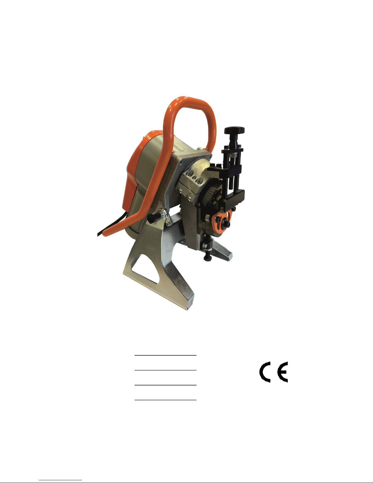
Machine for Bevel Chamfering with a Variable Angle
and Automatic Feed
NKO MACHINES
UZ 12 Ultralight
Instructions for Use and Maintenance
Customer
Model
Serial number
Year

2
Table of Contents
1 General Information
Introduction 3
Tests 3
Warranty 3
Identification Data 4
Reference Standards 5
2 Safety
Safety Considerations 6
Qualifications and Protection of Operators 7
Safety Devices 8
Other hazards 9
3 Technical Specifications
Machine Description 9
Technical Data 10
Noise Level 11
Working Conditions 11
4 Installation
Transport and Hoisting 11
Setting Up and Connection 12
Checks before Commissioning 14
Destruction and Disposal 14
5 Use
Proper Use 15
Description of Control Elements 15
Setting 16
Chamfering / Bevelling 21
Using a Pipe Adapter 23
6 Maintenance and Adjustment
Recommendations 25
Changing the Oil 25
Changing the Tool 26
Calibration of the Machine 27
7 Technical Diagrams
Wiring Diagram 27-29
8 Spare Parts
How to Order Spare Parts 29
Drawing Diagram of Spare Parts
List of Spare Parts 30 - 37

3
1.1. General Information
1.1 Introduction
Thank you for purchasing one of our machines and we hope that you will be fully satisfied
with it.
This manual contains all instructions for installation, adjustment, operation and maintenance
of the UZ12 Ultralight machine in accordance with the applicable safety standards.
Information contained in this manual may be subject to changes due to further
improvement of machines. In order to get rid of any doubts, please contact N.KO if you
find any differences.
Never carry out any operations with the machine until you read the instructions contained in
this manual and understand them. The majority of accidents which happen in the workplace
are caused due to failure to comply with instructions and recommendations contained in the
manual.
Graphic symbols used in the manual are used for highlighting of important information
concerning safety and operation of the machine.
Caution:
Important information for personal safety of operators.
Important:
An instruction which must be followed to ensure the correct operation of the machine.
1.2 Tests
The chamfering machine is tested in our testing laboratory.
Correct function of the electrical system and the correct bevelling function of sheets and
profiles of various types and dimensions are subject to the test.
1.3 Warranty
The seller grants the warranty that the bevelling system UZ 12 Ultralight will not have any
material or manufacturing defects for the period of 5 years from the date of delivery of the
goods.
The warranty for flawless function of the goods and the materials used is granted for the
period of 5 years from the date of delivery of the goods.
The seller undertakes to remove any possible defects covered by the warranty free of charge
and without undue delay, so that the buyer of the goods can use the product properly. Should
the buyer exercise rights arising from the liability for the defects which are not covered by the
warranty, he/she shall pay all related costs to the seller.

4
The warranty period does not run from the date when the buyer reports the defect covered by
the warranty and due to which the buyer cannot use the goods to the seller, thus exercising
his/her rights arising from the liability for defects covered by the warranty, until the date of its
removal by the seller.
The warranty does not apply to natural and common wear and tear of the goods and defects
caused due to improper use of the goods contrary to the provided training and documentation.
Furthermore, the guarantee does not apply to defects caused due to overloading of the goods
or to defects caused after unprofessional intervention in the goods or unprofessional repair or
modification to the product. The unprofessional intervention, repair or maintenance shall
mean any intervention, repair or maintenance carried out contrary to the provided training of
documentations or carried out by a person other than the seller or a person authorized and
approved by the seller.
The rights arising from the liability for defects covered by the warranty shall be exercised at
the seller without undue delay after the seller finds out the defect, but no later than the end of
the warranty period; otherwise these rights void.
The warranty card must be submitted upon exercising of rights arising from the liability for
defects covered by the warranty; otherwise these rights cannot be conferred upon the buyer.
Seller’s liability for defects covered by the warranty does not arise if these defects are caused
by external events. These external events shall mean, in particular, a natural disaster, force
majeure or actions of third parties.
N.KO considers the warranty invalid in the event of:
• improper use of the machine,
• use contrary to national or international standards,
• incorrect installation,
• faulty power supply,
• serious deficiencies in maintenance,
• unauthorized modifications and/or interference,
• use of wrong or other than genuine spare parts and accessories intended for the
respective model,
• total or partial non-compliance with the instructions,
• exceptional events, natural disasters and others.
1.4 Identification Data
The identification data of the machine for bevel chamfering are stated on the CE rating plate
attached to the engine case.

5
1.5 Reference Standards (EC Declaration of Conformity)

6
2.0 SAFETY
2.1 Safety Considerations
Caution:
Acquaint yourself thoroughly with the following instructions to avoid personal injuries
and/or damages to property.
• Never try to work with the machine until you acquaint yourself thoroughly
with its operation processes. If you are still on doubt after careful and entire
reading of this manual, contact N.KO or your vendor.
• Make sure that all technical staff who are going to use and maintain the
machine, have been thoroughly acquainted with all the relevant safety
recommendations.
• The machine must be transported and installed only by specialized workers in
compliance with the instructions contained in this manual.
• Prior to start of the machine, operators are obliged to make sure that all safety
devices are working and that all safety guards are fitted.
• Never use the machine otherwise than stated in the guide. Never process
materials other than indicated and allowed.
• Prior to use the machine for other than stated purposes, contact N.KO and ask
for permission.
• Voltage values used for supplying of the machine are dangerous: make sure
that all connections are made correctly. Never maintain the machine or replace
its parts if it is connected to power source. Never make any branches on
electric connections.
• The components you consider faulty shall be replaced by components
recommended by the manufacturer. Never replace with other than genuine
parts.
• Never wear clothing or jewellery which can be caught by moving parts. It is
advisable to wear safety clothing: footwear with an anti-skid sole, ear
protectors and safety goggles.
Important:
If any defects which cannot be repaired according to this guide occur during the service
life of the machine, it is advisable to contact N.KO to sort out the problem as soon as
possible.

7
2.2 Qualifications and Protection of Operators
The employer is obliged to inform operators of safety standards and to ensure that they are
adhered to. The employer is obliged to make sure that the workplace is sufficiently large and
well lit.
“Operators” shall mean people who install, operate, adjust, maintain, clean and repair the
machine.
Caution:
Prior to commencement of works, operators must be acquainted with features of the
machine and they must have read the entire manual.
Caution:
The operators must always:
1. make sure that all safety guards are fitted and that all safety devices are working prior
to start of the machine,
2. avoid wearing of the type of clothing or jewellery, which can be caught in moving
parts,
3. wear approved safety clothing, such as footwear with an anti-skid sole, ear protectors
and safety goggles,
4. apply safety standards, see to compliance with them; if on doubt, they must look into
this manual before taking any steps,
5. contact the vendor of the machine if they cannot remove the defects causing
malfunction of the machine, if the defects are related to faulty components or
irregularities of operation.
2.3 Safety Devices
The machine is equipped with an emergency stop button. It is red and it stops the machine
immediately as a priority before all other operations (position B, fig. 2.4.1).
This emergency stop button is used for:
• stopping of the machine
• in the event of any imminent dangers or mechanical accidents

8
Fig. 2.4.1
2.4 Other hazards
The machine was designed and manufactured with all devices and equipment for ensuring the
health and safety of operators.
The machine is designed to reduce the risk of contact with moving
parts to the lowest level.
However, there is one remaining hazard:
As it has been already mentioned above, the working zone is protected as much as possible,
but it must remain partly open to insert the material subject to machining into the working
zone.
Therefore, it may happen that operators insert fingers into this zone, where there are the
cutting tool and workpiece holder.
Caution:
Always keep your hands away from the cutting zone as much as possible.
Caution:
Always follow safety rules contained in the manual and ensure that they are adhered to
and that all other remaining hazards are excluded.

9
3.0 TECHNICAL SPECIFICATIONS
3.1 Description of the Machine
The machine for bevel chamfering, model UZ 12, is small. One of the main advantages is its
low weight and low noise level.
The bevel angle can be adjusted by exchanging the yoke of the bottom support.
Material feed is automatic. The machine can be used both stationary for machining of small
parts, and suspended on large workpieces, when the machine moves automatically along the
material and makes bevel.
The machine is equipped with a hardened cutting tool, a robust holder of the workpiece, the
scale for direct reading which is used for adjusting of the bevel size, and special conduction,
which allows insertion of material.
These properties allow easy and effective bevelling while maintaining the high level of
occupational health and safety.
The bevel chamfering machine UZ 12 Ultralight is reliable and requires only minimal
maintenance.
3.2 Technical Specifications
Voltage 400V (480V a 3x220V - special version) *
Frequency 50/60 Hz*
Engine power 400W
Speed (rpm) 6.3 - 50Hz (7.5-60Hz)
Sheet thickness 3 - 35 mm (at 22.5°; 30°;37.5°)
3 - 22 mm (at 45° and 50°)
Steel bevel size 12 mm bevel width
at 45° bevel height approx. 8.5 x 8.5 mm
at 30° bevel height approx. 10.5 x 6 mm
Minimum dimension
of processed material is Wx30x3mm.
Max. material strength Rm = 70kg/mm2
The range of possible angles 22.5° 30°, 37.5°, 45°, 50° (using removable yokes – KITs)
Bevel cutting speed 1800 mm/min
Dimensions 470 x 294 x 523mm
Weight 30kg
(*) The exact voltage and frequency values are indicated on the motor rating plate.

10
3.3. Noise Level
The machine was designed and manufactured to make the lowest possible noise.
Measurements carried out from the operator’s site, while the machine was running in the
automatic cycle mode, showed the following values:
• during cutting 74.9 dB
• during idle operation 64.4 dB
3.4 Workplace Conditions
The environment, where the machine works, must comply with the following values:
Temperature: 0o C - 50o C
Humidity: 10% - 90% (non-condensing)
The machine must be placed in the roofed space and it must not be exposed to rain.
Working conditions other than mentioned above can cause serious damages to the machine,
especially to the electrical equipment.
If the machine is not operated, it can be stored in a place where the temperature varies
between -10°C and 70°C.
All the other values remain unchanged.
11
4.0. INSTALLATION
4.1. Transport and Hoisting
Important:
The activities described in this section must be performed only by qualified staff.
Appropriate unloading and installation means (cranes, forklifts, etc.) must be ready at the
destination.
Upon delivery of the machine to the destination, make sure (while the haulier is present) that
the machine complies with the specifications in the order and that it has not suffered any
damage during transport. Otherwise notify N.KO and the haulier immediately of any
deficiencies and damages. In your own interest make the report of damages and take photos.
Caution:
Adhere to the following instructions and make sure that the handling of the machine is
safe:
• Keep the distance from suspended loads and make sure that the hoisting device and the
respective tools are in a perfect condition and that they are suitable for weights
indicated in the section 3.2.
• Wear protective clothing, such as working gloves, footwear with an anti-skid sole and
helmet during handling of the machine.
• If the machine is in the crate, discard it and dispose of it in accordance with the
applicable legislation of the specific country.
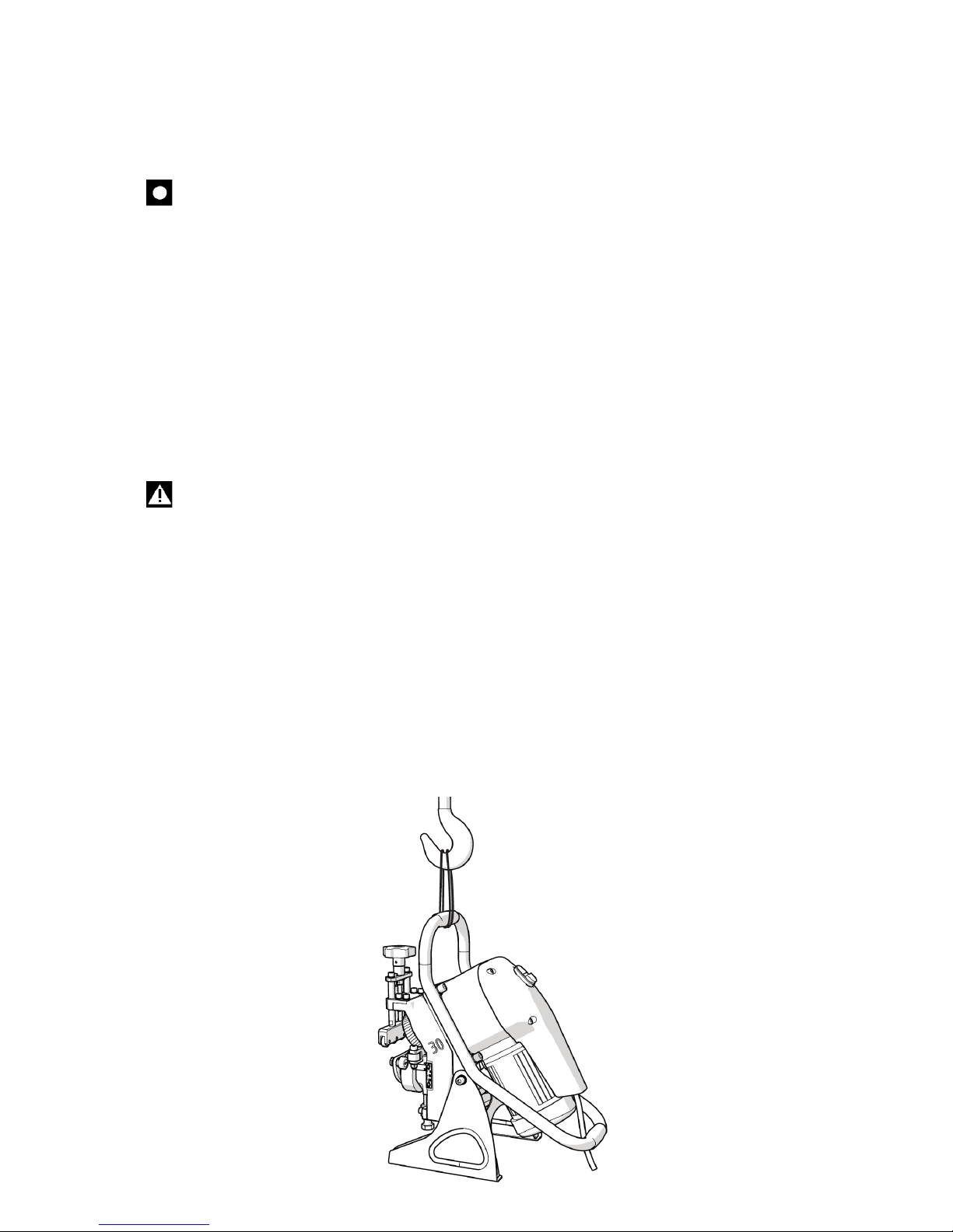
• If you are not able to bear the machine, lift it using suitable handling equipment and
strap for lifting of loads. The strap must be placed on the upper handle. It is shown in
fig. 4.1.1.
Fig. 4.1.1
12
4.2 Setting Up and Connecting
Important:
The activities described in this section must be performed by qualified personnel only.
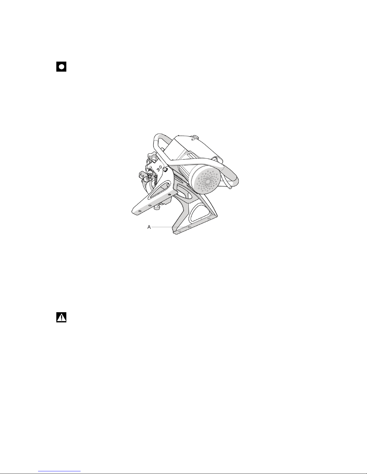
If the machine is used for machining of small workpieces, it must be fitted on a flat surface
(e.g. a workbench) using the opening in the bottom part of the stand (position A, fig. 4.2.1.).
Fig. 4.2.1.
If the machine is used for machining of large workpieces, it must be placed on the actual
workpiece and it must travel along the workpiece by itself during the work. The workers must
put the machine on the material and at the end of the process, they must take it off again. It is
advisable that the machine is suspended on the crane using a strap, as shown in fig. 4.1.1, at
least during approaching the material and at the end, when the material leaves the workpiece.
Caution:
If the machine is not adjusted correctly, the tool will not be sharp enough or the
machine will not be in a good condition. If inappropriate material to be machined is
selected, fall of the machine off the workpiece may occur.
While performing electrical connection, proceed as follows:
• check frequency and voltage values on the engine rating plate,
• attach the end of the cable to the mains using a plug according to your local electric
distribution system.

13
4.3 Inspections before Commissioning
Important:
Never start UZ 12 Ultralight without performing inspections described in this section.
Prior to starting the machine, make sure that the machine is operational within the following
inspections and checks in order to achieve the highest possible efficiency and compliance
with safety regulations:
• make sure no bolts or other parts are loose,
• make sure that all electrical connections have been made correctly and that the
electrical cable is held in its place by the cable bushing.
To start the machine, proceed as follows:
• Connect the machine to the mains
• Start the motor using the green button (position A, fig. 2.4.1). The cutter must
rotate in a clockwise direction.
If not, adjust wiring of the phase in the plug.
To stop the machine, use the red button placed next to the power button (position B, fig.
2.4.1).
4.4 Discard and Disposal Considerations
When disposing of the machine UZ12 Ultralight, keep in mind that materials it is made from
are not safe and that they include mainly the following items:
• painted or metal-coated steel and ALU alloys
• stainless steel, series 300/400
• plastic materials of various nature
• gear oil
• electric motor
• electric cabling and appropriate sheathing
• electrical monitoring and exciting devices.
Follow these steps:
• follow the applicable laws in force in your country relating to occupational safety,
• disconnect the machine from the power supply,
• dismantle the machine and sort the components into groups according to their
chemical properties,
• scrap machine parts in accordance with the applicable laws in force in your country,
• during dismantling stages, strictly adhere to applicable regulations for occupational
safety.

14
5.0 USE
5.1. Intended Use
The machine for bevel chamfering, model UZ 12 Ultralight was designed, manufactured and
sold for chamfering of metal semi-finished products and rolled profiles of the following types:
steel and stainless steel up to the strength Rm = 70 kg/mm2, brass, copper and aluminium.
Maximal bevel dimensions and thickness of the material subject to machining are detailed in
chapter 3, section 3.2, “Technical Specifications”.
Applications other that the above-mentioned intended ones are considered inappropriate. To
be specific, it is forbidden to:
• process products differing from those, for which the machine has been manufactured
and sold,
• modify the operation of the machine,
• replace parts with other that genuine components,
• modify electrical connections, thus eluding internal safety regulations,
• remove or modify safety guards,
• use the machine in places with aggressive atmospheres.
Caution:
It is strictly forbidden to perform bevel chamfering with materials other than those
mentioned above as their processing might expose the operator and the machine to risk.
Prior to any modifications, contact N.KO to issue the respective authorization. Otherwise
N.KO will not be held liable.
5.2 Description of Control Elements
• Green button (position A, fig. 2.4.1) - pressing the button starts the engine.
BEWARE of the sense of machine rotation. The working direction is clockwise
only.
• Red button - Emergency stop button (position B, fig. 2.4.1) - pressing this button
disconnects the power source.
5.3 Adjusting the Machine
Caution:
While adjusting the machine, use working gloves and other personal protective
equipment. Operations must be performed with the still machine and after the machine
has been disconnected from the power source.
Prior to start of any works, it is necessary to perform some adjustments.

15
Change to Bevel Angle
The machine UZ12 Ultralight as a standard comes with two or full set kits determining the
bevel angle
order no. 1922 - UZ12 + KIT 30° + 45°
order no. 1918 - UZ12 + KIT 22,5° + 30° + 37,5° + 45° + 50° + pipe bevelling tool
Other kits for angles of 37.5°/ 22.5°/ 50° can be purchased as optional accessories
order No. 1926 - KIT 22.5°
order No. 1923 - KIT 30 °
order No. 1925 - KIT 37.5°
order No. 1924 - KIT 45°
order No. 1929 - KIT 50°
Should you require a special angle, contact your vendor.
To change the bevel angle, proceed as follows:
• Loosen the bolts of the upper support console (position A, fig. 5.3.1) and dismantle the
entire assembly of the upper support.
• Loosen the central bolt (position B, fig. 5.3.1) of the lower support and dismantle the
entire support.
• Loosen the bolts of the console of the elevating screw (position C, fig. 5.3.1) and
dismantle the entire assembly of the elevating screw.
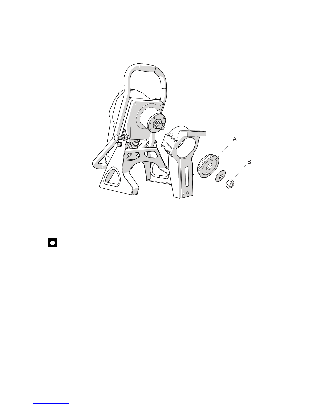
• Loosen the main nut of the cutter (position B, fig. 5.3.2) and dismantle the cutter
(position A, fig. 5.3.2).
• Now, it is the time to dismantle the kit. Loosen two Allen head bolts (position E, fig.
5.3.1).
• Using the distance bolt (position D, fig. 5.3.1) loosen the kit on the neck of the
machine and remove the kit (refer to fig. 5.3.2).
• Select the suitable kit according to the desired bevel angle and reassemble the machine
in the same way.
Fig. 5.3.1
16
Fig. 5.3.2
Important:
Adjusting the elevation of the lower cylinders (the support) sets the C value = the dulling
height, refer to fig. 5.3.3.!!!
The C value, which can be read on the scale (position C, fig. 5.3.5) indicates the
difference between the bevel height (dimension A in fig. 5.3.3.) and the total thickness of
the material.
Therefore, you set the so-called dulling on the scale (dimension C, fig. 5.3.3.).
(This means that for setting of the bevel size 8x8x45º on the material with a thickness of
10 mm, you have to set the value 2 mm on the scale).
It is important to note that while adjusting the dulling height C, such a value, at which
the hypotenuse length of the resulting bevel (dimension P in fig. 5.3.4.) would exceed 12
mm (maximum output of the machine), must be avoided. This can be checked in the
table 5.3.6.

17
Proceed in the following way:
• Loosen the bolt of the central cylinder (position A, fig. 5.3.5) sufficiently.
• Loosen the counter nut on the elevating screw (position B, fig. 5.3.5).
• By turning the elevating bolt (position D, fig. 5.3.5), set the required value of the
dulling height.
• The dulling value C can be read on the scale (position C, fig. 5.3.5).
• Having done the correct adjustments, lock the elevating bolt (position D, fig. 5.3.5)
using the counter nut (position B, fig. 5.3.5).
• Re-tighten the bolt of the centre cylinder (position A, fig. 5.3.5).
• Finally make sure that the main centre cylinder is free and can rotate. Otherwise it is
necessary to clean the room behind the centre cylinder.
fig. 5.3.3
fig. 5.3.4
Table 5.3.6
On the dulling scale C (position C, fig. 5.3.5)
it is FORBIDDEN to set lower value than indicated in the
right column of the table. There is a risk of machine
overloading.
Note: The indicated data apply to the steel strength up to 45
kg/mm².

18
Fig. 5.3.5.
It is forbidden to set the C value lower than indicated in the table.
Otherwise there is a risk of machine overloading.
All bevels, where the bevel width (hypotenuse P, fig. 5.3.4) exceeds 10 mm, must be
performed in two steps.
For the first draft, set the C value = required C + ½ A.
For the second draft, set the required C value.
Examples of Setting:
Example No. 1:
Can we create a bevel of 10x10x45
°
with a 12mm-thick material?
In order to perform the correct adjustment, we have to set the dulling C, i.e. the
difference between the height of the required bevel and the thickness of the material, on
the scale. This means: 12-10=2.
Therefore, 2 mm should be on the scale. To check whether the machine will not be
overloaded, use the table (fig. 5.3.6).
It can be read from the table that the minimum possible value on the scale can be 3.5
mm. This means that this bevel cannot be created, because 2 mm is less than 3.5 mm.
With this setting, the total hypotenuse of the bevel (dimension P in fig. 5.3.4) exceeds the
permitted 12 mm. Therefore, there is a risk of machine destruction.

19
Example No. 2.
Is it possible to make a bevel of 8x8x45
°
with 12mm-thick material?
To perform the correct adjustment, it is necessary to set the difference between the
height of the required bevel and the material thickness on the scale. This means: 12-8=4.
The scale should thus show 4 mm. To check whether the machine will not be overloaded,
use the table (fig. 5.3.6).
It can be read from the information that the scale can show the value of min. 3.5mm.
This means that this bevel can be made because 4 mm is more than 3.5 mm and with this
settings, the total bevel hypotenuse (dimension P in fig. 5.3.4) does not exceed the
permitted 12 mm.
But since the P hypotenuse exceeds 10 mm, it is advisable to make the planned bevel in
two steps. Step no. 1. C=8mm. Step no. 2. C=4mm.
Example no. 3:
Can we make the bevel of 6x6x45
°
with the 8mm-thick material?
For the correct adjustment, we have to set the difference between the required bevel
height and the material thickness on the scale (position C, fig. 5.3.5), i.e 8-6=2.
Therefore, 2 mm should be on the scale. To check if the machine is not overloaded, use
the table in fig. 5.3.6.
It can be read from the table, that the dulling for materials whose thickness does not
exceed 8 mm can be set without any limitations. This means that the bevel can be
created despite of the fact that we have set 0 mm on the scale and the sheet will be sharp
bevelled, the total bevel hypotenuse (dimension P in fig. 5.3.4), because the bevel does
not exceed the permitted 12 mm.
Adjustment of Workpiece Holder Cylinders
To ensure the correct operation of the machine, the workpiece holder cylinders (position G,
fig. 5.3.5) must exercise light pressure on the workpiece. Their adjustment shall be done as
follows:
• Turn the hand wheel in the upper part of the workpiece holder (position F, fig. 5.3.5)
which adjusts the height of holder cylinders.
• Make adjustment so that the cylinders exercise light pressure on the workpiece. Make
sure that the position is correct; read the value of the bevel height (dimension A in fig.
5.3.3) on the respective scale (position E, fig. 5.3.5).
5.4. Bevelling
Important:
Activities described in this section must be performed only after adjustments referred to
in the preceding sections.
To ensure correct operation of the machine, make sure the adjustments have been made
correctly. No indicated situation must occur: the workpiece subject to machining must be
placed relative to the lower cylinders and holder cylinder as described in situations 1 and 4 in
fig. 5.4.1.

20
Fig. 5.4.1
If the machine is used for machining of small workpieces, it must be fixed on a flat surface
(e.g. a workbench) using the opening in the bottom part of the stand (Position A, fig. 4.2.1).
The workpiece moves automatically during machining (fig. 5.4.2).
After adjustments and start of the machine, press the workpiece into all stops in the left and
right directions, so that it is caught by the cutting machine. When the workpiece leaves the
machine, protect it from fall on the ground, holding it with both your hands and pressing it
towards the rear part of the machine in order to prevent its forward twisting.
Important:
Beware of the sense of machine rotation. The working direction is clockwise only.
Fig. 5.4.2
Table of contents
Other N.KO Power Tools manuals


