V8Gen.VFordMustangupto2009
N2MBWOTBoxInstallationInstructions
NOTE:IfyouhaveaCDI(capacitivedischargeignitionsystem)pleasecontactusat
[email protected]foradditionalinstructions.DamagetoyourWOTBoxcanoccurifthe installationisnotcompletedcorrectly!Allstockignitionsareinductive,notcapacitive;ifyou
haven’tinstalledacapacitiveignitionsystemonyourvehicle,itdoesn’thaveone.
WARNING:Spark‐basedrev‐limiterscandamagecatalyticconverters.Ifyouhavecatalytic
convertersonyourcar,N2MBacceptsnoresponsibilityfordamagecausedbytheWOTBox.
Thisbeingsaid,manysuccessfulinstallshavebeenmadeonCatalytic‐Converterequipped
vehicles.Damageusuallyisonlycausedbyusingthelaunch‐controlfeatureformorethana
fewseconds,butonceagain,USEATYOUROWNRISKIFYOUHAVECATALYTICCONVERTERS!
Pleasevisitourwebsiteathttp://www.n2mb.comforthelatestversionoftheWOTBox
softwareandinstallationinstructions.
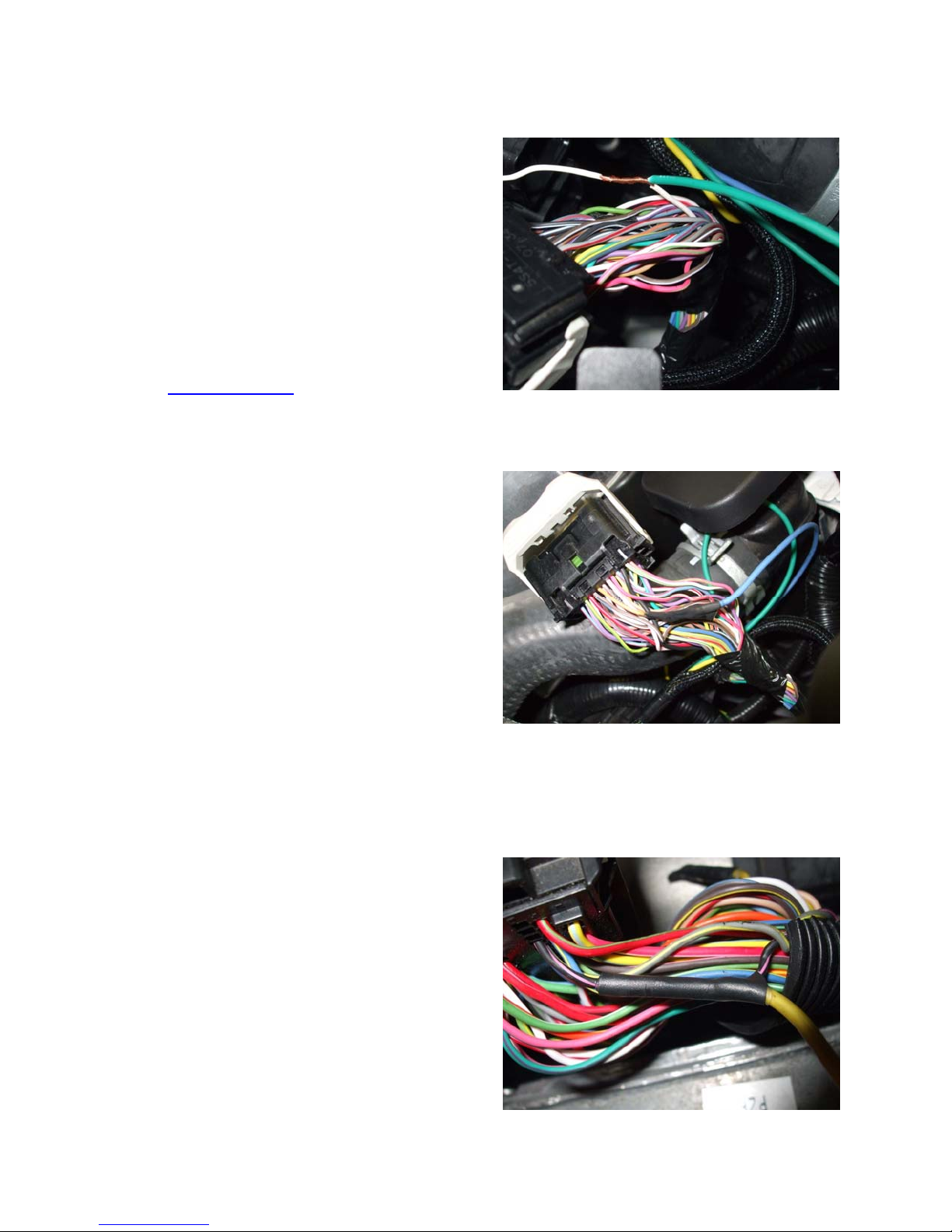
Solderalljoints.TheN2MBrecommendedsolderingmethodisavailableat
http://www.n2mb.com.Useamultimetertoverifyallwiresbeforetheyarecutortapped
into.Thecolorsofwiresfrommodelyeartomodelyearmaydiffer,andmaybedifferenton
yourcarfromthosedescribedintheseinstructions.Wherediscrepanciesareknown,they
aredescribed,buttheremaybemorediscrepanciesthanthoselisted.Thebestwaytoknow
thatyouhavetherightwireistochecktheconnectivitytotheECUand/orsensoratthepins
described.
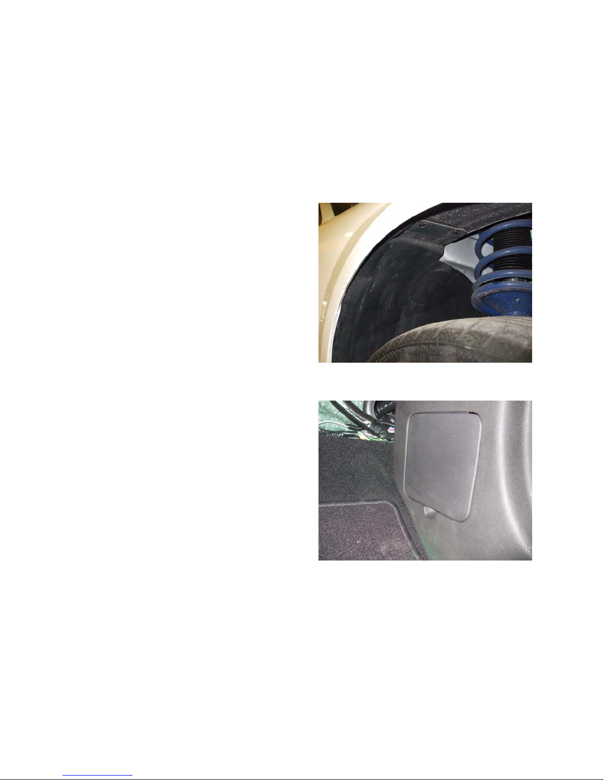
Intheseinstructions,picturesincludeotheraftermarketalterationsinadditiontotheWOT
Box.N2MBisnotaffiliatedwiththesedevices.Inaddition,ifyouseesomethingthatisn’tin
yourvehicle,don’tworry.
Routewiresinthemannerthatyouwantthemtoliepermanentlybeforeconnectingthem.
Cutwirestolengthbeforesoldering;avoidcoilingwiresofexcessivelengthastheycancause
noiseinthecircuit,alteringtheoperationoftheWOTBox.Spendingsomeextratimehere
willenhancetheaestheticsoftheinstall.Ziptiesareincludedtosecurethewiresawayfrom
heat,movingparts,sharpedges,oranythingelsethatcandamagethewires.